Motorola APX 1000 User Manual
Hide thumbs
Also See for APX 1000:
- User manual (166 pages) ,
- Manual (48 pages) ,
- User manual (136 pages)

Related Manuals for Motorola APX 1000


Summary of Contents for Motorola APX 1000
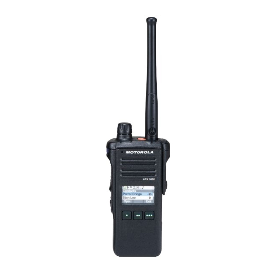
- Page 1 APX TWO-WAY RADIOS MODEL 3 APX 1000 USER GUIDE NOVEMBER 2020 *MN000255A01* MN000255A01-BN © 2020 Motorola Solutions, Inc. All rights reserved...
-
Page 2: Table Of Contents
MN000255A01-BN Contents Contents List of Tables....................... 9 Software Version.......................10 Chapter 1: Read Me First..................11 1.1 Notations Used in This Manual....................11 1.2 Radio Care..........................11 1.2.1 Cleaning Your Radio....................12 1.2.2 Cleaning the External Surface of the Radio.............13 1.2.3 Radio Service and Repair..................13 1.3 Battery Recycling and Disposal..................... - Page 3 MN000255A01-BN Contents 4.1.2 Accessing the Battery Info screen................26 4.1.3 HAZLOC Battery Type Detection................27 4.2 LED Indications........................27 4.3 Status Icons........................... 28 4.4 TMS Status Icons........................30 4.5 Call Type Icons........................30 4.6 Top Lightbar Indicator......................31 4.7 Intelligent Lighting Indicators....................31 4.8 Alert Tones ...........................
- Page 4 MN000255A01-BN Contents 6.1.4 Making a Priority Dispatch Calls................46 6.1.5 Dynamic Regrouping (Trunking Only)..............46 6.1.5.1 Classification of Regrouped Radios............46 6.1.5.2 Requesting a Reprogram (Trunking Only)..........47 6.1.6 Dynamic Zone Programming................... 47 6.1.6.1 Entering the Dynamic Zone to Select a Dynamic Channel......47 6.1.6.2 Saving a Channel in the Dynamic Zone from List Selection......
- Page 5 MN000255A01-BN Contents 6.6.2.1 Saving and Playback Calls.................60 6.7 In-Call User Alert........................61 6.8 Quick Call II .......................... 62 6.8.1 Initiating a Quick Call II Transmission..............62 6.9 Emergency Operation......................62 6.9.1 Special Considerations for Emergency Operation........... 63 6.9.2 Emergency Keep-Alive.................... 63 6.9.3 Exiting Emergency Operation.................. 63 6.9.4 Exiting Emergency as Supervisor (Trunking Only)..........
- Page 6 MN000255A01-BN Contents 6.13 ASTRO 25 Advanced Messaging Solution................77 6.13.1 Two-Factor Authentication..................78 6.13.1.1 Logging in using the Two-Factor Authentication........78 6.13.1.2 Logging out of Two-Factor Authentication..........79 6.13.2 Sending a Query....................79 6.13.3 Receiving a Query....................80 6.14 Radio Lock...........................81 6.14.1 Enabling or Disabling Radio Lock (Secure Radios Only)........81 6.14.2 Changing the Radio Lock Password..............81 6.14.3 Changing the Tactical Inhibit Password..............82...
- Page 7 MN000255A01-BN Contents 6.19 ASTRO 25 (P25) Programming Over Project 25 (POP25)..........93 6.19.1 Responding to the Notification of Upgrade............93 6.20 Voice Announcement ......................94 6.21 Utilities..........................94 6.21.1 Selecting the Power Level..................94 6.21.2 Selecting a Radio Profile..................95 6.21.3 Enabling and Disabling the Radio Alias..............96 6.21.4 Selecting the Audio Speaker..................96 6.21.5 Controlling the Display Backlight................
- Page 8 Declaration of Compliance for the Use of Distress and Safety Frequencies......117 Technical Parameters for Interfacing External Data Sources............117 Limited Warranty.....................118 MOTOROLA SOLUTIONS COMMUNICATION PRODUCTS........... 118 I. WHAT THIS WARRANTY COVERS AND FOR HOW LONG:..........118 II. GENERAL PROVISIONS:..................... 119 III.
-
Page 9: List Of Tables
MN000255A01-BN List of Tables List of Tables Table 1: Text Entry Modes........................21 Table 2: Keypad Characters........................21 Table 3: LED Indications........................27 Table 4: TMS Status Icons........................30 Table 5: Call Type Icons.........................30 Table 6: Emergency Operation Scenarios....................63 Table 7: Parameter Editing Keys......................107 Table 8: VHF Marine Channel List....................... -
Page 10: Software Version
MN000255A01-BN Software Version Software Version All the features described in the following sections are supported by the software version R21.60.00 or later. Accessing the Radio Information on page 102 to determine the software version of your radio. Contact your system administrator for more details of all the supported features. -
Page 11: Chapter 1: Read Me First
MN000255A01-BN Read Me First Chapter 1 Read Me First This User Guide covers the basic operation of the radio. However, your dealer or system administrator may have customized your radio for your specific needs. Check with your dealer or system administrator for more information. -
Page 12: Cleaning Your Radio
MN000255A01-BN Chapter 1: Read Me First CAUTION: Use the radio according to the following recommendations and warnings. • Your radio casing has a vent port for pressure equalization in the radio. Never poke this vent with objects such as needles, tweezers, or screwdrivers. •... -
Page 13: Cleaning The External Surface Of The Radio
Radio Service and Repair Proper repair and maintenance procedures ensure efficient operation and long life of this radio. A Motorola Solutions maintenance agreement provides expert service to keep the radio and all other communication equipment in perfect operating condition. A nationwide service organization is provided by Motorola Solutions to support maintenance services. -
Page 14: Astro 25 Enhanced Data
1.4.6 P25 Digital Vehicular Repeater System Motorola Solutions offers an MSI Certified APX compatible, third party, P25 Digital Vehicular Repeater System (DVRS) that provides low-cost portable radio coverage in areas where only mobile radio coverage is available and portable radio coverage is either intermittent or non-existent. -
Page 15: What Your Dealer/System Administrator Can Tell You
MN000255A01-BN Chapter 1: Read Me First • Mixed Vote Scan. • Standard Conventional Scan. • Priority Operation. Up to 30 different talkgroups can be supported using conventional channels. A maximum of four talkgroups can be supported when Vote Scan channels are being used. Smart PTT is supported with this enhancement as Smart PTT prevents you from transmitting while other users are on the channel. -
Page 16: Chapter 2: Preparing Your Radio For Use
NOTICE: When charging a battery attached to a radio, the radio must be turned off. Procedure: To charge the battery, place the battery (with or without the radio) in a Motorola Solutions- approved charger. The LED on the charger indicates the charging progress, see the Charger User Guide. -
Page 17: Attaching The Antenna
MN000255A01-BN Chapter 2: Preparing Your Radio for Use Attaching the Antenna Prerequisites: Ensure the radio is turned off before attaching the antenna. Procedure: 1 Set the antenna in the receptacle. 2 Turn the antenna clockwise to attach to the radio. 3 To remove the antenna, turn the antenna counterclockwise. -
Page 18: Adjusting The Volume
MN000255A01-BN Chapter 2: Preparing Your Radio for Use • If the power-up test is unsuccessful, you see Error XX/YY (XX/YY is an alphanumeric code). NOTICE: If the radio fails to power-up after repeating a few times, record the Error XX/YY code and contact your dealer. -
Page 19: Chapter 3: Radio Controls
MN000255A01-BN Radio Controls Chapter 3 Radio Controls This chapter explains the buttons and functions to control the radio. Radio Parts and Controls Top (Orange) Button This button is usually programmed as the Emergency button. Top Lightbar Microphone These radio controls/buttons are programmable. - Page 20 MN000255A01-BN Chapter 3: Radio Controls Top Side (Select) Button Use this programmable button to access a preprogrammed function or enable or dis- able a feature. Push-to-Talk (PTT) Button Press and hold to talk in simplex calls or to initiate a group call, release it to listen. Side Button 1 Use this programmable button to access a preprogrammed function or enable or dis- able a feature.
-
Page 21: Keypad
MN000255A01-BN Chapter 3: Radio Controls Keypad Use the keypad to enter alphanumeric text on your radio. Your radio uses icons to indicate the selected text entry mode. Refer to the following table for the supported modes. Table 1: Text Entry Modes Icon Description Text entry is in hexadecimal mode. -
Page 22: Programmable Features
MN000255A01-BN Chapter 3: Radio Controls Mode Output 5 key Numeric Uppercase J K L Lowercase j k l 6 key Numeric Uppercase M N O Lowercase m n o 7 key Numeric Uppercase P Q R S Lowercase p q r s 8 key Numeric Uppercase... - Page 23 MN000255A01-BN Chapter 3: Radio Controls NOTICE: • If the Dynamic ID menu key is not pre-programmed in the radio, use dongle to display the menu key. Press the menu key and enter the password to view or edit the ASTRO Individual ID and/or MDC Primary ID of the radio.
-
Page 24: Assignable Settings Or Utility Functions
MN000255A01-BN Chapter 3: Radio Controls Recent Calls Allows you to view the recent call history of your radio. Repeater Access Button (RAB) (Conventional Only) Allows you to manually send a repeater access codeword. Reprogram Request (Trunking Only) Notifies the dispatcher that a new dynamic regrouping assignment is needed. Request-To-Talk (Conventional Only) Notifies the dispatcher that you want to send a voice call. - Page 25 MN000255A01-BN Chapter 3: Radio Controls Voice Mute Toggles the voice transmission between mute and unmute. Volume Set Tone Sets the volume set tone.
-
Page 26: Chapter 4: Status Indicators
MN000255A01-BN Chapter 4: Status Indicators Chapter 4 Status Indicators This section explains the status indicators of the radio. Battery Charge Status Your radio indicates the battery charge status through LED, sounds, and the fuel gauge icon on the display. You can also check the battery charge status by using the menu entry. If you press the PTT button when your battery is low, the LED blinks red and you hear a short, high- pitched tone. -
Page 27: Hazloc Battery Type Detection
MN000255A01-BN Chapter 4: Status Indicators Remaining Capacity Remaining power of the battery in mAh. Estimated Charges Number of charges cycles the battery has gone through. 3 To return to the Home screen, press the Menu Select button directly below Exit. 4.1.3 HAZLOC Battery Type Detection This feature alerts the user when there is a HAZLOC certification mismatch between the radio and the... -
Page 28: Status Icons
MN000255A01-BN Chapter 4: Status Indicators Indication Status Rapid blinking green Radio is on a Priority-One channel while in the Scan List Programming mode. Status Icons The 240 x 320 pixel front liquid crystal display (LCD) of your radio shows radio status, text entries, and menu entries. - Page 29 MN000255A01-BN Chapter 4: Status Indicators Icon Description Radio is scanning a scan list. Blinking dot Radio detects activity on channel designated as Priority-One. Steady dot Radio detects activity on channel designated as Priority-Two. The vote scan feature is enabled. Secure operation. Clear operation.
-
Page 30: Tms Status Icons
MN000255A01-BN Chapter 4: Status Indicators TMS Status Icons The following icons appear on the radio display when you send and receive text messages. Table 4: TMS Status Icons Icon Description The Inbox is full. The text message is sent. The text message cannot be sent. The selected text message in the Inbox is not read. -
Page 31: Top Lightbar Indicator
MN000255A01-BN Chapter 4: Status Indicators Icon Description Mobile number added to a Call List. Landline phone number. Landline phone number added to a Call List. Incoming call or data. Outgoing call or data. Incoming emergency call. Top Lightbar Indicator The Top Lightbar indicates the secondary function of MFK and also the status of Intelligent Lighting. -
Page 32: Alert Tones
MN000255A01-BN Chapter 4: Status Indicators Backlight and Notification When Bar Color The radio is out of range. The radio enters Failsoft mode. The radio is unable to establish a full connection with the system. The radio is unable to authenticate or register with the system. - Page 33 MN000255A01-BN Chapter 4: Status Indicators You Hear Tone Name Heard Out of Range (When PTT button is pressed) the radio is out of range of the system. Invalid Mode When radio is on an unpreprogrammed channel. A Group of Busy When system is busy.
-
Page 34: Phone Call Displays And Alerts
MN000255A01-BN Chapter 4: Status Indicators You Hear Tone Name Heard Unique, Priority Status When a priority message is received. High-Pitch- ed Chirp Unique MFK Enters Secon- When MFK is toggled to secondary feature. Low-High dary Feature Tone Unique MFK Exits Secondary When MFK is toggled to exit secondary feature and re- High-Low Feature... - Page 35 MN000255A01-BN Chapter 4: Status Indicators The backlight on top lightbar indicator turns off and if connected to DRSM, the DRSM backlight changes to white for the following scenarios: • When changing to or powering up on invalid channels such as unprogrammed channels, receiver frequency error channel and blank channels For hard key zeroize, key loading, and scan list programming, the backlight follows the home channel backlight color.
-
Page 36: Chapter 5: General Radio Operation
MN000255A01-BN Chapter 5: General Radio Operation Chapter 5 General Radio Operation This chapter explains the general operations of your radio. Selecting a Zone When and where to use: A zone is a group of channels. Do one of the following to select a radio channel. -
Page 37: Selecting A Channel By Using Channel Search Button
MN000255A01-BN Chapter 5: General Radio Operation b. Press the Menu Select button directly below Chan . to the required channel or use the keypad to enter the channel number. If the channel number entered is unprogrammed, the display shows Invalid entry. Repeat this step. -
Page 38: Saving A Zone And A Channel To A Softkey
MN000255A01-BN Chapter 5: General Radio Operation 5.4.1 Saving a Zone and a Channel to a Softkey When and where to use: Five softkeys are available for you to save the frequently used zone and channel. Procedure: 1 Toggle from your current zone and channel to the required zone and channel. or to MS1, MS2 ... -
Page 39: Receiving And Responding To A Private Call (Trunking Only)
MN000255A01-BN Chapter 5: General Radio Operation • For Trunking system, the display shows the caller alias or ID. Procedure: 1 Hold the radio vertically 1 to 2 inches (2.5 to 5.0 cm) from your mouth. 2 Press the PTT button to respond to the call. The LED lights up solid red. -
Page 40: Making A Talkgroup Call
MN000255A01-BN Chapter 5: General Radio Operation • MFK preprogrammed with Channel Change or Zone Change function. • A preprogrammed button. • The Contacts list (see Viewing Details of a Contact on page 54). 5.6.1 Making a Talkgroup Call Procedure: 1 Turn the MFK to select the channel with the desired talkgroup. 2 Hold the radio vertically 1 to 2 inches (2.5 to 5.0 cm) from your mouth. -
Page 41: Making An Enhanced Private Call (Trunking Only)
MN000255A01-BN Chapter 5: General Radio Operation 5.6.3 Making an Enhanced Private Call (Trunking Only) Prerequisites: Your radio must be preprogrammed to allow you to use this feature. When and where to use: This feature allows you to send an individual Call Alert Page if there is no answer from the target radio. -
Page 42: Switching Between Repeater Or Direct Operation Button
MN000255A01-BN Chapter 5: General Radio Operation 5 When your call is answered, press and hold the PTT button to talk. Release the PTT button to listen. 6 Press to return to the Home screen. Phone Call Displays and Alerts on page 34 for more information if your call is not answered. -
Page 43: Monitoring Conventional Mode
MN000255A01-BN Chapter 5: General Radio Operation d. Press and hold the PTT button to transmit. The LED lights up solid red. e. Release the PTT button to receive (listen). 5.8.2 Monitoring Conventional Mode This feature allows you to monitor channel traffic on conventional channels by defeating the coded squelch. -
Page 44: Chapter 6: Advanced Features
MN000255A01-BN Chapter 6: Advanced Features Chapter 6 Advanced Features This chapter explains the operations of the features available in your radio. Advanced Call Features This chapter explains the operations of the call features available in your radio. 6.1.1 Selective Call (ASTRO Conventional Only) A Selective Call is a call from an individual radio to another individual radio with privacy. -
Page 45: Talkgroup Call Feature (Conventional Only)
MN000255A01-BN Chapter 6: Advanced Features The display shows the ID of the target radio. 5 Release the PTT button to listen. 6 Press to return to the Home screen. 6.1.2 Talkgroup Call Feature (Conventional Only) This feature allows you to define a group of conventional system users so that they can share the use of a conventional channel. -
Page 46: Making A Priority Dispatch Calls
MN000255A01-BN Chapter 6: Advanced Features If no acknowledgment is received, you hear a low-pitched tone and the display shows No acknowledge. 4 Press to return to the Home screen. No traffic is heard on trunked channels while Status Call is selected. If the radio detects no Status Call activity for six seconds, an alert tone sounds until you press or the PTT button. -
Page 47: Requesting A Reprogram (Trunking Only)
MN000255A01-BN Chapter 6: Advanced Features Select Disabled Select-disabled radios cannot change channels while dynamically regrouped. The radio is forced to remain on the dynamic-regrouping channel. The Scan and Private Call features are unavailable when your radio is Select Disabled. 6.1.5.2 Requesting a Reprogram (Trunking Only) This feature allows you to notify the dispatcher when you want a new dynamic regrouping assignment. -
Page 48: Saving A Channel In The Dynamic Zone From List Selection
MN000255A01-BN Chapter 6: Advanced Features If you have selected Exit without selecting any Dynamic Zone Channels list, the display returns to Home screen without any changes. 6.1.6.2 Saving a Channel in the Dynamic Zone from List Selection Prerequisites: To perform this operation, the radio must be in the Dynamic Zone. Procedure: or to ZnPr. -
Page 49: Deleting A Channel In The Dynamic Zone
MN000255A01-BN Chapter 6: Advanced Features 6 Press to return to the Home screen. 6.1.6.4 Deleting a Channel in the Dynamic Zone Prerequisites: To perform this operation, the radio must be in the Dynamic Zone. Procedure: or to ZnPr then press the Menu Select button directly below ZnPr to enter Program Zone screen. -
Page 50: Contacts
MN000255A01-BN Chapter 6: Advanced Features • If you select a single source zone, press the Menu Select button directly below Sel to select the target zones for cloning. • If you select multi-source zones, the radio displays Confirm target and shows the automatically selected target zones and source zones mapping. -
Page 51: Making A Private Call From Contacts
MN000255A01-BN Chapter 6: Advanced Features 6.2.1 Making a Private Call from Contacts Prerequisites: Your radio must be preprogrammed to allow you to use this feature. Procedure: or to Cnts and press the Menu Select button directly below Cnts. The entries are alphabetically sorted. to the required subscriber alias. -
Page 52: Deleting A Contact Entry
MN000255A01-BN Chapter 6: Advanced Features 7 Use the keypad to enter the number and press the Menu Select button directly below Ok once you have entered the number. To cancel this operation, press the Menu Select button directly below Cncl to return to the previous screen. -
Page 53: Removing A Contact From A Call List
MN000255A01-BN Chapter 6: Advanced Features 6.2.5 Removing a Contact from a Call List Procedure: or to Cnts and press the Menu Select button directly below Cnts . The entries are alphabetically sorted. to the entry you want to delete and press the Menu Select button directly below Optn . to Rm frm CallLst and press the Menu Select button directly below Sel . -
Page 54: Editing A Call Type
MN000255A01-BN Chapter 6: Advanced Features to the entry you want to edit and press the Menu Select button directly below Optn . to Edit and press the Menu Select button directly below Sel . to the entry ID you wish to change and press the Menu Select button directly below Edit . -
Page 55: Intelligent Priority Scan
MN000255A01-BN Chapter 6: Advanced Features • Talkgroup Scan List • Trunking Priority Monitor Scan List Refer to a qualified radio technician for the maximum number of Scan Lists to be preprogrammed in your radio. 6.3.1 Intelligent Priority Scan Intelligent Priority Scan feature allows you to add or delete conventional channels and trunking talkgroups from multiple system into the priority scan lists. -
Page 56: Changing The Scan List Status
MN000255A01-BN Chapter 6: Advanced Features • Press to exit scan list programming and return to the Home screen. Viewing and Changing the Priority Status on page 56 for more information on how to add and/or change the priority of the currently displayed channel in the scan list. 6.3.4 Changing the Scan List Status Procedure:... -
Page 57: Scan
MN000255A01-BN Chapter 6: Advanced Features Scan This feature allows you to monitor traffic on different channels by scanning a preprogrammed list of channels. Scanning is halted if you initiate a call and resumes when the call has ended. 6.4.1 Turning Scan On or Off Procedure: Perform one of the following actions: •... -
Page 58: Restoring A Nuisance Channel
MN000255A01-BN Chapter 6: Advanced Features 6.4.4 Restoring a Nuisance Channel Procedure: To restore the deleted nuisance channel, perform one of the following actions: • Stop and restart a scan. • Mode change to another channel and back to the original channel. •... -
Page 59: Recent Calls
MN000255A01-BN Chapter 6: Advanced Features d. Press the PTT button to send the page. The display shows Paging...<Number>. If the call alert page is sent successfully, you hear a tone and the display shows Ack received. The radio returns to the Home screen. If the call alert page is not acknowledged, you hear a low tone and the display shows No acknowledge. -
Page 60: Instant Recall
MN000255A01-BN Chapter 6: Advanced Features a. Press the preprogrammed Recent Calls button. to scroll through the list. c. To view the recent Emergency calls, press the Menu Select button directly below Emer. Press the Menu Select button directly below All to view back all recent calls. d. -
Page 61: In-Call User Alert
MN000255A01-BN Chapter 6: Advanced Features a. Press the Menu Select button directly below Rcnt. to Saved Convs and press the Menu Select button directly below Sel to view the recent conversations. to the required call and press the Menu Select button directly below Play. Radio playback the selected call and auto playback the saved calls in chronological order. -
Page 62: Quick Call Ii
MN000255A01-BN Chapter 6: Advanced Features Quick Call II This feature allows you to broadcast a series of distinct, recognizable tones before a voice transmission from the dispatcher or a radio. The broadcasting dispatcher or radio user can select this pre-programmed alert tone transmission to be sent to an individual talkgroup or over the entire system. -
Page 63: Special Considerations For Emergency Operation
MN000255A01-BN Chapter 6: Advanced Features Non-Tactical/Revert for Trunking System The radio reverts to the preprogrammed emergency talkgroup (trunking system) or channel (conventional system) to send an alarm and/or make an emergency call. Contact your system administrator for more information. 6.9.1 Special Considerations for Emergency Operation The following scenarios apply during Emergency operation: Table 6: Emergency Operation Scenarios... -
Page 64: Sending An Emergency Alarm
MN000255A01-BN Chapter 6: Advanced Features If… Then… If the emergency mode is ini- press and hold the Side Button 1 and press the Emer- tiated by other radios, gency button. If the emergency mode is ini- Perform one of the following actions: tiated by the Supervisor, •... -
Page 65: Sending An Emergency Call (Trunking Only)
MN000255A01-BN Chapter 6: Advanced Features 6.9.6 Sending an Emergency Call (Trunking Only) When and where to use: This feature gives your radio priority access to a talkgroup. Procedure: 1 Press the preprogrammed Emergency button. One of the following scenarios occurs: •... -
Page 66: Sending An Emergency Alarm And Call With Hot Mic
MN000255A01-BN Chapter 6: Advanced Features This feature gives your radio priority access on a channel for conventional system, and to a talkgroup for trunking system. Procedure: 1 Press the preprogrammed Emergency button. If successful, the display shows Emergency on the current zone and channel. You hear a short, medium-pitched tone and the LED blinks red momentarily. -
Page 67: Sending A Silent Emergency Alarm
MN000255A01-BN Chapter 6: Advanced Features Turning off the radio also cancels the emergency state. 6.9.10 Sending a Silent Emergency Alarm When and where to use: This feature allows you to send an Emergency Alarm to the system without triggering any audio or visual indicators. Procedure: 1 Press the preprogrammed Emergency button. -
Page 68: User Login Feature
MN000255A01-BN Chapter 6: Advanced Features a. Once the zone you want is displayed, turn the preprogrammed MFK to the desired mode. • Selecting or Changing the ARS mode using the radio menu: or to Chan . b. Press the Menu Select button directly below Chan . The display shows the current channel name. -
Page 69: Logging Out
MN000255A01-BN Chapter 6: Advanced Features • In ARS Server Mode, the display shows the User Login Indicator icon, the ID, and In progress, with Cncl . • In ARS Non-Server Mode, the display shows the User Login Indicator icon, the ID, and Logged in, with Logt and Exit. -
Page 70: Accessing The Messaging Features
MN000255A01-BN Chapter 6: Advanced Features • An edited quick text message. • A query (ASTRO 25 Advanced Messaging Solution). NOTICE: Query is only supported in the ASTRO 25 Advanced Messaging Solution. For more information, see ASTRO 25 Advanced Messaging Solution on page 77 Two-Factor Authentication on page 6.12.1... -
Page 71: Sending A Quick Text Message
MN000255A01-BN Chapter 6: Advanced Features The display shows the Send Message screen and Sending msg. If the message is sent, you hear a tone and the display shows Msg sent. If the message is not sent, you hear a low tone, the display shows Send failed and returns to the main TMS screen. -
Page 72: Priority Status And Request Reply Of A New Text Message
MN000255A01-BN Chapter 6: Advanced Features 9 Press the Menu Select button directly below Send or press the PTT button to send the message. The display shows the Send Message screen and Sending msg. If the message is sent, you hear a tone and the display shows Msg sent. If the message is not sent, you hear a low tone, the display shows Send failed and returns to the main TMS screen. -
Page 73: Appending A Request Reply To A Text Message
MN000255A01-BN Chapter 6: Advanced Features 6.12.4.3 Appending a Request Reply to a Text Message Prerequisites: Ensure that an outgoing message is composed to allow you to perform this procedure. Composing and Sending a New Text Message on page 70 for more information Procedure: 1 Press the Menu Select button directly below Optn . -
Page 74: Receiving A Text Message
MN000255A01-BN Chapter 6: Advanced Features to No Req Reply and press the Menu Select button directly below Sel to remove the reply status icon. The display shows the normal message icon on the label bar. 6.12.4.7 Receiving a Text Message When and where to use: NOTICE: When you receive a message that is flagged with the Request Reply icon, you must manually respond to the sender that you have received the message. -
Page 75: Replying To A Received Text Message
MN000255A01-BN Chapter 6: Advanced Features • Select Back to return to the previous screen. NOTICE: The icon at the top right corner of the screen indicates the status of the message. See Status Indicators on page 26 for more information. 6.12.4.9 Replying to a Received Text Message When and where to use:... -
Page 76: Sent Text Messages
MN000255A01-BN Chapter 6: Advanced Features to Drafts and press the Menu Select button below Sel . The display shows a list of drafts, with the latest text message drafted on top. to the required text message and press the Menu Select button below Sel to view the message. -
Page 77: Deleting A Text Message
ASTRO 25 Advanced Messaging Solution The ASTRO 25 Advanced Messaging Solution allows you to quickly send and receive messages and run database queries directly from your data-enabled Motorola Solutions two-way radios. Federal mandate requires Two-Factor Authentication when querying Federal and State databases. -
Page 78: Two-Factor Authentication
MN000255A01-BN Chapter 6: Advanced Features warrants. Query and Two-Factor Authentication has Criminal Justice Information Services (CJIS) security compliance for queries. 6.13.1 Two-Factor Authentication This feature allows you to log in and authenticate yourself with a username, unit ID, password, and passcode. -
Page 79: Logging Out Of Two-Factor Authentication
MN000255A01-BN Chapter 6: Advanced Features • Press and hold to scroll through the list of predefined Unit IDs at a fast scroll rate. Press the Menu Select button directly below Sel to select the predefined Unit ID. If the selected predefined Unit ID has more than the maximum allowed characters, or an invalid character in it, the display shows momentary Invalid UnitID. -
Page 80: Receiving A Query
MN000255A01-BN Chapter 6: Advanced Features You shall receive a service advertisement message to indicate the Query is available after you have successfully logged in the radio with a Two-Factor Authentication. NOTICE: The query server must be selected as the destination so that it can receive the query message and respond the query with text message. -
Page 81: Radio Lock
MN000255A01-BN Chapter 6: Advanced Features When you receive a query, you hear a unique, high-pitched chirp and the display shows the message icon flagged with “Priority”. The display shows momentary New msg. Procedure: To access the Inbox, press and hold the Data Feature button or the preprogrammed TMS Feature button or press the Menu Select button directly below TMS. -
Page 82: Changing The Tactical Inhibit Password
MN000255A01-BN Chapter 6: Advanced Features 5 Enter the old password. 6 Press the Menu Select button directly below Ok . 7 Enter the new password. 8 Press the Menu Select button directly below Ok . 9 Re-enter the new password. 10 Press the Menu Select button directly below Ok . -
Page 83: Global Positioning System/Global Navigation Satellite System
MN000255A01-BN Chapter 6: Advanced Features NOTICE: If the radio has Inter-system roaming capability, the system administrator is able to put the radio into a non-functional state when the missing radio roams to another system. The radio can only be uninhibited by receiving an uninhibited command from the system administrator. -
Page 84: Location Format
MN000255A01-BN Chapter 6: Advanced Features Programmable Waypoints Preprogrammed Waypoints • Last Known Location • Destination Only the alias is editable, not the coordinates. The Home and Destination coordinates are ed- itable. Coordinates can be deleted one at a time, or all Coordinates cannot be deleted. -
Page 85: Selecting Location Format
MN000255A01-BN Chapter 6: Advanced Features • Press the Menu Select button directly below Optn. to Turn On GPS and press the Menu Select button directly below Sel. The front display shows the MGRS or latitude/longitude location, time, and date of the last successful location fix. -
Page 86: Viewing A Saved Waypoint
MN000255A01-BN Chapter 6: Advanced Features • to Save as Dest. and press the Menu Select button directly below Sel and proceed to step A blinking cursor appears on the screen. 3 Use the keypad to edit the auto-generated waypoint, if required, or press the Menu Select button directly below Cncl to return to the Location main screen. -
Page 87: Editing The Coordinates Of A Waypoint
MN000255A01-BN Chapter 6: Advanced Features to Edit name and press the Menu Select button directly below Sel . A blinking cursor appears in the Edit Name screen. 5 Use the keypad to edit the alias. 6 Perform one of the following actions: •... -
Page 88: Deleting A Single Saved Waypoint
MN000255A01-BN Chapter 6: Advanced Features 7 Press the Menu Select button directly below Ok once complete setting up the new Home or Destination. One of the following scenarios occurs: • The display shows [Home] Updated and the radio returns to the Waypoints main screen. •... -
Page 89: Measuring The Distance And Bearing From A Saved Waypoint
MN000255A01-BN Chapter 6: Advanced Features 5 Press the Menu Select button directly below Yes to delete all waypoints or press the Menu Select button directly below No to return to the Waypoints main screen. The display shows All saved waypnts deleted. 6.16.13 Measuring the Distance and Bearing from a Saved Waypoint Prerequisites: Ensure your radio shows the current location on the screen. -
Page 90: Mission Critical Geofence (Astro 25 Trunking)
MN000255A01-BN Chapter 6: Advanced Features NOTICE: If the transmitting radio is stale at the location after a period, the receiving radio display shows the last known location. If the transmitting radio does not have GPS or the receiving radio could not decode the GPS signal of the received signal, the receiving radio display shows the location as unknown. -
Page 91: Mission Critical Geofence
MN000255A01-BN Chapter 6: Advanced Features The following procedure guides you to exit the text message received. Procedure: Press the Menu Select button below Exit or to return to Home screen. The other operations are the same as normal dynamic regroup command. When the radio exits the Geofence area, your radio reverts to original channel or newly assigned talkgroup. -
Page 92: Operating In Failsoft System
MN000255A01-BN Chapter 6: Advanced Features 6.18.1 Operating in Failsoft System When and where to use: The failsoft system ensures continuous radio communication during a trunked system failure. If a trunking system fails completely, the radio goes into failsoft operation and automatically switches to its failsoft channel. -
Page 93: Viewing The Current Site
MN000255A01-BN Chapter 6: Advanced Features • To unlock the site, press the Menu Select button directly below Unlk. The display shows Site unlocked. The radio saves the new site lock state and returns to the Home screen. 6.18.5 Viewing the Current Site Procedure: Perform one of the following actions: •... -
Page 94: Voice Announcement
MN000255A01-BN Chapter 6: Advanced Features • Press the Menu Select button below Rej to reject the request to upgrade. One of the following scenarios occurs: • If you choose to accept, the display shows Programming Dont power off to indicate the upgrade is about to begin. -
Page 95: Selecting A Radio Profile
MN000255A01-BN Chapter 6: Advanced Features Do one of the following to select the power level. You can use the options interchangeably depending on your preference and the programmed functions. Procedure: • Selecting the Power Level using the Transmit Power Level switch: a. -
Page 96: Enabling And Disabling The Radio Alias
MN000255A01-BN Chapter 6: Advanced Features 6.21.3 Enabling and Disabling the Radio Alias When and where to use: This feature allows you to display or hide the radio alias (name). Procedure: Press the Menu Select button directly below MyID. The display shows momentary Radio ID off, and the radio alias disappears from the Home screen or the display shows momentary Radio ID on, and the radio alias appears on the Home screen. -
Page 97: Controlling The Display Backlight
MN000255A01-BN Chapter 6: Advanced Features 6.21.5 Controlling the Display Backlight When and where to use: You can enable or disable the radio display backlight as needed, if poor light conditions make the display or keypad difficult to read. Depending on how your radio is preprogrammed, you can also maintain a minimum backlight level on the radio front display. -
Page 98: Turning Voice Mute On Or Off
MN000255A01-BN Chapter 6: Advanced Features 6.21.8 Turning Voice Mute On or Off This feature allows you to mute the voice transmission of the current zone and channel. When and where to use: Do one of the following to turn Voice Mute on or off. You can use the options interchangeably depending on your preference and the programmed functions. -
Page 99: Editing The Time And Date
MN000255A01-BN Chapter 6: Advanced Features 6.21.10.1 Editing the Time and Date Procedure: or to Clck. 2 Press the Menu Select button directly below Clck. The display shows the current setting of the radio. 3 Press the Menu Select button directly below Edit. The first item blinks. -
Page 100: Conventional Squelch Operation
MN000255A01-BN Chapter 6: Advanced Features 6.21.12 Conventional Squelch Operation This feature filters out unwanted calls with low signal strength or channels that have a higher than normal background noise. Analog Options Tone Private Line, Digital Private-Line, and carrier squelch is available (preprogrammed) per channel. Option Result Carrier squelch... -
Page 101: Digital Ptt Id Support
MN000255A01-BN Chapter 6: Advanced Features Procedure: Place the preprogrammed PL Defeat switch in the PL Defeat position. One of the following occurs: • The radio plays the active transmission on the channel. • If no activity is present, the radio is muted 6.21.14 Digital PTT ID Support This feature allows you to see the radio ID (number) of the radio from whom you are currently receiving... -
Page 102: Enabling Transmit Inhibition
MN000255A01-BN Chapter 6: Advanced Features 6.21.16.1 Enabling Transmit Inhibition Procedure: 1 Perform one of the following actions: • or to TxIn. Press the Menu Select button below TxIn. • Press the Transmit Inhibit programmable button. NOTICE: If the user has disabled TX Inhibit using the menu and then moves the switch to the position where TX Inhibit is enabled, the new value overwrites the menu value. -
Page 103: Viewing The Ip Information
MN000255A01-BN Chapter 6: Advanced Features • • Flash Code • Tuning Version • Option Board Type (optional) • Expansion Board Type (optional) • MFK Secondary Function • DSP Version • KG (Secure Algorithm) • Serial Number • Flash Size and Type •... -
Page 104: Viewing The Control Assignments
MN000255A01-BN Chapter 6: Advanced Features to IP Info and press the Menu Select button directly below Sel. The display shows the IP Info screen. 3 Perform one of the following actions: • to scroll through the various information. • Press the Menu Select button directly below Back to return to the previous screen. •... -
Page 105: Front Panel Programming
MN000255A01-BN Chapter 6: Advanced Features 4 Use the keypad to edit the text. 5 Perform one of the following actions: • Press the Menu Select button directly below Ok to save the new Soft ID and return to the previous screen. •... -
Page 106: Changing Password (Optional)
6.21.18.2 Changing Password (Optional) Prerequisites: Radios from the Motorola Solutions factory are provisioned with a blank password. In this case, press the OK softkey immediately at the Enter Old password: prompt to change the password, to access the protected channels. -
Page 107: Editing Parameters
MN000255A01-BN Chapter 6: Advanced Features • to select other channel parameters. • Press BACK to access a different channel and make any necessary programming changes. 8 Press BACK to return to Zone List Selector. 9 Press BACK to return to FPP main menu. 10 Press to return to the Home screen. - Page 108 MN000255A01-BN Chapter 6: Advanced Features Parameter Editing Keys Value Tx Deviation 5.0 kHz/4.0 kHz/2.5 kHz Power Level High/Low Hot Keypad ON/OFF Busy LED ON/OFF Low Batt ON/OFF MPL Enable Disabled/Rx /Tx/All Scan List None/Scan List 1, 2, 3,... Zone Name Use keypad to enter numbers and alphabet characters.
-
Page 109: Chapter 7: Accessories
MN000255A01-BN Accessories Chapter 7 Accessories Not all accessories are FCC certified to operate with all radio models and/or bandsplits. Refer to the radio price pages for a list of FCC certified accessories or contact your sales representative for accessory compatibility. Visit http://www.motorolasolutions.com to know more about the accessories supported by this radio. -
Page 110: Legal And Compliance Statements
Furthermore, Motorola Solutions reserves the right to change any products to improve readability, function, or design. Motorola Solutions does not assume any liability arising out of the applications or use of any product or circuit described herein; nor does it cover any license under its patent rights, nor the rights of others. -
Page 111: Declaration Of Conformity
Name: Motorola Solutions, Inc. Address: 2000 Progress Pkwy, Schaumburg, IL 60196-1078, U.S.A. Phone Number: 1-800-927-2744 Hereby declares that APX 1000 conforms to FCC Part 15, subpart B, section 15.107(a), 15.107(d), and section 15.109(a) Class B Digital Device As a personal computer peripheral, this device complies with Part 15 of the FCC Rules. Operation is... -
Page 112: Important Safety Information
Before using the radio, read the RF Energy Exposure and Product Safety Guide for Portable Two-Way Radios which contains important operating instructions for safe usage and RF energy awareness and control for Compliance with applicable standards and Regulations. For a list of Motorola Solutions-approved antennas, batteries, and other accessories, visit the following website: http://www.motorolasolutions.com Under Industry Canada regulations, this radio transmitter may only operate using an antenna of a type and maximum (or lesser) gain approved for the transmitter by Industry Canada. -
Page 113: Applying For Canadian License
Applying for Canadian License The operation of your Motorola Solutions radio is subject to the Radio communications Act and must comply with rules and regulations of the Federal Government's department of Industry Canada. -
Page 114: Maritime Radio Use In The Vhf Frequency Range
MN000255A01-BN Maritime Radio Use in the VHF Frequency Range Maritime Radio Use in the VHF Frequency Range Special Channel Assignments Emergency Channel If you are in imminent and grave danger at sea and require emergency assistance, use VHF Channel 16 to send a distress call to nearby vessels and the United States Coast Guard. Transmit the following information, in this order: 1 “MAYDAY, MAYDAY, MAYDAY.”... -
Page 115: Table 8: Vhf Marine Channel List
MN000255A01-BN Maritime Radio Use in the VHF Frequency Range in the semiduplex mode on the two frequency channels specified in the table below. NOTICE: Simplex channels 3, 21, 23, 61, 64, 81, 82, and 83 cannot be lawfully used by the general public in US waters. - Page 116 MN000255A01-BN Maritime Radio Use in the VHF Frequency Range 156.075 160.675 156.125 160.725 156.175 160.775 156.225 160.825 156.275 160.875 156.325 160.925 67** 156.375 156.375 156.425 156.425 156.475 156.475 156.575 156.575 156.625 – 156.675 156.675 156.725 156.725 77** 156.875 – 156.925 161.525 156.975 161.575...
-
Page 117: Declaration Of Compliance For The Use Of Distress And Safety Frequencies
MN000255A01-BN Maritime Radio Use in the VHF Frequency Range Declaration of Compliance for the Use of Distress and Safety Frequencies The radio equipment does not employ a modulation other than the internationally adopted modulation for maritime use when it operates on the distress and safety frequencies specified in RSS-182 Section 7.3. -
Page 118: Limited Warranty
Product Accessories One (1) Year MOTOROLA SOLUTIONS, at its option, will at no charge either repair the Product (with new or reconditioned parts), replace it (with a new or reconditioned Product), or refund the purchase price of the Product during the warranty period provided it is returned in accordance with the terms of this warranty. -
Page 119: Ii. General Provisions
Repairs will be made only at the designated MOTOROLA SOLUTIONS repair depot. Local services are not included. MOTOROLA SOLUTIONS will pay for outbound shipping via MOTOROLA SOLUTIONS'S normal shipping methods. -
Page 120: Vi. Patent And Software Provisions
1 that MOTOROLA SOLUTIONS will be notified promptly in writing by such purchaser of any notice of such claim,... -
Page 121: Vii. Governing Law
This Warranty is governed by the laws of the State of Illinois, U.S.A. VIII. For Australia Only This warranty is given by Motorola Solutions Australia Pty Limited (ABN 16 004 742 312) of Tally Ho Business Park, 10 Wesley Court. Burwood East, Victoria. -
Page 122: Glossary
ASTRO 25 Motorola Solutions standard for wireless digital trunked communications. ASTRO conventional Motorola Solutions standard for wireless analog or digital conventional communications. Autoscan A feature that allows the radio to automatically scan the members of a scan list. Call Alert Privately paging an individual by sending an audible tone. - Page 123 MN000255A01-BN Glossary Conventional Typically refers to radio-to-radio communications, sometimes through a repeater. Frequencies are shared with other users without the aid of a central controller to assign communications channels. Conventional Scan List A scan list that includes only conventional channels. Cursor A visual tracking marker (a blinking line) that indicates a location on a display.
- Page 124 Light Emitting Diode (LED) An electronic device that lights up when current is passed through it. Mission Critical Wireless. Motorola Solutions Digital Communications. Menu Entry A software-activated feature shown at the bottom of the display. Selection of a feature is controlled by the programming of the buttons on the side of the radio.
- Page 125 MN000255A01-BN Glossary Page A one-way alert with audio and/or display messages. Personality A set of unique features specific to a radio. PremierOne A software application which streamlines critical real time operations and simplifies system administration to deliver accurate, consistent and integrated information remotely to the requestors. Preprogrammed A software feature that has been activated by a qualified radio technician.
- Page 126 MN000255A01-BN Glossary Status Calls Pre-defined text messages that allow the user to send a conditional message without talking. Tactical/non-revert The user will talk on the channel that was selected before the radio entered the emergency state. TalkAround Bypassing a repeater and talking directly to another unit for local unit-to-unit communications. Talkgroup An organization or group of radio users who communicate with each other using the same communications path.