Motorola APX 1000 Basic Service Manual
Apx two-way radios
Hide thumbs
Also See for APX 1000:
- Detailed service manual (1096 pages) ,
- User manual (94 pages) ,
- Quick reference manual (46 pages)
Table of Contents
Advertisement
Quick Links
Advertisement
Chapters
Table of Contents
Troubleshooting

Related Manuals for Motorola APX 1000


Summary of Contents for Motorola APX 1000
- Page 1 TWO-WAY RADIOS APX 1000 APX 2000 APX 4000 APX 4000Li BASIC SERVICE MANUAL...
-
Page 2: Foreword
No duplication or distribution of this document or any portion thereof shall take place without the express written permission of Motorola. No part of this manual may be reproduced, distributed, or transmitted in any form or by any means, electronic or mechanical, for any purpose without the express written permission of Motorola. - Page 3 Digital Portable Radios Basic Service Manual Contents Section 1: APX 2000/ APX 4000/ APX 4000 Li Section 2: APX 1000 (VHF, UHF1, UHF2, 700/800 MHz) Section 3: APX 1000 (900 MHz) Section 4: APX 2000/ APX 4000 (Two Knobs) Section 5: Appendices...
-
Page 4: Document History
1) Added information for APX 1000 (900 MHz) 2) Added information for APX 2000/ APX 4000 Two Knobs 3) Added information for APX 1000 (VHF and UHF2) 3) APX 2000/ APX 4000/ APX 4000Li: Removed “Immers- ibility Test”, updated “Test Procedure” and removed item 21 (0402838X01) from “Exploded View”... -
Page 5: Commercial Warranty
Commercial Warranty Commercial Warranty For details on the regional Motorola Service Centers, Replacement Parts Ordering and Technical Support assistance, refer to the relevant regions in the Appendix section of this manual. - Page 6 Commercial Warranty Notes...
- Page 7 Title Page ® ® ® ® ASTRO 2000/ APX 4000/ APX 4000 Li Digital Portable Radios Section 1 APX 2000/ APX 4000/ APX 4000Li...
- Page 8 Notes...
-
Page 9: Table Of Contents
Table of Contents Table of Contents Foreword ......................ii Product Safety and RF Exposure Compliance ....................ii Manual Revisions ............................ii Computer Software Copyrights ........................ii Document Copyrights ..........................ii Disclaimer..............................ii Trademarks ..............................ii Document History ..................ii Commercial Warranty ...................iii Model Numbering, Charts, and Specifications...........ix Portable Radio Model Numbering System ....................ix ASTRO APX 2000/APX 4000/APX 4000Li VHF Model Chart ..............xi ASTRO APX 2000/APX 4000/APX 4000Li VHF Model Chart (Continued) .......... - Page 10 Table of Contents Chapter 3 Basic Theory of Operation ..........3-1 Major Assemblies........................... 3-2 Analog Mode of Operation ......................3-3 Digital (ASTRO) Mode of Operation ....................3-9 Controller Section .......................... 3-9 Chapter 4 Recommended Test Equipment and Service Aids ..4-1 Recommended Test Equipment ....................
- Page 11 Table of Contents Chapter 9 Basic Troubleshooting ............9-1 Power-Up Error Codes ........................9-1 Operational Error Codes........................ 9-2 Receiver Troubleshooting......................9-3 Transmitter Troubleshooting......................9-4 Encryption Troubleshooting ......................9-4 Chapter 10 Exploded Views and Parts Lists ........10-1 10.1 APX 2000/ APX 4000/ APX 4000Li Front Kit Exploded View ............10-2 10.2 APX 2000/ APX 4000/ APX 4000Li Front Kit Exploded View Parts List ........
- Page 12 List of Tables List of Tables Table 1-1. ASTRO APX 2000/ APX 4000/ APX 4000Li Basic Features ..........1-2 Table 4-1. Recommended Test Equipment .................... 4-1 Table 4-2. Service Aids .......................... 4-2 Table 5-1. Initial Equipment Control Settings ..................5-2 Table 5-2.
- Page 13 List of Figures List of Figures Figure 3-1. APX 2000/APX 4000/APX 4000Li Overall Block Diagram............ 3-2 Figure 3-2. Receiver Block Diagram (VHF)..................... 3-3 Figure 3-3. Receiver Block Diagram (UHF1/UHF2) ................3-3 Figure 3-4. Receiver Block Diagram (700/800 MHz)................3-4 Figure 3-5. Receiver Block Diagram (900 MHz)..................3-4 Figure 3-6.
- Page 14 viii List of Figures Figure 6-38. Transmitter Test Pattern Screen (UHF1)................6-28 Figure 6-39. Transmitter Test Pattern Screen (UHF2)................6-29 Figure 6-40. Transmitter Test Pattern Screen (700/800 MHz)..............6-29 Figure 6-41. Transmitter Test Pattern Screen (900 MHz)................ 6-30 Figure 8-1. APX 2000/ APX 4000/ APX 4000Li Partial Exploded View........... 8-2 Figure 8-2.
-
Page 15: Model Numbering, Charts, And Specifications
Portable Radio Model Numbering System Model Numbering, Charts, and Specifications Portable Radio Model Numbering System Typical Model Number: Position: 12 13 Position 1 – Type of Unit Positions 13 – 16 H = Hand-Held Portable SP Model Suffix Position 12 – Positions 2 &... - Page 16 Portable Radio Model Numbering System Notes...
-
Page 17: Astro Apx 2000/Apx 4000/Apx 4000Li Vhf Model Chart
ASTRO APX 2000/APX 4000/APX 4000Li VHF Model Chart ASTRO APX 2000/APX 4000/APX 4000Li VHF Model Chart MODEL DESCRIPTION: VHF, APX 2000/APX 4000/APX 4000Li Non-BT Models FCC ID: AZ489FT3825 BT Models FCC ID: AZ489FT3828 H52KDD9PW5AN Model 1.5 APX2000, 136–174MHz, 1–5 Watts, Standard Control H51KDD9PW5AN Model 1.5 APX4000 Li, 136–174MHz, 1–5 Watts, Standard Control H52KDF9PW6AN... -
Page 18: Astro Apx 2000/Apx 4000/Apx 4000Li Vhf Model Chart (Continued)
= Option available. Can be serviced in depot and ordered thru AAD. O = Option available. Can be serviced in depot and orderable by FM qualified customers/dealers only. For APAC – Only FM label can be replaced and purchased by Motorola. Appendix A •... -
Page 19: Astro Apx 2000/Apx 4000/Apx 4000Li Uhf1 Model Chart
ASTRO APX 2000/APX 4000/APX 4000Li UHF1 Model Chart xiii ASTRO APX 2000/APX 4000/APX 4000Li UHF1 Model Chart MODEL DESCRIPTION: UHF1, APX 2000/APX 4000/APX 4000Li Non-BT Models FCC ID: AZ489FT4907 BT Models FCC ID: AZ489FT4905 H52QDD9PW5AN Model 1.5 APX2000, 380–470MHz, 1–5 Watts, Standard Control H51QDD9PW5AN Model 1.5 APX4000 Li, 380–470MHz, 1–5 Watts, Standard Control H52QDF9PW6AN... -
Page 20: Astro Apx 2000/Apx 4000/Apx 4000Li Uhf1 Model Chart (Continued)
= Option available. Can be serviced in depot and ordered thru AAD. O = Option available. Can be serviced in depot and orderable by FM qualified customers/dealers only. For APAC – Only FM label can be replaced and purchased by Motorola. Appendix A •... -
Page 21: Astro Apx 2000/Apx 4000/Apx 4000Li Uhf2 Model Chart
ASTRO APX 2000/APX 4000/APX 4000Li UHF2 Model Chart ASTRO APX 2000/APX 4000/APX 4000Li UHF2 Model Chart MODEL DESCRIPTION: UHF2, APX 2000/APX 4000/APX 4000Li Non-BT Models FCC ID: AZ489FT4909 BT Models FCC ID: AZ489FT4910 H52SDD9PW5AN Model 1.5 APX2000, 450–520MHz, 1–5 Watts, Standard Control H51SDD9PW5AN Model 1.5 APX4000 Li, 450–520MHz, 1–5 Watts, Standard Control H52SDF9PW6AN... -
Page 22: Astro Apx 2000/Apx 4000/Apx 4000Li Uhf2 Model Chart (Continued)
= Option available. Can be serviced in depot and ordered thru AAD. O = Option available. Can be serviced in depot and orderable by FM qualified customers/dealers only. For APAC – Only FM label can be replaced and purchased by Motorola. Appendix A •... -
Page 23: Astro Apx 2000/Apx 4000/Apx 4000Li 700/800 Mhz Model Chart
ASTRO APX 2000/APX 4000/APX 4000Li 700/800 MHz Model Chart xvii ASTRO APX 2000/APX 4000/APX 4000Li 700/800 MHz Model Chart MODEL DESCRIPTION: 700–800, APX 2000/APX 4000/APX 4000Li Non-BT Models FCC ID: AZ489FT7050 BT Models FCC ID: AZ489FT7049 H52UCD9PW5AN Model 1.5 APX2000, 764–870MHz, 1.0–3.9 Watts, Standard Control H51UCD9PW5AN Model 1.5 APX4000 Li, 764–870MHz, 1.0–3.9 Watts, Standard Control H52UCF9PW6AN... -
Page 24: Astro Apx 2000/Apx 4000/Apx 4000Li 700/800 Mhz Model Chart (Continued)
= Option available. Can be serviced in depot and ordered thru AAD. O = Option available. Can be serviced in depot and orderable by FM qualified customers/dealers only. For APAC – Only FM label can be replaced and purchased by Motorola. Appendix A •... -
Page 25: Astro Apx 4000 900 Mhz Model Chart
= Option available. Can be serviced in depot and ordered thru AAD. O = Option available. Can be serviced in depot and orderable by FM qualified customers/dealers only. For APAC – Only FM label can be replaced and purchased by Motorola. Appendix A •... -
Page 26: Specifications For Apx 2000/Apx 4000/Apx 4000Li Vhf Radios
Specifications for APX 2000/APX 4000/APX 4000Li VHF Radios Specifications for APX 2000/APX 4000/APX 4000Li VHF Radios All specifications are per Telecommunications Industries Association TIA-603 unless otherwise noted. GENERAL RECEIVER TRANSMITTER Temperature Range: Frequency Range: 136–174 MHz Frequency Range: 136–174 MHz Operating: -30°C to +60°C Storage:... -
Page 27: Specifications For Apx 2000/Apx 4000/Apx 4000Li Uhf1 Radios
Specifications for APX 2000/APX 4000/APX 4000Li UHF1 Radios Specifications for APX 2000/APX 4000/APX 4000Li UHF1 Radios All specifications are per Telecommunications Industries Association TIA-603 unless otherwise noted. GENERAL RECEIVER TRANSMITTER Temperature Range: Frequency Range: 380–470 MHz Frequency Range: 380–470 MHz Operating: -30°C to +60°C Storage:... -
Page 28: Specifications For Apx 2000/Apx 4000/Apx 4000Li Uhf2 Radios
xxii Specifications for APX 2000/APX 4000/APX 4000Li UHF2 Radios Specifications for APX 2000/APX 4000/APX 4000Li UHF2 Radios All specifications are per Telecommunications Industries Association TIA-603 unless otherwise noted. GENERAL RECEIVER TRANSMITTER Temperature Range: Frequency Range: 450–520 MHz Frequency Range: 450–520 MHz Operating: -30°C to +60°C Storage:... -
Page 29: Specifications For Apx 2000/Apx 4000/Apx 4000Li 700/800 Mhz Radios
Specifications for APX 2000/APX 4000/APX 4000Li 700/800 MHz Radios xxiii Specifications for APX 2000/APX 4000/APX 4000Li 700/800 MHz Radios All specifications are per Telecommunications Industries Association TIA-603 unless otherwise noted. GENERAL RECEIVER TRANSMITTER Temperature Range: Frequency Range: Frequency Range: Operating: -30°C to +60°C 700 MHz: 764–776 MHz... -
Page 30: Specifications For Apx 4000 900 Mhz Radios
xxiv Specifications for APX 4000 900 MHz Radios Specifications for APX 4000 900 MHz Radios All specifications are per Telecommunications Industries Association TIA-603 unless otherwise noted. GENERAL RECEIVER TRANSMITTER Temperature Range: Frequency Range: 935–941 MHz Frequency Range: 896–902 MHz Operating: -30°C to +60°C 935–941 MHz Storage:... -
Page 31: Chapter 1 Introduction
Chapter 1 Introduction This manual contains information needed for Levels One and Two radio servicing. Level One servicing consists of radio programming, radio alignment, knobs replacement, and installation and removal of the antenna, belt clip, battery, and universal connector cover. Level Two servicing covers disassembly and reassembly of the radio to replace circuit boards. -
Page 32: Radio Description
® FLASHport The ASTRO APX 2000/ APX 4000/ APX 4000Li radio utilizes Motorola’s FLASHport technology. FLASHport makes it possible to add software that drives the radio’s capabilities both at the time of purchase and later on. Previously, changing a radio’s features and capabilities meant significant modifications or buying a new radio. -
Page 33: Chapter 2 Basic Maintenance
Chapter 2 Basic Maintenance This chapter describes the preventive maintenance and handling precautions. Each of these topics provides information vital to the successful operation and maintenance of the radio. General Maintenance In order to avoid operating outside the limits set by the FCC, align the ASTRO APX 2000/ APX 4000/ APX 4000Li radio’s reference oscillator every time the radio is taken apart, or once per year, whichever comes first. - Page 34 Basic Maintenance: Safe Handling of CMOS and LDMOS Devices • The APX 2000/ APX 4000/ APX 4000Li radio has a vent port that allows for pressure equalization in the radio. Never poke this vent with any objects, such as needles, tweezers, or screwdrivers. This could create a a u t i o n leak path into the radio and the radio’s submergibility will be lost.
-
Page 35: Chapter 3 Basic Theory Of Operation
Chapter 3 Basic Theory of Operation This chapter discusses the basic operational theory of the ASTRO APX 2000/ APX 4000 radio. The ASTRO APX 2000/ APX 4000 radio, which is a single-band synthesized radio, is available in the following frequency bands. •... -
Page 36: Major Assemblies
Basic Theory of Operation: Major Assemblies Major Assemblies The ASTRO APX 2000/ APX 4000/ APX4000 Li radio includes the following major assemblies (See Figure 3-1.): • Main Board – Contains all transmit, receive, and frequency generation circuitry, including the digital receiver back-end IC and the reference oscillator. The main board also contains a dual core processor, which includes both the microcontroller unit (MCU) and a digital signal processor (DSP) core, the processors's memory devices, an audio and power supply support integrated circuit (IC), a digital support IC, external power amplifier as well as combination... -
Page 37: Analog Mode Of Operation
Basic Theory of Operation: Analog Mode of Operation Analog Mode of Operation This section provides an overview of the analog mode receive and transmit theory of operation. 3.2.1 Receiving The RF signal is received at the antenna and is routed through the Harmonic Filter, followed by the Antenna Switch and finally the 15dB Step Attenuator IC. -
Page 38: Figure 3-4. Receiver Block Diagram (700/800 Mhz)
Basic Theory of Operation: Analog Mode of Operation Antenna 15 dB Step Switch Attenuator IF Filter ABACUS III Dec. ΣΔ ADC Filter Rx LO DIG_CTRL_ATTH 18Mhz Abacus III To GPS Diplexer Figure 3-4. Receiver Block Diagram (700/800 MHz) Antenna 15 dB Step Switch Attenuator IF Filter... - Page 39 Basic Theory of Operation: Analog Mode of Operation 3.2.1.2 VHF Front-End From the 15 dB Step Attenuator, a VHF signal is routed to the first pre-selector filter followed by an LNA and a second pre-selector filter. Both filters are discrete and tunable designs and are used to band limit the incoming energy and suppress known spurious responses such as Image and the ½...
-
Page 40: Figure 3-7. Transmitter (Vhf) Block Diagram
Basic Theory of Operation: Analog Mode of Operation 3.2.2 Transmitting When the radio is transmitting, microphone audio is digitized and then processed by the DSP and sent to the Trident IC (see Figure 3-7, Figure 3-8, Figure 3-9 Figure 3-10) via the SSI interface. The Trident IC processes the SSI data for application to the voltage controlled oscillator as a modulation signal. -
Page 41: Figure 3-9. Transmitter (700/800 Mhz) Block Diagram
Basic Theory of Operation: Analog Mode of Operation Log Amp Power Detector Digital RF Attenuator Antenna Switch TX Buffer Amp Directional Harmonic TX Driver Amplifier Transmitter Final Coupler LP Filter FET 7/800 Mhz Antenna Connector TO RX Reverse Power Loop Filter Detection TX VCO Trident IC... - Page 42 Basic Theory of Operation: Analog Mode of Operation 3.2.2.2 UHF1/UHF2 Transmit Once a UHF frequency for transmit has been selected, the Trident IC and the accompanying logic circuitry will enable the voltage controlled oscillator which then generates the desired transmit frequency.
-
Page 43: Digital (Astro) Mode Of Operation
Basic Theory of Operation: Digital (ASTRO) Mode of Operation Digital (ASTRO) Mode of Operation In the ASTRO (digital) mode of operation, the transmitted or received signal is limited to a discrete set of frequency deviation levels. The receiver handles an ASTRO-mode signal identically to an analog-mode signal, up to the point where the DSP decodes the received data. - Page 44 3-10 Basic Theory of Operation: Controller Section The ARM controller core of the OMAP processor handles the power up sequence of all devices, including firmware upgrades, and all operating system tasks that are associated with FLASH and SDRAM memories and user interface communication. The FLASH memory (64 MB) is required to store the firmware, tuning, and Codeplug settings, which upon initialization get read and stored into SDRAM (32MB) for execution.
-
Page 45: Figure 3-12. Gps/Bluetooth/Accelerometer Block Diagram
Basic Theory of Operation: Controller Section 3-11 Main Board GPS_Shutdown // 1 GPS/RF Antenna OMAP 1710 UART (GPS Tx/Rx) // 2 SSI (BT Audio) // 4 GPS SAW GPS/RF filters & Diplexer Misc Control // 7 USB // 2 BT Antenna // 38 128MB ATMEL AVR32... - Page 46 3-12 Basic Theory of Operation: Controller Section Notes...
-
Page 47: Chapter 4 Recommended Test Equipment And Service Aids
The “Characteristics” column is included so that equivalent equipment may be substituted; however, when no information is provided in this column, the specific Motorola model listed is either a unique item or no substitution is recommended. -
Page 48: Service Aids
“Appendix B Replacement Parts Ordering” . While all of these items are available from Motorola, most are standard shop equipment items, and any equivalent item capable of the same performance may be substituted for the item listed. Table 4-2. Service Aids... -
Page 49: Chapter 5 Performance Checks
Chapter 5 Performance Checks This chapter covers performance checks used to ensure that the ASTRO APX 2000/ APX 4000/ APX 4000Li radio meets published specifications. The recommended test equipment listed in the previous section approaches the accuracy of the manufacturing equipment, with a few exceptions. Accuracy of the test equipment must be maintained in compliance with the manufacturer’s recommended calibration schedule. -
Page 50: Table 5-1. Initial Equipment Control Settings
Performance Checks: Test Equipment Setup Initial equipment control settings should be as indicated in Table 5-1 and should be the same for all performance checks and alignment procedures, except as noted. Table 5-1. Initial Equipment Control Settings System Analyzer Test Set Power Supply Monitor Mode: Standard* Spkr/Load: Speaker... -
Page 51: Display Radio Test Mode
Performance Checks: Display Radio Test Mode Display Radio Test Mode This section provides instructions for performing tests in display radio test mode. 5.2.1 Access the Test Mode To enter the display radio test mode: 1. Turn the radio on. 2. Within 10 seconds, press Side Button 2 five times in succession. The radio shows a series of displays that give information regarding various version numbers and subscriber specific information. - Page 52 Performance Checks: Display Radio Test Mode Table 5-2. Test-Mode Displays (Continued) Name of Display Description Appears FLASHcode The FLASH codes as programmed in the Always codeplug RF band 1 The radio’s operating frequency Always Tuning Ver Version of Tuning codeplug Always Proc Ver Version of Processor...
-
Page 53: Table 5-3. Test Frequencies (Mhz) - Vhf, Uhf1, Uhf2
Performance Checks: Display Radio Test Mode 5.2.2 RF Test Mode When the ASTRO APX 2000/ APX 4000 radio is operating in its normal environment, the radio's microcomputer controls the RF channel selection, transmitter key-up, and receiver muting, according to the customer codeplug configuration. However, when the unit is on the bench for testing, alignment, or repair, it must be removed from its normal environment using a special routine, called RF TEST MODE. -
Page 54: Table 5-4. Test Frequencies (Mhz)- 700/800 Mhz, 900 Mhz
Performance Checks: Display Radio Test Mode Table 5-4. Test Frequencies (MHz)– 700/800 MHz, 900 MHz 700/800 MHz 900 MHz Test Channel 764.0625 764.0125 935.0625 896.0125 769.0625 769.0125 938.0625 899.0125 775.9375 775.9875 940.9875 901.9875 851.0625 794.0125 935.0625 935.0125 860.0625 809.0125 938.0625 938.0125 869.9375 823.9875... - Page 55 Performance Checks: Display Radio Test Mode 5.2.3 Control Top and Keypad Test Mode This test mode is used to verify proper operation of all radio buttons and switches if a failure is suspected. 5.2.3.1 Control Top Checks To perform the control top checks: 1.
-
Page 56: Receiver Performance Checks
Performance Checks: Receiver Performance Checks Receiver Performance Checks The following tables outline the performance checks for the receiver. Table 5-6. Receiver Performance Checks Test Name System Analyzer Radio Test Set Comments Reference RF Control: Monitor TEST MODE CSQ PTT to continuous VHF: ±2 ppm Frequency Meter: RF Display... -
Page 57: Table 5-7. Receiver Tests For Astro Conventional Channels
Performance Checks: Receiver Performance Checks Table 5-7. Receiver Tests for ASTRO Conventional Channels* Test Name System Analyzer Radio Test Set Comments Bit Error rate Mode: Proj 25 Std Radio Tuner PTT to OFF BER < 0.01% (BER) Floor RF Control: Gen Software (Bit Error (center) (Use test setup shown in... -
Page 58: Transmitter Performance Checks
5-10 Performance Checks: Transmitter Performance Checks Transmitter Performance Checks The following tables outline the performance checks for the transmitter. Table 5-8. Transmitter Performance Checks – APX 2000/ APX 4000/ APX 4000Li Test Name System Analyzer Radio Test Set Comments Reference RF Control: Monitor TEST MODE CSQ PTT to continuous... -
Page 59: Table 5-9. Transmitter Tests For Astro Conventional Channels - Apx 2000/ Apx 4000/ Apx 4000Li
Performance Checks: Transmitter Performance Checks 5-11 Table 5-9. Transmitter Tests for ASTRO Conventional Channels – APX 2000/ APX 4000/ APX 4000Li Test Name System Analyzer Radio Test Set Comments RF Power Mode: Proj 25 Std Radio Tuner PTT to continuous VHF: 1–5 Watt RF Control: Monitor Software not used. - Page 60 5-12 Performance Checks: Transmitter Performance Checks Notes...
-
Page 61: Chapter 6 Radio Alignment Procedures
Chapter 6 Radio Alignment Procedures This chapter describes both receiver and transmitter radio alignment procedures. Test Setup A personal computer (PC) and tuner software are required to align the radio. Refer to the applicable manual for installation and setup procedures for the software. To perform the alignment procedures, the radio must be connected to the PC and to a universal test set. -
Page 62: Tuner Main Menu
Radio Alignment Procedures: Tuner Main Menu Tuner Main Menu › › › Select Tuner from the START menu by clicking Start Program Files Motorola › › ASTRO 25 Products ASTRO 25 Tuner. To read the radio, use the File Read Device menu or click on Figure 6-2 illustrates how the alignment screens are organized. -
Page 63: Figure 6-3. Typical Softpot Screen
Radio Alignment Procedures: Softpot Figure 6-3. Typical Softpot Screen Adjusting the softpot value sends information to the radio to increase (or decrease) the voltage in the corresponding circuit. For example, left-clicking the UP spin button in the New Softpot Value scroll box on the Reference Oscillator screen instructs the radio’s microcomputer to increase the voltage across a varactor in the reference oscillator, which increases the frequency. -
Page 64: Radio Information
Radio Alignment Procedures: Radio Information Radio Information Figure 6-4 shows a typical Radio Information screen. This screen is informational only and cannot be directly changed. Figure 6-4. Radio Information Screen Transmitter Alignments 6.5.1 Reference Oscillator Alignment Adjustment of the reference oscillator is critical for proper radio operation. Improper adjustment will result not only in poor operation, but also in a misaligned radio that will interfere with other users operating on adjacent channels. -
Page 65: Figure 6-5. Reference Oscillator Alignment Screen (Vhf)
Radio Alignment Procedures: Transmitter Alignments This test can be done with either the R-2670 Communication Analyzer or the 8901_ Modulation Analyzer. • Initial setup using the R-2670 Communication Analyzer: - RF Control: Monitor - B/W: WB - Freq: CPS frequency under test - Attenuation: 20dB - Mon RF in: RF I/O - Meter: RF Display... -
Page 66: Figure 6-6. Reference Oscillator Alignment Screen (Uhf1)
Radio Alignment Procedures: Transmitter Alignments Figure 6-6. Reference Oscillator Alignment Screen (UHF1) Figure 6-7. Reference Oscillator Alignment Screen (UHF2) -
Page 67: Figure 6-8. Reference Oscillator Alignment Screen (700/800 Mhz)
Radio Alignment Procedures: Transmitter Alignments Figure 6-8. Reference Oscillator Alignment Screen (700/800 MHz) Figure 6-9. Reference Oscillator Alignment Screen (900 MHz) -
Page 68: Table 6-1. Reference Oscillator Alignment
Radio Alignment Procedures: Transmitter Alignments 1. Make sure the Communication Analyzer is in Manual mode. • Set the base frequency to 173.975 MHz UHF1 • Set the base frequency to 469.925 MHz UHF2 • Set the base frequency to 519.975 MHz 700/800 MHz •... -
Page 69: Figure 6-10. Transmit Power Characterization Points Alignment Screen (Vhf)
Radio Alignment Procedures: Transmitter Alignments 6.5.2 Power Characterization Points Tuning of the radio is done through Power Characterization Points tuning screen. 1. Select the TX Power Characterization Points alignment screen. See Figure 6-10, Figure 6-11, Figure 6-12, Figure 6-13 Figure 6-14. -
Page 70: Figure 6-11. Transmit Power Characterization Points Alignment Screen (Uhf1)
6-10 Radio Alignment Procedures: Transmitter Alignments Figure 6-11. Transmit Power Characterization Points Alignment Screen (UHF1) Figure 6-12. Transmit Power Characterization Points Alignment Screen (UHF2) -
Page 71: Figure 6-13. Transmit Power Characterization Points Alignment Screen (700/800Mhz)
Radio Alignment Procedures: Transmitter Alignments 6-11 Figure 6-13. Transmit Power Characterization Points Alignment Screen (700/800 MHz) Figure 6-14. Transmit Power Characterization Points Alignment Screen (900 MHz) -
Page 72: Figure 6-15. Transmit Power Characterization Alignment Screen (Vhf)
6-12 Radio Alignment Procedures: Transmitter Alignments 6.5.3 Power Characterization Tuning Tuning of the radio is done through Power Characterization tuning screen. IMPORTANT: Power Characterization Tuning Points must be tuned before tuning Power Characterization Tuning. NOTE: a.The longer the RF cable, the more the attenuation of the power reading. b.Use a standard 50 ohm cable. -
Page 73: Figure 6-16. Transmit Power Characterization Alignment Screen (Uhf1)
Radio Alignment Procedures: Transmitter Alignments 6-13 Figure 6-16. Transmit Power Characterization Alignment Screen (UHF1) Figure 6-17. Transmit Power Characterization Alignment Screen (UHF2) -
Page 74: Figure 6-18. Transmit Power Characterization Alignment Screen (700/800 Mhz)
6-14 Radio Alignment Procedures: Transmitter Alignments Figure 6-18. Transmit Power Characterization Alignment Screen (700/800 MHz) Figure 6-19. Transmit Power Characterization Alignment Screen (900 MHz) -
Page 75: Figure 6-20. Pa Saturation Referencing Alignment Screen (Vhf)
Radio Alignment Procedures: Transmitter Alignments 6-15 6.5.4 PA Saturation Reference Tuning Tuning is done through PA Saturation Referencing screen. 1. Select the PA Saturation Reference alignment screen. The screen indicates the transmit frequencies to be used. See Figure 6-20, Figure 6-21, Figure 6-22,... -
Page 76: Figure 6-21. Pa Saturation Referencing Alignment Screen (Uhf1)
6-16 Radio Alignment Procedures: Transmitter Alignments Figure 6-21. PA Saturation Referencing Alignment Screen (UHF1) Figure 6-22. PA Saturation Referencing Alignment Screen (UHF2) -
Page 77: Figure 6-23. Pa Saturation Referencing Alignment Screen (700/800 Mhz)
Radio Alignment Procedures: Transmitter Alignments 6-17 Figure 6-23. PA Saturation Referencing Alignment Screen (700/800 MHz) Figure 6-24. PA Saturation Referencing Alignment Screen (900 MHz) - Page 78 6-18 Radio Alignment Procedures: Transmitter Alignments 6.5.5 Transmit Deviation Balance Alignment This alignment procedure balances the modulation contributions of the low- and high-frequency portions of a baseband signal. Proper alignment is critical to the operation of signalling schemes that have very low frequency components (for example, DPL) and could result in distorted waveforms if improperly adjusted.
-
Page 79: Figure 6-25. Transmit Deviation Balance Alignment Screen (Vhf)
Radio Alignment Procedures: Transmitter Alignments 6-19 11. Left-click the PTT Toggle to de-key the radio. 12. Repeat the steps 4 to 10 for all frequencies. 13. Left-click the Program All button on the screen to dekey the radio and save the tuned values. Figure 6-25. -
Page 80: Figure 6-26. Transmit Deviation Balance Alignment Screen (Uhf1)
6-20 Radio Alignment Procedures: Transmitter Alignments Figure 6-26. Transmit Deviation Balance Alignment Screen (UHF1) Figure 6-27. Transmit Deviation Balance Alignment Screen (UHF2) -
Page 81: Figure 6-28. Transmit Deviation Balance Alignment Screen (700/800 Mhz)
Radio Alignment Procedures: Transmitter Alignments 6-21 Figure 6-28. Transmit Deviation Balance Alignment Screen (700/800 MHz) Figure 6-29. Transmit Deviation Balance Alignment Screen (900 MHz) -
Page 82: Front End Filter Alignment
6-22 Radio Alignment Procedures: Front End Filter Alignment Front End Filter Alignment This procedure should only be attempted by qualified service technicians. a u t i o n The alignment procedure adjusts the front end receiver bandpass filters for the best receiver sensitivity and selectivity. -
Page 83: Performance Testing
Radio Alignment Procedures: Performance Testing 6-23 Figure 6-31. Front End Filter Alignment Screen (UHF2) Performance Testing 6.7.1 Bit Error Rate This section describes the Bit Error Rate (BER) test of the radio’s receiver at a desired frequency (see Figure 6-32, Figure 6-33, Figure... - Page 84 6-24 Radio Alignment Procedures: Performance Testing • Test Pattern: This field selects the Digital test pattern to be received by the radio. Choices are: Standard Tone Test Pattern (Framed 1011), F2 1031, Standard Interface Test Pattern (CCITT V.52) and Phase 2 Digital (1031 Hz) Test Pattern.
-
Page 85: Figure 6-32. Bit Error Rate Screen (Vhf)
Radio Alignment Procedures: Performance Testing 6-25 Figure 6-32. Bit Error Rate Screen (VHF) Figure 6-33. Bit Error Rate Screen (UHF1) -
Page 86: Figure 6-34. Bit Error Rate Screen (Uhf2)
6-26 Radio Alignment Procedures: Performance Testing Figure 6-34. Bit Error Rate Screen (UHF2) Figure 6-35. Bit Error Rate Screen (700/800 MHz) -
Page 87: Figure 6-36. Bit Error Rate Screen (900 Mhz)
Radio Alignment Procedures: Performance Testing 6-27 Figure 6-36. Bit Error Rate Screen (900 MHz) 6.7.2 Transmitter Test Pattern The Transmitter Test Pattern test is used to transmit specific test patterns at a desired frequency so that the user can perform tests on the radio’s transmitter (see Figure 6-37, Figure... -
Page 88: Figure 6-37. Transmitter Test Pattern Screen (Vhf)
6-28 Radio Alignment Procedures: Performance Testing Figure 6-37. Transmitter Test Pattern Screen (VHF) Figure 6-38. Transmitter Test Pattern Screen (UHF1) -
Page 89: Figure 6-39. Transmitter Test Pattern Screen (Uhf2)
Radio Alignment Procedures: Performance Testing 6-29 Figure 6-39. Transmitter Test Pattern Screen (UHF2) Figure 6-40. Transmitter Test Pattern Screen (700/800 MHz) -
Page 90: Figure 6-41. Transmitter Test Pattern Screen (900 Mhz)
6-30 Radio Alignment Procedures: Performance Testing Figure 6-41. Transmitter Test Pattern Screen (900 MHz) -
Page 91: Chapter 7 Encryption
Chapter 7 Encryption This chapter provides procedures for using the encryption capability of your radio. The following procedures are outlined: • Loading an encryption key • Selecting an encryption key • Selecting an Index • Erasing an encryption key Load an Encryption Key Keys will be loaded from the KVL to the radio in either clear or encrypted form depending on the configuration of the CPS parameter "KVL –... -
Page 92: Multikey Feature
Encryption: Multikey Feature Multikey Feature This feature allows the radio to be equipped with multiple encryption keys. It can support two or more encryption algorithms simultaneously (e.g., AES and DES-XL). • Conventional Multikey – The encryption keys can be tied (strapped), on a one-per-channel basis. -
Page 93: Select An Encryption Index
Encryption: Select an Encryption Index 7.3.2 Use the Keypad To select an encryption key using the keypad: > 1. Press until the display shows “Key”. 2. Press , or directly below “Key”. The display shows the last user-selected and -stored encryption key. 3. -
Page 94: Erase An Encryption Key
Encryption: Erase an Encryption Key 7.4.2 Use the Keypad To select an index using the keypad: > 1. Press until the display shows “KSet”. 2. Press , or directly below “KSet”. The display shows the last user-selected and -stored index. 3. -
Page 95: Chapter 8 Disassembly/Reassembly Procedures
Chapter 8 Disassembly/Reassembly Procedures This chapter provides detailed procedures for disassembling/reassembling and ensuring submergibility of the APX 2000/ APX 4000/ APX 4000Li radios. When performing these procedures, refer to “Chapter 10: Exploded Views and Parts Lists” and the diagrams that accompany the text. Items in parentheses ( ) throughout this chapter refer to item numbers in the exploded view diagrams and their associated parts lists. -
Page 96: Table 8-1. Apx 2000/ Apx 4000/ Apx 4000Li Partial Exploded View Parts List
Disassembly/Reassembly Procedures: APX 2000/ APX 4000/ APX 4000Li Exploded View (Main Subassemblies) Figure 8-1. APX 2000/ APX 4000/ APX 4000Li Partial Exploded View Table 8-1. APX 2000/ APX 4000/ APX 4000Li Partial Exploded View Parts List Item Description Exploded View and Parts List Letter Figure 10-1 Front Kit Assembly... -
Page 97: Required Tools And Supplies
Disassembly/Reassembly Procedures: Required Tools and Supplies Required Tools and Supplies Table 8-2. Required Tools and Supplies Motorola Supplier Tools Supplier Remarks Part Number Part Number Chassis Opener 66012028001 Motorola – To remove chassis from housing. Bit, Torx T6 – –... -
Page 98: Radio Disassembly
NOTE: The Motorola-approved battery shipped with the APX 2000/ APX 4000/ APX 4000Li radio is uncharged. Prior to using a new battery, charge it per the recommended procedure for the battery. -
Page 99: Figure 8-3. Removing The Battery
Disassembly/Reassembly Procedures: Radio Disassembly 2. While lifting the latch, remove the battery by sliding it out as shown. Figure 8-3. Removing the Battery 8.4.2 Remove Antenna (23) 1. With the radio turned off, turn the antenna counter-clockwise to remove it from the radio. Figure 8-4. -
Page 100: Figure 8-5. Removing The Multi Function Knob
Disassembly/Reassembly Procedures: Radio Disassembly 8.4.3 Remove Multi Function Knob (22) 1. Hold the radio with the top facing upward and the front of the radio facing you. 2. With the Chassis Opener, grasp the Multi Function Knob and pull it upward, until it is free from its shaft. -
Page 101: Figure 8-6. Removing The Thumb Screw
Disassembly/Reassembly Procedures: Radio Disassembly 8.4.4 Remove Accessory-Connector Cover (14) When the accessory connector is not in use, keep it covered with the Accessory-Connector Cover. a u t i o n 1. Unscrew the thumb screw. If the screw is too tight, use an Allen wrench. NOTE: Do not remove the screw. -
Page 102: Figure 8-7. Disengage The Chassis
Disassembly/Reassembly Procedures: Radio Disassembly 8.4.5 Removal of the Back Kit Assembly ( This section contains instructions for disassembling the radio. 8.4.5.1 Removal of the Chassis (41) 1. With the Battery removed, disengage the Chassis (41) using the Chassis Opener as shown in Figure 8-7. -
Page 103: Figure 8-9. Remove The Chassis Screws
Disassembly/Reassembly Procedures: Radio Disassembly 8.4.5.2 Removal of the Secondary Shield Assembly (32) 1. Remove the chassis screws (30) as shown in Figure 8-9. Chassis Screws (7) Figure 8-9. Remove the chassis screws 2. With the chassis screws removed, lift the Secondary Shield Assembly (32) out from the Chassis (41) as shown in Figure 8-10. -
Page 104: Figure 8-11. Remove The Main O-Ring At The Antenna Holder
8-10 Disassembly/Reassembly Procedures: Radio Disassembly 8.4.5.3 Removal of the Main Board(33) 1. Remove the Main O-Ring (36) at the antenna holder as shown in Figure 8-11. Antenna Holder Figure 8-11. Remove the Main O-Ring at the antenna holder 2. Lift up the Main Board (33) from the Chassis (41) towards the Front Housing (16) and gently unplug the connectors from the Back Kit Flex (31) to remove the Main Board as shown in Figure 8-12. -
Page 105: Figure 8-13. Unplug The Back Kit Flex Connectors
Disassembly/Reassembly Procedures: Radio Disassembly 8-11 Back Kit Flex Connectors Figure 8-13. Unplug the Back Kit Flex connectors 8.4.5.4 Removal of the Shroud (47) 1. Place the black stick into the opening below the Shroud (47) to aid the disengagement of the Shroud. -
Page 106: Figure 8-16. Remove The Keypad Retainer Screws
8-12 Disassembly/Reassembly Procedures: Radio Disassembly 8.4.5.5 Removal of the Keypad Retainer (28) 1. With the Back Kit Flex (34) connectors unplugged from the Main Board (33) as shown in Figure 8-13., remove the Keypad Retainer Screws (29) as shown in Figure 8-16. -
Page 107: Figure 8-18. Unplug The Front Kit Flex And Back Kit Flex Connectors
Disassembly/Reassembly Procedures: Radio Disassembly 8-13 8.4.5.6 Removal of the Keypad Board (27) 1. With the Keypad Retainer (28) removed, gently unplug the connectors of the Front Kit flex (2) and Back Kit Flex (31) to remove the Keypad Board (27) as shown in Figure 8-18. -
Page 108: Figure 8-20. Disengage The Keypad
8-14 Disassembly/Reassembly Procedures: Radio Disassembly 8.4.5.7 Removal of the Keypad (25) 1. With the Keypad Board (27) removed, gently press the Keypad (25) from the front of the Front Housing (16) with fingers or with the aid of the back of the black stick to disengage the Keypad from the rib as shown in Figure 8-20. -
Page 109: Serviceable Components Of The Main Sub-Assemblies
Disassembly/Reassembly Procedures: Serviceable Components of the Main Sub-Assemblies 8-15 8.4.6 Removal of the Front Kit Assembly (A) 1. Complete the steps in Section 8.4.5.1. Section 8.4.5.5. through Section 8.4.5.7. 2. With the steps completed, the Front Kit Assembly (A) is obtained. Serviceable Components of the Main Sub-Assemblies 8.5.1 Servicing Main Board Assembly... -
Page 110: Figure 8-23. Serviceable Components - Chassis Assembly
8-16 Disassembly/Reassembly Procedures: Serviceable Components of the Main Sub-Assemblies 8.5.2 Servicing Chassis Assembly Microphone Membrane Microphone Boot Microphone Flex Back Microphone Backer Battery Connector Seal Ventilation Label Vacuum Port Seal Main O Ring Figure 8-23. Serviceable Components – Chassis Assembly 8.5.2.1 Servicing Ventilation Label: 1. - Page 111 Disassembly/Reassembly Procedures: Serviceable Components of the Main Sub-Assemblies 8-17 8.5.2.2 Servicing Vacuum Port Seal: 1. Complete steps in Section 8.4. 2. Carefully peel off the seal. 3. Use the Black Stick to help remove any difficult sections of the seal. 4.
-
Page 112: Figure 8-24. Serviceable Components - Main Housing
8-18 Disassembly/Reassembly Procedures: Serviceable Components of the Main Sub-Assemblies 8.5.2.6 Servicing Microphone Membrane: 1. Carefully remove the Microphone Membrane from the chassis opening using the Black Stick. 2. Use the pointed tip of the Black Stick to scrap off pieces of adhesives after removing the membrane. -
Page 113: Figure 8-25. Servicing The Multi Function Knob
Disassembly/Reassembly Procedures: Serviceable Components of the Main Sub-Assemblies 8-19 8.5.3.2 Servicing Back Label NOTE: There is no need to remove any component in order to service the Back Label. 1. Scrap off the Back Label with the Black Stick. 2. Clean the area once the Back Label is completely removed to ensure it is free of adhesive and debris. -
Page 114: Radio Reassembly
8-20 Disassembly/Reassembly Procedures: Radio Reassembly Radio Reassembly This section contains instructions for reassembling the radio. 8.6.1 Reassemble the Main Board (33) 1. Plug in the connectors of the Back Kit Flex (31) onto the Main Board (33). With the Back Kit Flex connected to the Main Board, place the Main Board into the Chassis (41) as shown in Figure 8-26. -
Page 115: Figure 8-28. Assemble The Secondary Shield Assembly
Disassembly/Reassembly Procedures: Radio Reassembly 8-21 8.6.2 Reassemble the Secondary Shield Assembly (32) 1. With the Main Board (33) assembled, place the Secondary Shield Assembly (32) onto the Main Board. Secondary Shield’s Dimples Figure 8-28. Assemble the Secondary Shield Assembly 2. Torque all seven Chassis Screws (30) with a Torx IP6 Bit and a Torque Driver to 3.0 in-lbf in the sequence as shown in Figure 8-29. -
Page 116: Figure 8-30. Assemble The Keypad
8-22 Disassembly/Reassembly Procedures: Radio Reassembly 8.6.3 Reassemble the Keypad (25) NOTE: Please order keypad with required language. 1. Place the Keypad (25) into the Front Housing (16) and gently flush the mushroom rib at the edges of the Keypad into the Front Housing with the aid of the back of the Black Stick. When flushing the Keypad, care is needed to avoid damage to the Keypad. -
Page 117: Figure 8-31. Plug In The Front Kit Flex Connector
Disassembly/Reassembly Procedures: Radio Reassembly 8-23 8.6.4 Reassemble the Keypad Board (27) 1. With the Keypad (25) assembled, place the Keypad Board (27) into the Front Housing (16). 2. Plug in the connector of the Front Kit Flex (2) as shown in Figure 8-32. -
Page 118: Figure 8-33. Place Keypad Retainer Over The Keypad Board
8-24 Disassembly/Reassembly Procedures: Radio Reassembly 8.6.5 Reassemble the Keypad Retainer (28) 1. Place the Keypad Retainer (28) over the Keypad Board (27) in the Front Housing (16) as shown in Figure 8-33. Figure 8-33. Place Keypad Retainer over the Keypad Board 2. -
Page 119: Figure 8-35. Assemble The Shroud
Disassembly/Reassembly Procedures: Radio Reassembly 8-25 8.6.6 Reassemble the Shroud (47) 1. Slide the Shroud (47) into the Chassis’ frame until the latch clicks into place as shown in Figure 8-35. Figure 8-35. Assemble the Shroud 8.6.7 Reassemble the Main Subassemblies (A and B) 1. -
Page 120: Figure 8-38. Engaging Hook And Seating Cover
8-26 Disassembly/Reassembly Procedures: Radio Reassembly 8.6.8 Reassemble the Accessory-Connector Cover (14) 1. Insert the hooked end of the cover into the pocket. Engage the hook beneath the undercut and swing the cover down onto the radio. Ensure the cover is seated properly and the screw is aligned into the threaded hole. -
Page 121: Figure 8-40. Reassemble The Multi Function Knob
Disassembly/Reassembly Procedures: Radio Reassembly 8-27 8.6.9 Reassemble Multi Function Knob (22) 1. Align the D-shaped part of the shaft with the D-shaped hole on the Multi Function knob. Press the knob into place. Figure 8-40. Reassemble the Multi Function Knob... -
Page 122: Figure 8-41. Attaching The Antenna
8-28 Disassembly/Reassembly Procedures: Radio Reassembly 8.6.10 Reassemble the Antenna (23) 1. With the radio turned off, turn the antenna clockwise to attach it to the radio. Figure 8-41. Attaching the Antenna 8.6.11 Reassemble the Vacuum Port Seal (43), Ventilation Label (44) and Bottom Label (17) 1. -
Page 123: Figure 8-44. Assemble The Bottom Label
Disassembly/Reassembly Procedures: Radio Reassembly 8-29 3. Adhere the Bottom Label (17) on the recess at the bottom of the Front Housing as shown in Figure 8-44. Figure 8-44. Assemble the Bottom Label 8.6.12 Reassemble the Battery (48) 1. With the radio turned off, slide up the battery into the radio’s frame until the bottom latch clicks into place as shown in Figure 8-45. -
Page 124: Ensuring Radio Submergibility
8.7.2 Servicing APX 2000/ APX 4000/ APX 4000Li radios shipped from the Motorola factory have passed vacuum testing and should not be disassembled. If disassembly is necessary, refer to qualified service personnel and service shops capable of restoring the watertight integrity of the radio. - Page 125 Disassembly/Reassembly Procedures: Ensuring Radio Submergibility 8-31 8.7.6 Reassembly Do not reassemble the radio without first performing the following preliminary inspection procedure. a u t i o n To reassemble the radio: 1. Inspect the Main O-Ringon the Chassis (41) for any damage or foreign material. 2.
-
Page 126: Figure 8-46. Attaching Vacuum Test Fixture
8-32 Disassembly/Reassembly Procedures: Ensuring Radio Submergibility 8.7.7.2 Test Procedure Figure 8-46. Attaching Vacuum Test Fixture 1. Place the radio in the vacuum test fixture. Ensure the radio position is lay perfectly into the mold. 2. Pull the knob on the Vacuum Pump to create vacuum. The vacuum test pressure should be 6.6 inHg. - Page 127 Disassembly/Reassembly Procedures: Ensuring Radio Submergibility 8-33 8.7.8 Troubleshooting Leak Areas Before repairing any leak, first read all of the steps within the applicable section. This will help to eliminate unnecessary disassembly and reassembly of a radio with multiple leaks. NOTES:All disassembly and reassembly methods can be found in Section 8.4.
- Page 128 8-34 Disassembly/Reassembly Procedures: Ensuring Radio Submergibility Notes...
-
Page 129: Chapter 9 Basic Troubleshooting
Component-level service information can be found in the “ASTRO APX 2000/ APX 4000/ APX 4000Li Portable Radios Detailed Service Manual,” Motorola publication number 68012004061 Power-Up Error Codes When the radio is turned on (power-up), the radio performs self-tests to determine if its basic electronics and software are in working order. -
Page 130: Operational Error Codes
1E/10 Collaborative device is connected to the radio Contact your Motorola Sales but the collaborative feature is not enabled in Representative/Partner on how to the codeplug. add Collaborative feature to your radios. -
Page 131: Receiver Troubleshooting
Basic Troubleshooting: Receiver Troubleshooting Receiver Troubleshooting Table 9-3 lists the possible causes of, and corrections for, receiver problems. Table 9-3. Receiver Troubleshooting Chart Correction or Test Symptom Possible Cause (Measurements at Room Temperature) Radio Dead; Display Does Not 1. Dead Battery Replace with charged battery Turn On 2. -
Page 132: Transmitter Troubleshooting
Basic Troubleshooting: Transmitter Troubleshooting Transmitter Troubleshooting Table 9-4 lists the possible causes of, and corrections for, transmitter problems. Table 9-4. Transmitter Troubleshooting Chart Correction or Test (Measurements Symptom Possible Cause Taken at Room Temperature) No RF Power Out 1. TX Power Level or Frequency Check TX power level and frequency programming (from tuner) 2. -
Page 133: Chapter 10 Exploded Views And Parts Lists
Chapter 10 Exploded Views and Parts Lists This chapter contains exploded views and associated parts lists for the ASTRO APX 2000/ APX 4000/ APX 4000Li digital portable radios. The following table lists the exploded views for the radio in different configurations: Table 10-1. -
Page 134: 10.1 Apx 2000/ Apx 4000/ Apx 4000Li Front Kit Exploded View
10-2 Exploded Views and Parts Lists: APX 2000/ APX 4000/ APX 4000Li Front Kit Exploded View 10.1 APX 2000/ APX 4000/ APX 4000Li Front Kit Exploded View Front Kit Assembly PMLN6448_ (Model 1.5 Li) PMLN5907_ (Model 2) PMLN5903_ (Model 3) Figure 10-1. -
Page 135: Apx 2000/ Apx 4000/ Apx 4000Li Front Kit Exploded View Parts List
. Items can be ordered individually, but they are included in their respective kits (if ordered). † 75012121001 Boot, LCD ††† . For APAC, item can only be ordered by authorized Motorola Service Center. † 75012125001 Pad, Conductive, LCD-Mod to Retainer, LCD ††††... -
Page 136: 10.3Apx 2000/ Apx 4000/ Apx 4000Li Back Kit Exploded View
10-4 Exploded Views and Parts Lists: APX 2000/ APX 4000/ APX 4000Li Back Kit Exploded View 10.3APX 2000/ APX 4000/ APX 4000Li Back Kit Exploded View Figure 10-2. APX 2000/ APX 4000/ APX 4000Li Back Kit Exploded View... -
Page 137: Apx 2000/ Apx 4000/ Apx 4000Li Back Kit Exploded View Parts List
Exploded Views and Parts Lists: APX 2000/ APX 4000/ APX 4000Li Back Kit Exploded View Parts List 10-5 10.4 APX 2000/ APX 4000/ APX 4000Li Back Kit Exploded View Parts List Item Motorola Part Description Number 0386104Z04 Screw, Chassis 0104043J76... - Page 138 10-6 Exploded Views and Parts Lists: APX 2000/ APX 4000/ APX 4000Li Back Kit Exploded View Parts List Notes...
-
Page 139: Index
Index Index servicing 8-18, 8-19 controller theory of operation 3-9 copyrights computer software i-ii Numerics document i-ii 700-800 MHz model chart 4-xvii, 4-xviii radio specifications 4-xxiii disassembly/reassembly antenna attaching 8-28 removing 8-5 alignment, tuner back chassis assembly bit error rate test 6-23 removing 8-12 introduction 6-1 battery... - Page 140 Index-2 Index power-up 9-1 multikey expansion board assembly conventional 7-2 assemble 8-25 trunked 7-2 removing 8-10 exploded view complete dual display version 10-2, 10-4 notations partial 8-2 manual 1-1 warning, caution, and danger 1-1 field programming equipment 4-2 FLASHport 1-2 performance checks receiver 5-8 test setup 5-1...
- Page 141 Index Index-3 assemble 8-25 controller 3-9 removing 8-13 major assemblies 3-2 rf coax cable overview 3-1 servicing 8-17, 8-18 trademark information i-ii RF exposure compliance information i-ii transmit deviation RF test mode balance alignment 6-18 dual-display version 5-5 transmitter ASTRO conventional channel tests 5-11 performance checks 5-10 test pattern 6-27 troubleshooting 9-4...
- Page 142 Index-4 Index Notes...
- Page 143 Title Page ® ® ASTRO 1000 Digital Portable Radios Section 2 (VHF, UHF1, UHF2, 700/800 MHz) APX 1000...
- Page 144 Notes...
- Page 145 ASTRO APX 1000 VHF Model Chart ......................xi ASTRO APX 1000 UHF1 Model Chart ...................... xii ASTRO APX 1000 UHF2 Model Chart ..................... xiii ASTRO APX 1000 700/800 MHz Model Chart ..................xiv Specifications for APX 1000 VHF Radios....................xv Specifications for APX 1000 UHF1 Radios ....................xvi Specifications for APX 1000 UHF2 Radios .....................
- Page 146 Front End Filter Alignment ......................6-17 Performance Testing........................6-18 Chapter 7 Disassembly/Reassembly Procedures ......7-1 APX 1000 Exploded View (Main Subassemblies) ................. 7-1 Required Tools and Supplies......................7-3 Fastener Torque Chart........................7-3 Serviceable Components of the Main Sub-Assemblies ............... 7-14 Ensuring Reliable Splash Protection....................
- Page 147 Receiver Tests for ASTRO Conventional Channels* ............5-8 Table 5-7. Transmitter Performance Checks – APX 1000 ..............5-9 Table 5-8. Transmitter Tests for ASTRO Conventional Channels – APX 1000........5-10 Table 6-1. Reference Oscillator Alignment .................... 6-8 Table 7-1. APX 1000 Partial Exploded View Parts List ................7-2 Table 7-2.
-
Page 148: List Of Figures
List of Figures List of Figures Figure 3-1. APX 1000 Overall Block Diagram ..................3-2 Figure 3-2. Receiver Block Diagram (VHF) ..................... 3-3 Figure 3-3. Receiver Block Diagram (UHF1/UHF2) ................3-3 Figure 3-4. Receiver Block Diagram (700/800 MHz)................3-4 Figure 3-5. GPS Diagram ........................3-5 Figure 3-6. - Page 149 List of Figures Figure 7-13. Disengage the Shroud ......................7-10 Figure 7-14. Remove the Shroud ......................7-10 Figure 7-15. Remove the Keypad Retainer Screws ................7-11 Figure 7-16. Remove the Keypad Retainer..................... 7-11 Figure 7-17. Detach the Keypad Flex from Keypad Board..............7-12 Figure 7-18.
- Page 150 viii List of Figures Notes...
-
Page 151: Model Numbering, Charts, And Specifications
H = Hand-Held Portable SP Model Suffix Position 12 – Positions 2 & 3 – Model Series Unique Model Variations 84 = APX 1000 C = Cenelec N = Standard Package Position 4 - Frequency Band Position 11 – Version Less than 29.7MHz... - Page 152 Portable Radio Model Numbering System Notes...
-
Page 153: Astro Apx 1000 Vhf Model Chart
Keypad, Model 3 (Chinese) 75012114004 Keypad, Model 3 (Cyrillic) 0104059J56 Assembly, Flex, Keypad PMCN4036A Assembly, Keypad Board, Model 1.5, Base, APX 1000 PMCN4040A Assembly, Keypad Board, Model 2, Base, APX 1000 PMCN4037A Assembly, Keypad Board, Model 3, Base, APX 1000 40012085001 Mylar with Metal Domes, Model 1.5 Keypad... -
Page 154: Astro Apx 1000 Uhf1 Model Chart
MODEL DESCRIPTION: UHF1, APX 1000 FCC ID: AZ489FT4917 H84QDD9PW5AN Model 1.5 APX 1000, 380–470MHz, 1–5 Watts, Standard Control H84QDF9PW6AN Model 2 APX 1000, 380–470MHz, 1–5 Watts, Limited Keypad H84QDH9PW7AN Model 3 APX 1000, 380–470MHz, 1–5 Watts, Full Keypad ITEM NUMBER... -
Page 155: Astro Apx 1000 Uhf2 Model Chart
Keypad, Model 3 (English) 75012114002 Keypad, Model 3 (Chinese) 0104059J56 Assembly, Flex, Keypad PMCN4036A Assembly, Keypad Board, Model 1.5, Base, APX 1000 PMCN4040A Assembly, Keypad Board, Model 2, Base, APX 1000 PMCN4037A Assembly, Keypad Board, Model 3, Base, APX 1000 40012085001 Mylar with Metal Domes, Model 1.5 Keypad... -
Page 156: Astro Apx 1000 700/800 Mhz Model Chart
ASTRO APX 1000 700/800 MHz Model Chart MODEL DESCRIPTION: 700/800, APX 1000 FCC ID: AZ489FT7057 H84UCD9PW5AN Model 1.5 APX 1000, 700MHz (1.0–2.5 W) / 800MHz (1.0–3.0 W), Standard Control H84UCF9PW6AN Model 2 APX 1000, 700MHz (1.0–2.5 W) / 800MHz (1.0–3.0 W), Limited Keypad H84UCH9PW7AN Model 3 APX 1000, 700MHz (1.0–2.5 W) / 800MHz (1.0–3.0 W),... -
Page 157: Specifications For Apx 1000 Vhf Radios
Specifications for APX 1000 VHF Radios Specifications for APX 1000 VHF Radios All specifications are per Telecommunications Industries Association TIA-603 unless otherwise noted. GENERAL RECEIVER TRANSMITTER Temperature Range: Frequency Range: 136–174 MHz Frequency Range: 136–174 MHz Operating: -30°C to +60°C Storage: -40°C to +85°C... -
Page 158: Specifications For Apx 1000 Uhf1 Radios
Specifications for APX 1000 UHF1 Radios Specifications for APX 1000 UHF1 Radios All specifications are per Telecommunications Industries Association TIA-603 unless otherwise noted. GENERAL RECEIVER TRANSMITTER Temperature Range: Frequency Range: 380–470 MHz Frequency Range: 380–470 MHz Operating: -30°C to +60°C Storage: -40°C to +85°C... -
Page 159: Specifications For Apx 1000 Uhf2 Radios
Specifications for APX 1000 UHF2 Radios xvii Specifications for APX 1000 UHF2 Radios All specifications are per Telecommunications Industries Association TIA-603 unless otherwise noted. GENERAL RECEIVER TRANSMITTER Temperature Range: Frequency Range: 450–520 MHz Frequency Range: 450–520 MHz Operating: -30°C to +60°C Storage: -40°C to +85°C... -
Page 160: Specifications For Apx 1000 700/800 Mhz Radios
Specifications for APX 1000 700/800 MHz Radios Specifications for APX 1000 700/800 MHz Radios All specifications are per Telecommunications Industries Association TIA-603 unless otherwise noted. GENERAL RECEIVER TRANSMITTER Temperature Range: Frequency Range: Frequency Range: Operating: -30°C to +60°C 700 MHz: 764–776 MHz... -
Page 161: Chapter 1 Introduction
Included in this manual is radio specification for the VHF (136–174 MHz), UHF1 (380–470 MHz), UHF2 (450–520 MHz) and 700/800 MHz (764–870 MHz) frequency bands, a general description of ASTRO APX 1000 models, recommended test equipment, service aids, radio alignment procedures, general maintenance recommendations, procedures for assembly and disassembly, and exploded views and parts lists. -
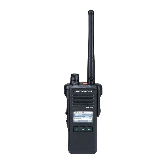
Page 162: Flashport
Introduction: Radio Description Radio Description The ASTRO APX 1000 radio provides improved voice quality across more coverage area. The digital process, called embedded signaling, intermixes system signaling information with digital voice, resulting in improved system reliability and the capability of supporting a multitude of advanced features. -
Page 163: Chapter 2 Basic Maintenance
General Maintenance In order to avoid operating outside the limits set by the FCC, align the ASTRO APX 1000 radio’s reference oscillator every time the radio is taken apart, or once per year, whichever comes first. (See Section 6.5.1). - Page 164 Basic Maintenance: Safe Handling of CMOS and LDMOS Devices • The APX 1000 radio has a vent port that allows for pressure equalization in the radio. Never poke this vent with any objects, such as needles, tweezers, or screwdrivers. This could create a leak path into the radio and a u t i o n the radio’s splash protection reliability will be lost.
-
Page 165: Chapter 3 Basic Theory Of Operation
ASTRO mode (digital) operation (12.5 kHz only), X2-TDMA mode (25 kHz only) and Phase 2 TDMA mode (12.5 kHz only). NOTE: The APX 1000 M1.5, M2 and M3 radio support Global Positioning System (GPS) but do not support Bluetooth, MACE and Accelerometer functions. As such, disregard all references to the functions mentioned above in “Chapter 3 Basic Theory of... -
Page 166: Major Assemblies
Basic Theory of Operation: Major Assemblies Major Assemblies The ASTRO APX 1000 radio includes the following major assemblies (See Figure 3-1.): • Main Board – Contains all transmit, receive, and frequency generation circuitry, including the digital receiver back-end IC and the reference oscillator. The main board also contains a dual... - Page 167 Basic Theory of Operation: Analog Mode of Operation Analog Mode of Operation This section provides an overview of the analog mode receive and transmit theory of operation. 3.2.1 Receiving The RF signal is received at the antenna and is routed through the Harmonic Filter, followed by the Antenna Switch and finally the 15dB Step Attenuator IC.
- Page 168 Basic Theory of Operation: Analog Mode of Operation Antenna 15 dB Step Switch Attenuator IF Filter ABACUS III Dec. ΣΔ ADC Filter Rx LO DIG_CTRL_ATTH 18Mhz Abacus III To GPS Diplexer Figure 3-4. Receiver Block Diagram (700/800 MHz) 3.2.1.1 GPS The GPS signal is tapped at the antenna port via a series resonant network (diplexer) which provides a very low capacitive load to the transceiver.
- Page 169 Basic Theory of Operation: Analog Mode of Operation 3.2.1.4 700/800 MHz Front-End From the 15 dB Step Attenuator, a 700/800 MHz band signal is routed to the first band SPST switch which selects the 700 or the 800 band signal and routes it to the appropriate first pre-selector filter. A second band select switch selects the output of the appropriate filter and applies it to an LNA followed by a similar pre-selector filter/ band-select switch circuit.
- Page 170 Basic Theory of Operation: Analog Mode of Operation 3.2.2.1 VHF Once a VHF frequency for transmit has been selected, the Trident IC and the accompanying logic circuitry will enable the voltage controlled oscillator which then generates the desired transmit frequency. This transmit signal is then routed to the TX buffer amplifier which amplifies the signal. The signal is routed to the VHF Driver amplifier and then to the discrete final power amplifier.
-
Page 171: Digital (Astro) Mode Of Operation
Basic Theory of Operation: Digital (ASTRO) Mode of Operation Digital (ASTRO) Mode of Operation In the ASTRO (digital) mode of operation, the transmitted or received signal is limited to a discrete set of frequency deviation levels. The receiver handles an ASTRO-mode signal identically to an analog-mode signal, up to the point where the DSP decodes the received data. - Page 172 Basic Theory of Operation: Controller Section The ARM controller core of the OMAP processor handles the power up sequence of all devices, including firmware upgrades, and all operating system tasks that are associated with FLASH and SDRAM memories and user interface communication. The FLASH memory (64 MB) is required to store the firmware, tuning, and Codeplug settings, which upon initialization get read and stored into SDRAM (32MB) for execution.
-
Page 173: Chapter 4 Recommended Test Equipment And Service Aids
The “Characteristics” column is included so that equivalent equipment may be substituted; however, when no information is provided in this column, the specific Motorola model listed is either a unique item or no substitution is recommended. -
Page 174: Service Aids
“Appendix B Replacement Parts Ordering”. While all of these items are available from Motorola, most are standard shop equipment items, and any equivalent item capable of the same performance may be substituted for the item listed. Table 4-2. Service Aids... -
Page 175: Chapter 5 Performance Checks
Chapter 5 Performance Checks This chapter covers performance checks used to ensure that the ASTRO APX 1000 radio meets published specifications. The recommended test equipment listed in the previous section approaches the accuracy of the manufacturing equipment, with a few exceptions. Accuracy of the test equipment must be maintained in compliance with the manufacturer’s recommended calibration... - Page 176 Performance Checks: Test Equipment Setup Initial equipment control settings should be as indicated in Table 5-1 and should be the same for all performance checks and alignment procedures, except as noted. Table 5-1. Initial Equipment Control Settings System Analyzer Test Set Power Supply Monitor Mode: Standard* Spkr/Load: Speaker...
-
Page 177: Display Radio Test Mode
Performance Checks: Display Radio Test Mode Display Radio Test Mode This section provides instructions for performing tests in display radio test mode. 5.2.1 Access the Test Mode To enter the display radio test mode: 1. Turn the radio on. 2. Within 10 seconds, press Side Button 2 five times in succession. The radio shows a series of displays that give information regarding various version numbers and subscriber specific information. - Page 178 5.2.2 RF Test Mode When the ASTRO APX 1000 radio is operating in its normal environment, the radio's microcomputer controls the RF channel selection, transmitter key-up, and receiver muting, according to the customer codeplug configuration. However, when the unit is on the bench for testing, alignment, or repair, it must be removed from its normal environment using a special routine, called RF TEST MODE.
- Page 179 Performance Checks: Display Radio Test Mode Table 5-3. Test Frequencies (MHz) – VHF, UHF1, UHF2, 700/800 MHz UHF1 UHF2 700/800 MHz Test Channel 136.075 136.025 380.075 380.025 450.075 450.025 764.0625 764.0125 142.075 142.125 390.075 390.025 460.075 460.025 769.0625 769.0125 154.275 154.225 400.075 400.025...
- Page 180 Performance Checks: Display Radio Test Mode 5.2.3 Control Top and Keypad Test Mode This test mode is used to verify proper operation of all radio buttons and switches if a failure is suspected. 5.2.3.1 Control Top Checks To perform the control top checks: 1.
-
Page 181: Receiver Performance Checks
Performance Checks: Receiver Performance Checks 5.2.4 RGB Test Mode To perform the RGB Color Test: 1. Press and release Top Button (Orange button) 2. Press any key; Crosstalk test patterns appears. 3. Press any key; White color test appears. 4. Press any key; Red color horizontal lines appears. 5. - Page 182 Performance Checks: Receiver Performance Checks Table 5-6. Receiver Tests for ASTRO Conventional Channels* Test Name System Analyzer Radio Test Set Comments Bit Error rate Mode: Proj 25 Std Radio Tuner PTT to OFF BER < 0.01% (BER) Floor RF Control: Gen Software (Bit Error (center) (Use test setup shown in...
-
Page 183: Transmitter Performance Checks
Performance Checks: Transmitter Performance Checks Transmitter Performance Checks The following tables outline the performance checks for the transmitter. Table 5-7. Transmitter Performance Checks – APX 1000 Test Name System Analyzer Radio Test Set Comments Reference RF Control: Monitor TEST MODE CSQ PTT to continuous VHF: ±2 ppm (272–348 Hz) - Page 184 5-10 Performance Checks: Transmitter Performance Checks Table 5-8. Transmitter Tests for ASTRO Conventional Channels – APX 1000 Test Name System Analyzer Radio Test Set Comments RF Power Mode: Proj 25 Std Radio Tuner PTT to continuous VHF: 1–5 Watt RF Control: Monitor Software not used.
-
Page 185: Chapter 6 Radio Alignment Procedures
Chapter 6 Radio Alignment Procedures This chapter describes both receiver and transmitter radio alignment procedures. Test Setup A personal computer (PC) and tuner software are required to align the radio. Refer to the applicable manual for installation and setup procedures for the software. To perform the alignment procedures, the radio must be connected to the PC and to a universal test set. - Page 186 Radio Alignment Procedures: Tuner Main Menu Tuner Main Menu › › › Select Tuner from the START menu by clicking Start Program Files Motorola › › ASTRO 25 Products ASTRO 25 Tuner. To read the radio, use the File Read Device menu or click on Figure 6-2 illustrates how the alignment screens are organized.
- Page 187 Radio Alignment Procedures: Softpot Figure 6-3. Typical Softpot Screen Adjusting the softpot value sends information to the radio to increase (or decrease) the voltage in the corresponding circuit. For example, left-clicking the UP spin button in the New Softpot Value scroll box on the Reference Oscillator screen instructs the radio’s microcomputer to increase the voltage across a varactor in the reference oscillator, which increases the frequency.
-
Page 188: Radio Information
Radio Alignment Procedures: Radio Information Radio Information Figure 6-4 shows a typical Radio Information screen. This screen is informational only and cannot be directly changed. Figure 6-4. Radio Information Screen Transmitter Alignments 6.5.1 Reference Oscillator Alignment Adjustment of the reference oscillator is critical for proper radio operation. Improper adjustment will result not only in poor operation, but also in a misaligned radio that will interfere with other users operating on adjacent channels. - Page 189 Radio Alignment Procedures: Transmitter Alignments This test can be done with either the R-2670 Communication Analyzer or the 8901_ Modulation Analyzer. • Initial setup using the R-2670 Communication Analyzer: - RF Control: Monitor - B/W: WB - Freq: CPS frequency under test - Attenuation: 20dB - Mon RF in: RF I/O - Meter: RF Display...
- Page 190 Radio Alignment Procedures: Transmitter Alignments Figure 6-6. Reference Oscillator Alignment Screen (UHF1) Figure 6-7. Reference Oscillator Alignment Screen (UHF2)
- Page 191 Radio Alignment Procedures: Transmitter Alignments Figure 6-8. Reference Oscillator Alignment Screen (700/800 MHz) 1. Make sure the Communication Analyzer is in Manual mode. • Set the base frequency to 173.925 MHz UHF1 • Set the base frequency to 469.925 MHz UHF2 •...
- Page 192 Radio Alignment Procedures: Transmitter Alignments Table 6-1. Reference Oscillator Alignment Band Target ±100 Hz UHF1 ±100 Hz UHF2 ±100 Hz 700/800 MHz ±100 Hz 3. Left-click the Program All button on the screen to dekey the radio and save the tuned values. 4.
- Page 193 Radio Alignment Procedures: Transmitter Alignments Figure 6-9. Transmit Power Characterization Points Alignment Screen (VHF) Figure 6-10. Transmit Power Characterization Points Alignment Screen (UHF1)
- Page 194 6-10 Radio Alignment Procedures: Transmitter Alignments Figure 6-11. Transmit Power Characterization Points Alignment Screen (UHF2) Figure 6-12. Transmit Power Characterization Points Alignment Screen (700/800MHz)
- Page 195 Radio Alignment Procedures: Transmitter Alignments 6-11 6.5.3 Power Characterization Tuning Tuning of the radio is done through Power Characterization tuning screen. IMPORTANT: Power Characterization Tuning Points must be tuned before tuning Power Characterization Tuning. NOTE: a.The longer the RF cable, the more the attenuation of the power reading. b.Use a standard 50 ohm cable.
- Page 196 6-12 Radio Alignment Procedures: Transmitter Alignments Figure 6-13. Transmit Power Characterization Alignment Screen (VHF) Figure 6-14. Transmit Power Characterization Alignment Screen (UHF1)
- Page 197 Radio Alignment Procedures: Transmitter Alignments 6-13 Figure 6-15. Transmit Power Characterization Alignment Screen (UHF2) Figure 6-16. Transmit Power Characterization Alignment Screen (700/800 MHz)
- Page 198 6-14 Radio Alignment Procedures: Transmitter Alignments 6.5.4 Transmit Deviation Balance Alignment This alignment procedure balances the modulation contributions of the low- and high-frequency portions of a baseband signal. Proper alignment is critical to the operation of signalling schemes that have very low frequency components (for example, DPL) and could result in distorted waveforms if improperly adjusted.
- Page 199 Radio Alignment Procedures: Transmitter Alignments 6-15 12. Repeat the steps 4 to 10 for all frequencies. 13. Left-click the Program All button on the screen to dekey the radio and save the tuned values. Figure 6-17. Transmit Deviation Balance Alignment Screen (VHF) Figure 6-18.
- Page 200 6-16 Radio Alignment Procedures: Transmitter Alignments Figure 6-19. Transmit Deviation Balance Alignment Screen (UHF2) Figure 6-20. Transmit Deviation Balance Alignment Screen (700/800 MHz)
-
Page 201: Front End Filter Alignment
Radio Alignment Procedures: Front End Filter Alignment 6-17 Front End Filter Alignment This procedure should only be attempted by qualified service technicians. a u t i o n The alignment procedure adjusts the front end receiver bandpass filters for the best receiver sensitivity and selectivity. -
Page 202: Performance Testing
6-18 Radio Alignment Procedures: Performance Testing Figure 6-22. Front End Filter Alignment Screen (UHF2) Performance Testing 6.7.1 Bit Error Rate This section describes the Bit Error Rate (BER) test of the radio’s receiver at a desired frequency (see Figure 6-23, Figure 6-24, Figure 6-25... - Page 203 Selecting External will route the same signal to the radio's accessory connector audio output. Selecting Mute will disable the audio output. NOTE: There will be no audio option available for APX 1000 when performing a Bit Error Rate Test.
- Page 204 6-20 Radio Alignment Procedures: Performance Testing Figure 6-23. Bit Error Rate Screen (VHF) Figure 6-24. Bit Error Rate Screen (UHF1)
- Page 205 Radio Alignment Procedures: Performance Testing 6-21 Figure 6-25. Bit Error Rate Screen (UHF2) Figure 6-26. Bit Error Rate Screen (700/800 MHz)
- Page 206 6-22 Radio Alignment Procedures: Performance Testing 6.7.2 Transmitter Test Pattern The Transmitter Test Pattern test is used to transmit specific test patterns at a desired frequency so that the user can perform tests on the radio’s transmitter (see Figure 6-27, Figure 6-28, Figure 6-29...
- Page 207 Radio Alignment Procedures: Performance Testing 6-23 Figure 6-28. Transmitter Test Pattern Screen (UHF1) Figure 6-29. Transmitter Test Pattern Screen (UHF2)
- Page 208 6-24 Radio Alignment Procedures: Performance Testing Figure 6-30. Transmitter Test Pattern Screen (700/800 MHz)
-
Page 209: Chapter 7 Disassembly/Reassembly Procedures
Items in parentheses ( ) throughout this chapter refer to item numbers in the exploded view diagrams and their associated parts lists. This chapter also has procedures for removing and installing the APX 1000 radio’s standard accessories. APX 1000 Exploded View (Main Subassemblies) - Page 210 Disassembly/Reassembly Procedures: APX 1000 Exploded View (Main Subassemblies) Figure 7-1. APX 1000 Partial Exploded View Table 7-1. APX 1000 Partial Exploded View Parts List Item Description Exploded View and Parts List Letter Figure 9-1 Front Kit Assembly Refer Figure 9-2...
-
Page 211: Required Tools And Supplies
Disassembly/Reassembly Procedures: Required Tools and Supplies Required Tools and Supplies Table 7-2. Required Tools and Supplies Motorola Supplier Tools Supplier Remarks Part Number Part Number Chassis Opener 66012028001 Motorola – To remove chassis from housing. Bit, Torx T6 – –... - Page 212 NOTE: The Motorola-approved battery shipped with the APX 1000 radio is uncharged. Prior to using a new battery, charge it per the recommended procedure for the battery. 1. With the radio turned off, lift up the latch located at the bottom of the battery.
- Page 213 Disassembly/Reassembly Procedures: Radio Disassembly 2. While lifting the latch, remove the battery by sliding it out as shown. Figure 7-3. Removing the Battery 7.4.2 Remove Antenna (7) 1. With the radio turned off, turn the antenna counter-clockwise to remove it from the radio. Figure 7-4.
- Page 214 Disassembly/Reassembly Procedures: Radio Disassembly 7.4.3 Remove Multi Function Knob (6) 1. Hold the radio with the top facing upward and the front of the radio facing you. 2. With the Chassis Opener, grasp the Multi Function Knob and pull it upward, until it is free from its shaft.
- Page 215 Disassembly/Reassembly Procedures: Radio Disassembly Thumb Screw with Hex Head Socket Figure 7-6. Removing the Thumb Screw 2. Slightly swing the Accessory-Connector Cover (1) away from radio before sliding it upward to disengage the hook feature. 3. Pull the Accessory-Connector Cover away from the radio. 7.4.5 Removal of the Back Kit Assembly (B) This section contains instructions for disassembling the radio.
- Page 216 Disassembly/Reassembly Procedures: Radio Disassembly 2. After the Chassis (26) is disengaged, slide the chassis assembly down and lift it away from the Front Kit (A) and lay both sub-assemblies on the anti-static mat (part of anti-static ground kit) as shown in Figure 7-8.
- Page 217 Disassembly/Reassembly Procedures: Radio Disassembly Figure 7-11. Lift up the Main Board from the Chassis When separating the small interconnects, care is needed to avoid damage to the interconnect and surrounding on-board a u t i o n components. Place the Main Board on the anti-static mat or in a clean and ESD safe area to avoid electrical damage to the electronics.
- Page 218 7-10 Disassembly/Reassembly Procedures: Radio Disassembly 7.4.5.4 Removal of the Shroud (32) 1. Place the black stick into the opening below the Shroud (32) to aid the disengagement of the Shroud. With the black stick still in place, slide the Shroud downwards at both sides to remove the Shroud from the Chassis (26).
- Page 219 Disassembly/Reassembly Procedures: Radio Disassembly 7-11 7.4.5.5 Removal of the Keypad Retainer (12) 1. Remove the four Keypad Retainer Screws (13) as shown in Figure 7-15. Keypad Retainer Screws Figure 7-15. Remove the Keypad Retainer Screws 2. Lift out the Keypad Retainer (12) from the Front Housing (2) as shown in Figure 7-16.
- Page 220 7-12 Disassembly/Reassembly Procedures: Radio Disassembly 7.4.5.6 Removal of the Keypad Board (10) and Keypad Flex (11) 1. With the Keypad Retainer (12) removed, gently detach the Keypad Flex (11) from the Keypad Board (10) as shown in Figure 7-17. When separating the flex and small interconnects, care is needed to avoid damage to the interconnect and surrounding a u t i o n on-board components...
- Page 221 Disassembly/Reassembly Procedures: Radio Disassembly 7-13 Figure 7-18. Remove the Keypad Board 7.4.5.7 Removal of the Keypad (8) 1. With the Keypad Board (10) removed, gently press the Keypad (8) from the front of the Front Housing (2) with fingers or with the aid of the back of the black stick to disengage the Keypad from the rib as shown in Figure 7-19.
-
Page 222: Serviceable Components Of The Main Sub-Assemblies
7-14 Disassembly/Reassembly Procedures: Serviceable Components of the Main Sub-Assemblies Figure 7-20. Remove the Keypad 7.4.6 Removal of the Front Kit Assembly (A) 1. Complete the steps in Section 7.4.5.1. Section 7.4.5.5. through Section 7.4.5.7. 2. With the steps completed, the Front Kit Assembly (A) is obtained. Serviceable Components of the Main Sub-Assemblies 7.5.1 Servicing Main Board Assembly... - Page 223 Disassembly/Reassembly Procedures: Serviceable Components of the Main Sub-Assemblies 7-15 7.5.1.1 Servicing Coin Cell: 1. Complete steps from Section 7.4.5.1. through Section 7.4.5.3. 2. Remove the coin cell with the Black Stick. NOTE: Make sure the positive side is facing upwards. 3.
- Page 224 7-16 Disassembly/Reassembly Procedures: Serviceable Components of the Main Sub-Assemblies 7.5.2 Servicing Chassis Assembly Microphone Membrane Microphone Boot Microphone Flex Back Microphone Backer Battery Connector Seal Ventilation Label Main O Ring Vacuum Port Seal Figure 7-22. Serviceable Components – Chassis Assembly 7.5.2.1 Servicing Ventilation Label: 1.
- Page 225 Disassembly/Reassembly Procedures: Serviceable Components of the Main Sub-Assemblies 7-17 7.5.2.2 Servicing Vacuum Port Seal: 1. Complete steps in Section 7.4. 2. Carefully peel off the seal. 3. Use the Black Stick to help remove any difficult sections of the seal. 4.
- Page 226 7-18 Disassembly/Reassembly Procedures: Serviceable Components of the Main Sub-Assemblies 7.5.2.6 Servicing Microphone Membrane: 1. Carefully remove the Microphone Membrane from the chassis opening using the Black Stick. 2. Use the pointed tip of the Black Stick to scrap off pieces of adhesives after removing the membrane.
- Page 227 Disassembly/Reassembly Procedures: Serviceable Components of the Main Sub-Assemblies 7-19 7.5.3.2 Servicing Back Label NOTE: There is no need to remove any component in order to service the Back Label. 1. Scrap off the Back Label with the Black Stick. 2. Clean the area once the Back Label is completely removed to ensure it is free of adhesive and debris.
- Page 228 7-20 Disassembly/Reassembly Procedures: Radio Reassembly Radio Reassembly This section contains instructions for reassembling the radio. 7.6.1 Reassemble the Keypad (8) 1. Gently lift the end of the Front Kit Flex to make way for the Keypad (8). While lifting the Front Kit Flex, care is needed to avoid excessive bending and damage to the Flex.
- Page 229 Disassembly/Reassembly Procedures: Radio Reassembly 7-21 7.6.2 Reassemble the Keypad Board (10) and Keypad Flex (11) 1. With the Keypad (8) assembled, gently lift the Front Kit Flex and place the Keypad Board (10) into the Front Housing. Figure 7-26. Plug in the Front Kit Flex Connector 2.
- Page 230 7-22 Disassembly/Reassembly Procedures: Radio Reassembly 7.6.3 Reassemble the Keypad Retainer (12) 1. Place the Keypad Retainer (12) over the Keypad Board (10) in the Front Housing (2) as shown in Figure 7-28. Figure 7-28. Place Keypad Retainer over the Keypad Board 2.
- Page 231 Disassembly/Reassembly Procedures: Radio Reassembly 7-23 7.6.4 Reassemble the Main Board (16) 1. Plug in the connectors from the Keypad Flex (11) and the Front Kit Flex onto the Main Board (16). With both the flexes connected to the Main Board, place the Main Board into the Chassis (25) as shown in Figure 7-30.
- Page 232 7-24 Disassembly/Reassembly Procedures: Radio Reassembly 3. Torque all seven Chassis Screws (15) with a Torx IP6 Bit and a Torque Driver to 3.7 in-lbf in the sequence as shown in Figure 7-32. Figure 7-32. Torque in the Keypad Retainer Screws 7.6.5 Reassemble the Shroud (32) 1.
- Page 233 Disassembly/Reassembly Procedures: Radio Reassembly 7-25 7.6.6 Reassemble the Main Subassemblies (A and B) 1. Complete the steps in Section 7.6.1. through Section 7.6.3. 2. Slide the Chassis assembly into the Front Housing as shown in Figure 7-34. Figure 7-34. Slide chassis assembly into Front Housing 3.
- Page 234 7-26 Disassembly/Reassembly Procedures: Radio Reassembly 7.6.7 Reassemble the Accessory-Connector Cover (1) 1. Insert the hooked end of the cover into the pocket. Engage the hook beneath the undercut and swing the cover down onto the radio. Ensure the cover is seated properly and the screw is aligned into the threaded hole.
- Page 235 Disassembly/Reassembly Procedures: Radio Reassembly 7-27 7.6.8 Reassemble Multi Function Knob (6) 1. Align the D-shaped part of the shaft with the D-shaped hole on the Multi Function knob. Press the knob into place. Figure 7-38. Reassemble the Multi Function Knob 7.6.9 Reassemble the Antenna (7) 1.
- Page 236 7-28 Disassembly/Reassembly Procedures: Radio Reassembly 7.6.10 Reassemble the Vacuum Port Seal (27), Ventilation Label (28) and Bottom Label (3) 1. Adhere and gently press the Vacuum Port Seal (27) on the chassis’ recess as shown in Figure 7-40. Figure 7-40. Assemble the Vacuum Port Seal 2.
- Page 237 Disassembly/Reassembly Procedures: Radio Reassembly 7-29 7.6.11 Reassemble the Battery (33) 1. With the radio turned off, slide up the battery into the radio’s frame until the bottom latch clicks into place as shown in Figure 7-43. Figure 7-43. Attaching Battery – Slide into Position...
-
Page 238: Ensuring Reliable Splash Protection
7.7.1 Standards ASTRO APX 1000 radio model meet the requirements of IP54, which require the radio to maintain water protection integrity when subjected to splashing of water with volumetric flow up to 10 liters per minute at pressure of 80–100 kPa from any direction for 5 minutes. - Page 239 Disassembly/Reassembly Procedures: Ensuring Reliable Splash Protection 7-31 7.7.5 Reassembly Do not reassemble the radio without first performing the following preliminary inspection procedure. a u t i o n Before reassembling the radio: 1. Inspect the Main O-Ring on the Chassis (26) for any damage or foreign material. 2.
- Page 240 7-32 Disassembly/Reassembly Procedures: Ensuring Reliable Splash Protection Notes...
-
Page 241: Chapter 8 Basic Troubleshooting
Level one and two troubleshooting will support only radio alignment, programming, battery replacement, and knob replacement, and circuit board replacement. Component-level service information can be found in the “ASTRO APX 1000 Portable Radios Detailed Service Manual,” Motorola publication number 68012004061. -
Page 242: Operational Error Codes
1E/10 Collaborative device is connected to the radio Contact your Motorola Sales but the collaborative feature is not enabled in Representative/Partner on how to the codeplug. add Collaborative feature to your radios. -
Page 243: Receiver Troubleshooting
Basic Troubleshooting: Receiver Troubleshooting Receiver Troubleshooting Table 8-3 lists the possible causes of, and corrections for, receiver problems. Table 8-3. Receiver Troubleshooting Chart Correction or Test Symptom Possible Cause (Measurements at Room Temperature) Radio Dead; Display Does Not 1. Dead Battery Replace with charged battery Turn On 2. -
Page 244: Transmitter Troubleshooting
Basic Troubleshooting: Transmitter Troubleshooting Transmitter Troubleshooting Table 8-4 lists the possible causes of, and corrections for, transmitter problems. Table 8-4. Transmitter Troubleshooting Chart Correction or Test (Measurements Symptom Possible Cause Taken at Room Temperature) No RF Power Out 1. TX Power Level or Frequency Check TX power level and frequency programming (from tuner) 2. -
Page 245: Chapter 9 Exploded Views And Parts Lists
Chapter 9 Exploded Views and Parts Lists This chapter contains exploded views and associated parts lists for the ASTRO APX 1000 digital portable radios. The following table lists the exploded views for the radio in different configurations: Table 9-1. APX 1000 Exploded Views and Controller Kit... - Page 246 Exploded Views and Parts Lists: APX 1000 Front Kit Exploded View APX 1000 Front Kit Exploded View Figure 9-1. APX 1000 Front Kit Exploded View...
- Page 247 Exploded Views and Parts Lists: APX 1000 Front Kit Exploded View Parts List APX 1000 Front Kit Exploded View Parts List Item Motorola Part Description Number 15012142001 Cover, Accessory-Connector † 0104059J79 Assembly, Front Housing Kit (Model 1.5) 0104061J96 Assembly, Front Housing Kit (Model 2)
- Page 248 Exploded Views and Parts Lists: APX 1000 Back Kit Exploded View 9.3APX 1000 Back Kit Exploded View Figure 9-2. APX 1000 Back Kit Exploded View...
- Page 249 Exploded Views and Parts Lists: APX 1000 Back Kit Exploded View Parts List APX 1000 Back Kit Exploded View Parts List Item Motorola Part Description Number 0386104Z10 Screw, Chassis 16† PMLD4613_ Assembly, Main Board (VHF) PMLE4952_ Assembly, Main Board (UHF_R1)
- Page 250 Exploded Views and Parts Lists: APX 1000 Back Kit Exploded View Parts List Notes...
-
Page 251: Index
Index Index controller theory of operation 3-7 Numerics disassembly/reassembly 700-800 MHz antenna model chart xiv attaching 7-27 radio specifications xviii removing 7-5 back chassis assembly removing 7-11 battery attaching 7-28 alignment, tuner removing 7-4 bit error rate test 6-18 expansion board assembly introduction 6-1 removing 7-8 main menu 6-2... - Page 252 Index-2 Index features 1-2 FLASHport feature 1-2 information screen 6-4 handling precautions model numbering system ix non-ruggedized radios 2-1 models 1-2 housing assembly reassembling reassembling 7-23 housing assembly 7-23 submergible models disassembling 7-30 reassembling 7-31 knobs and top bezel assembly submersibility removing 7-14 servicing 7-30...
- Page 253 Index Index-3 main menu 6-2 performance test 6-18 radio information screen 6-4 test equipment reference oscillator alignment 6-4 recommended 4-1 test setup 6-1 test mode, entering transmit deviation balance alignment 6-14 dual-display version 5-3 transmitter alignment 6-4 test setup transmitter test pattern 6-22 alignment 6-1 performance checks 5-1 tests...
- Page 254 Index-4 Index Notes...
- Page 255 Title Page ® ® ASTRO 1000 Digital Portable Radios Section 3 (900 MHz) APX 1000...
- Page 257 Table of Contents Model Numbering, Charts, and Specifications...........ix Portable Radio Model Numbering System ....................ix ASTRO APX 1000 900 MHz Model Chart ....................xi Specifications for APX 1000 900 MHz Radios ..................xii Chapter 1 Introduction ................. 1-1 Manual Contents..........................1-1 Notations Used in This Manual...................... 1-1 Radio Description ..........................
- Page 258 Exploded Views and Parts Lists ........9-1 APX 1000 Front Kit Exploded View ....................9-2 APX 1000 Front Kit Exploded View Parts List ................9-3 APX 1000 Back Kit Exploded View....................9-4 APX 1000 Back Kit Exploded View Parts List................9-5...
- Page 259 Receiver Tests for ASTRO Conventional Channels* ............5-8 Table 5-7. Transmitter Performance Checks – APX1000 ..............5-9 Table 5-8. Transmitter Tests for ASTRO Conventional Channels – APX 1000........5-10 Table 6-1. Reference Oscillator Alignment .................... 6-6 Table 7-1. APX 1000 Partial Exploded View Parts List ................7-2 Table 7-2.
- Page 260 List of Figures List of Figures Figure 3-1. APX 1000 Overall Block Diagram ..................3-2 Figure 3-2. Receiver Block Diagram (900 MHz)..................3-3 Figure 3-3. GPS Diagram ........................3-3 Figure 3-4. Transmitter (900 MHz) Block Diagram .................. 3-4 Figure 3-5. Controller Block Diagram ...................... 3-5 Figure 3-6.
- Page 261 Figure 7-43. Assemble the Ventilation Label................... 7-28 Figure 7-44. Assemble the Bottom Label ....................7-28 Figure 7-45. Attaching Battery – Slide into Position ................7-29 Figure 9-1. APX 1000 Front Kit Exploded View ..................9-2 Figure 9-2. APX 1000 Back Kit Exploded View..................9-4...
- Page 262 viii List of Figures Notes...
-
Page 263: Model Numbering, Charts, And Specifications
H = Hand-Held Portable SP Model Suffix Position 12 – Positions 2 & 3 – Model Series Unique Model Variations 84 = APX 1000 C = Cenelec N = Standard Package Position 4 - Frequency Band Position 11 – Version Less than 29.7MHz... - Page 264 Portable Radio Model Numbering System Notes...
-
Page 265: Astro Apx 1000 900 Mhz Model Chart
ASTRO APX 1000 900 MHz Model Chart ASTRO APX 1000 900 MHz Model Chart MODEL DESCRIPTION: 900 MHz, APX 1000 BT Models FCC ID: AZ489FT5864 H84WCF9PW6AN Model 2 APX1000, 896–941MHz, 1.0–3.9 Watts, Limited Keypad ITEM NUMBER DESCRIPTION PMLN5907_ Assembly, Front Kit, Model 2... -
Page 266: Specifications For Apx 1000 900 Mhz Radios
Specifications for APX 1000 900 MHz Radios Specifications for APX 1000 900 MHz Radios All specifications are per Telecommunications Industries Association TIA-603 unless otherwise noted. GENERAL RECEIVER TRANSMITTER Temperature Range: Frequency Range: 935–941 MHz Frequency Range: 896–902 MHz Operating: -30°C to +60°C 935–941 MHz... -
Page 267: Chapter 1 Introduction
Chapter 1 Introduction This manual contains information needed for Levels One and Two radio servicing. Level One servicing consists of radio programming, radio alignment, knobs replacement, and installation and removal of the antenna, belt clip, battery, and universal connector cover. Level Two servicing covers disassembly and reassembly of the radio to replace circuit boards. -
Page 268: Radio Description
® FLASHport The ASTRO APX1000 radio utilizes Motorola’s FLASHport technology. FLASHport makes it possible to add software that drives the radio’s capabilities both at the time of purchase and later on. Previously, changing a radio’s features and capabilities meant significant modifications or buying a new radio. -
Page 269: Chapter 2 Basic Maintenance
General Maintenance In order to avoid operating outside the limits set by the FCC, align the ASTRO APX 1000 radio’s reference oscillator every time the radio is taken apart, or once per year, whichever comes first. (See Section 6.5.1). - Page 270 Basic Maintenance: Safe Handling of CMOS and LDMOS Devices • The APX 1000 radio has a vent port that allows for pressure equalization in the radio. Never poke this vent with any objects, such as needles, tweezers, or screwdrivers. This could create a leak path into the radio and a u t i o n the radio’s splash protection reliability will be lost.
-
Page 271: Chapter 3 Basic Theory Of Operation
Chapter 3 Basic Theory of Operation This chapter discusses the basic operational theory of the ASTRO APX 1000 radio. The ASTRO APX 1000 radio, which is a single-band synthesized radio, is available in the 900 MHz (896–941 MHz) frequency band. -
Page 272: Major Assemblies
- Full Keypad Version has 3 soft keys, 4 direction Navigation key, 3x4 alphanumeric keypad, Home and Data buttons. External Accessory Bluetooth RF and GPS Connector Antenna Antenna Front Keypad Board Display Main Board Control Figure 3-1. APX 1000 Overall Block Diagram... -
Page 273: Analog Mode Of Operation
Basic Theory of Operation: Analog Mode of Operation Analog Mode of Operation This section provides an overview of the analog mode receive and transmit theory of operation. 3.2.1 Receiving The RF signal is received at the antenna and is routed through the Harmonic Filter, followed by the Antenna Switch and finally the 15dB Step Attenuator IC. - Page 274 Basic Theory of Operation: Analog Mode of Operation 3.2.1.3 Analog To Digital Converter The ADC IC's front end down converts the first IF to a second IF, a 2.25 MHz signal. The second IF is sampled at 18 MHz, a signal generated by an integrated clock synthesizer. The sampled signal is decimated by a factor of 900 to 20 kHz and converted to SSI format at the ADC's output.
-
Page 275: Digital (Astro) Mode Of Operation
Basic Theory of Operation: Digital (ASTRO) Mode of Operation Digital (ASTRO) Mode of Operation In the ASTRO (digital) mode of operation, the transmitted or received signal is limited to a discrete set of frequency deviation levels. The receiver handles an ASTRO-mode signal identically to an analog-mode signal, up to the point where the DSP decodes the received data. - Page 276 Basic Theory of Operation: Controller Section The ARM controller core of the OMAP processor handles the power up sequence of all devices, including firmware upgrades, and all operating system tasks that are associated with FLASH and SDRAM memories and user interface communication. The FLASH memory (64 MB) is required to store the firmware, tuning, and Codeplug settings, which upon initialization get read and stored into SDRAM (32MB) for execution.
- Page 277 Basic Theory of Operation: Controller Section Main Board GPS_Shutdown // 1 GPS/RF Antenna OMAP 1710 UART (GPS Tx/Rx) // 2 SSI (BT Audio) // 4 GPS SAW GPS/RF filters & Diplexer Misc Control // 7 USB // 2 BT Antenna // 38 128MB ATMEL AVR32...
- Page 278 Basic Theory of Operation: Controller Section Notes...
-
Page 279: Chapter 4 Recommended Test Equipment And Service Aids
The “Characteristics” column is included so that equivalent equipment may be substituted; however, when no information is provided in this column, the specific Motorola model listed is either a unique item or no substitution is recommended. -
Page 280: Service Aids
“Appendix B Replacement Parts Ordering”. While all of these items are available from Motorola, most are standard shop equipment items, and any equivalent item capable of the same performance may be substituted for the item listed. Table 4-2. Service Aids... -
Page 281: Chapter 5 Performance Checks
Chapter 5 Performance Checks This chapter covers performance checks used to ensure that the ASTRO APX 1000 radio meets published specifications. The recommended test equipment listed in the previous section approaches the accuracy of the manufacturing equipment, with a few exceptions. Accuracy of the test equipment must be maintained in compliance with the manufacturer’s recommended calibration... - Page 282 Performance Checks: Test Equipment Setup Initial equipment control settings should be as indicated in Table 5-1 and should be the same for all performance checks and alignment procedures, except as noted. Table 5-1. Initial Equipment Control Settings System Analyzer Test Set Power Supply Monitor Mode: Standard* Spkr/Load: Speaker...
-
Page 283: Display Radio Test Mode
Performance Checks: Display Radio Test Mode Display Radio Test Mode This section provides instructions for performing tests in display radio test mode. 5.2.1 Access the Test Mode To enter the display radio test mode: 1. Turn the radio on. 2. Within 10 seconds, press Side Button 2 five times in succession. The radio shows a series of displays that give information regarding various version numbers and subscriber specific information. - Page 284 Performance Checks: Display Radio Test Mode Table 5-2. Test-Mode Displays (Continued) Name of Display Description Appears FLASHcode The FLASH codes as programmed in the Always codeplug RF band 1 The radio’s operating frequency Always Tuning Ver Version of Tuning codeplug Always Proc Ver Version of Processor...
- Page 285 5.2.2 RF Test Mode When the ASTRO APX 1000 radio is operating in its normal environment, the radio's microcomputer controls the RF channel selection, transmitter key-up, and receiver muting, according to the customer codeplug configuration. However, when the unit is on the bench for testing, alignment, or repair, it must be removed from its normal environment using a special routine, called RF TEST MODE.
- Page 286 Performance Checks: Display Radio Test Mode Table 5-4. Test Environments Display Description Function Carrier RX: unsquelch if carrier detected Squelch TX: mic audio Tone RX: unsquelch if carrier and tone (192.8 Hz) Private-Line detected TX: mic audio + tone (192.8 Hz) ASTRO RX: none TX: Digital Voice...
-
Page 287: Receiver Performance Checks
Performance Checks: Receiver Performance Checks 5.2.4 RGB Test Mode To perform the RGB Color Test: 1. Press and release Top Button (Orange button) 2. Press any key; Crosstalk test patterns appears. 3. Press any key; White color test appears. 4. Press any key; Red color horizontal lines appears. 5. - Page 288 Performance Checks: Receiver Performance Checks Table 5-6. Receiver Tests for ASTRO Conventional Channels* Test Name System Analyzer Radio Test Set Comments Bit Error rate Mode: Proj 25 Std Radio Tuner PTT to OFF BER < 0.01% (BER) Floor RF Control: Gen Software (Bit Error (center) (Use test setup shown in...
-
Page 289: Transmitter Performance Checks
Performance Checks: Transmitter Performance Checks Transmitter Performance Checks The following tables outline the performance checks for the transmitter. Table 5-7. Transmitter Performance Checks – APX1000 Test Name System Analyzer Radio Test Set Comments Reference RF Control: Monitor TEST MODE CSQ PTT to continuous 900 MHz: ±1.5ppm Frequency... - Page 290 5-10 Performance Checks: Transmitter Performance Checks Table 5-8. Transmitter Tests for ASTRO Conventional Channels – APX 1000 Test Name System Analyzer Radio Test Set Comments RF Power Mode: Proj 25 Std Radio Tuner PTT to continuous 900 MHz: 1–2.5 Watt RF Control: Monitor Software not used.
-
Page 291: Chapter 6 Radio Alignment Procedures
Chapter 6 Radio Alignment Procedures This chapter describes both receiver and transmitter radio alignment procedures. Test Setup A personal computer (PC) and tuner software are required to align the radio. Refer to the applicable manual for installation and setup procedures for the software. To perform the alignment procedures, the radio must be connected to the PC and to a universal test set. -
Page 292: Tuner Main Menu
Radio Alignment Procedures: Tuner Main Menu Tuner Main Menu › › › Select Tuner from the START menu by clicking Start Program Files Motorola › › ASTRO 25 Products ASTRO 25 Tuner. To read the radio, use the File Read Device menu or click on Figure 6-2 illustrates how the alignment screens are organized. - Page 293 Radio Alignment Procedures: Softpot Figure 6-3. Typical Softpot Screen Adjusting the softpot value sends information to the radio to increase (or decrease) the voltage in the corresponding circuit. For example, left-clicking the UP spin button in the New Softpot Value scroll box on the Reference Oscillator screen instructs the radio’s microcomputer to increase the voltage across a varactor in the reference oscillator, which increases the frequency.
-
Page 294: Radio Information
Radio Alignment Procedures: Radio Information Radio Information Figure 6-4 shows a typical Radio Information screen. This screen is informational only and cannot be directly changed. Figure 6-4. Radio Information Screen... -
Page 295: Transmitter Alignments
Radio Alignment Procedures: Transmitter Alignments Transmitter Alignments 6.5.1 Reference Oscillator Alignment Adjustment of the reference oscillator is critical for proper radio operation. Improper adjustment will result not only in poor operation, but also in a misaligned radio that will interfere with other users operating on adjacent channels. - Page 296 Radio Alignment Procedures: Transmitter Alignments To align the reference oscillator: Select the Reference Oscillator alignment screen. See Figure 6-5. Figure 6-5. Reference Oscillator Alignment Screen (900 MHz) 1. Make sure the Communication Analyzer is in Manual mode. 900 MHz • Set the base frequency to 940.9375 MHz 2.
- Page 297 Radio Alignment Procedures: Transmitter Alignments 6.5.2 Power Characterization Points Tuning of the radio is done through Power Characterization Points tuning screen. 1. Select the TX Power Characterization Points alignment screen. See Figure 6-6. 2. Set power supply voltage and current limit. 3.
- Page 298 Radio Alignment Procedures: Transmitter Alignments 6.5.3 Power Characterization Tuning Tuning of the radio is done through Power Characterization tuning screen. IMPORTANT: Power Characterization Tuning Points must be tuned before tuning Power Characterization Tuning. NOTE: a.The longer the RF cable, the more the attenuation of the power reading. b.Use a standard 50 ohm cable.
- Page 299 Radio Alignment Procedures: Transmitter Alignments 6.5.4 PA Saturation Reference Tuning Tuning is done through PA Saturation Referencing screen. 1. Select the PA Saturation Reference alignment screen. The screen indicates the transmit frequencies to be used. See Figure 6-8. 2. In Manual Mode, set the service Monitor to the desired frequency (as shown in the frequency list in the PA Saturation Reference alignment screen).
- Page 300 6-10 Radio Alignment Procedures: Transmitter Alignments 6.5.5 Transmit Deviation Balance Alignment This alignment procedure balances the modulation contributions of the low- and high-frequency portions of a baseband signal. Proper alignment is critical to the operation of signalling schemes that have very low frequency components (for example, DPL) and could result in distorted waveforms if improperly adjusted.
- Page 301 Radio Alignment Procedures: Transmitter Alignments 6-11 11. Left-click the PTT Toggle to de-key the radio. 12. Repeat the steps 4 to 10 for all frequencies. 13. Left-click the Program All button on the screen to dekey the radio and save the tuned values. Figure 6-9.
-
Page 302: Performance Testing
Selecting External will route the same signal to the radio's accessory connector audio output. Selecting Mute will disable the audio output. NOTE: There will be no audio option available for APX 1000 when performing a Bit Error Rate Test. - Page 303 Radio Alignment Procedures: Performance Testing 6-13 • BER Integration Time: BER Integration Time carries with Test Pattern Type. • Number of Frames Number of Frames over which bit error result are accumulated to produce the result. NOTE: When Continuous Operation = Yes, all fields will be grayed out while the test is in progress. They will be enabled when the STOP button is pressed.
- Page 304 6-14 Radio Alignment Procedures: Performance Testing 6.6.2 Transmitter Test Pattern The Transmitter Test Pattern test is used to transmit specific test patterns at a desired frequency so that the user can perform tests on the radio’s transmitter (see Figure 6-11). 6.6.2.1 Transmitter Test Fields This screen contains the following fields: •...
-
Page 305: Chapter 7 Disassembly/Reassembly Procedures
Items in parentheses ( ) throughout this chapter refer to item numbers in the exploded view diagrams and their associated parts lists. This chapter also has procedures for removing and installing the APX 1000 radio’s standard accessories. APX 1000 Exploded View (Main Subassemblies) - Page 306 Disassembly/Reassembly Procedures: APX 1000 Exploded View (Main Subassemblies) Figure 7-1. APX 1000 Partial Exploded View Table 7-1. APX 1000 Partial Exploded View Parts List Item Description Exploded View and Parts List Letter Figure 9-1 Front Kit Assembly Refer Figure 9-2...
-
Page 307: Required Tools And Supplies
Disassembly/Reassembly Procedures: Required Tools and Supplies Required Tools and Supplies Table 7-2. Required Tools and Supplies Motorola Supplier Tools Supplier Remarks Part Number Part Number Chassis Opener 66012028001 Motorola – To remove chassis from housing. Bit, Torx T6 – –... -
Page 308: Radio Disassembly
NOTE: The Motorola-approved battery shipped with the APX 1000 radio is uncharged. Prior to using a new battery, charge it per the recommended procedure for the battery. 1. With the radio turned off, lift up the latch located at the bottom of the battery. - Page 309 Disassembly/Reassembly Procedures: Radio Disassembly 2. While lifting the latch, remove the battery by sliding it out as shown. Figure 7-3. Removing the Battery 7.4.2 Remove Antenna (23) 1. With the radio turned off, turn the antenna counter-clockwise to remove it from the radio. Figure 7-4.
- Page 310 Disassembly/Reassembly Procedures: Radio Disassembly 7.4.3 Remove Multi Function Knob (22) 1. Hold the radio with the top facing upward and the front of the radio facing you. 2. With the Chassis Opener, grasp the Multi Function Knob and pull it upward, until it is free from its shaft.
- Page 311 Disassembly/Reassembly Procedures: Radio Disassembly 7.4.4 Remove Accessory-Connector Cover (14) When the accessory connector is not in use, keep it covered with the Accessory-Connector Cover. a u t i o n 1. Unscrew the thumb screw. If the screw is too tight, use an Allen wrench. NOTE: Do not remove the screw.
- Page 312 Disassembly/Reassembly Procedures: Radio Disassembly 7.4.5 Removal of the Back Kit Assembly ( This section contains instructions for disassembling the radio. 7.4.5.1 Removal of the Chassis (40) 1. With the Battery removed, disengage the Chassis (40) using the Chassis Opener as shown in Figure 7-7.
- Page 313 Disassembly/Reassembly Procedures: Radio Disassembly 7.4.5.2 Removal of the Secondary Shield Assembly (31) 1. Remove the chassis screws (29) as shown in Figure 7-9. Figure 7-9. Remove the chassis screws 2. With the chassis screws removed, lift the Secondary Shield Assembly (31) out from the Chassis (40) as shown in Figure 7-10.
- Page 314 7-10 Disassembly/Reassembly Procedures: Radio Disassembly 7.4.5.3 Removal of the Main Board (32) 1. Remove the Main O-Ring (35) at the antenna holder as shown in Figure 7-11. Antenna Holder Figure 7-11. Remove the Main O-Ring at the antenna holder 2. Lift up the Main Board (32) from the Chassis (40) towards the Front Housing (16) and gently unplug the connectors from the Back Kit Flex (30) to remove the Main Board as shown in Figure 7-12.
- Page 315 Disassembly/Reassembly Procedures: Radio Disassembly 7-11 Back Kit Flex Connectors Figure 7-13. Unplug the Back Kit Flex connectors 7.4.5.4 Removal of the Shroud (46) 1. Place the black stick into the opening below the Shroud (46) to aid the disengagement of the Shroud.
- Page 316 7-12 Disassembly/Reassembly Procedures: Radio Disassembly 7.4.5.5 Removal of the Keypad Retainer (27) 1. With the Back Kit Flex (33) connectors unplugged from the Main Board (32) as shown in Figure 7-13., remove the Keypad Retainer Screws (28) as shown in Figure 7-16.
- Page 317 Disassembly/Reassembly Procedures: Radio Disassembly 7-13 7.4.5.6 Removal of the Keypad Board (26) 1. With the Keypad Retainer (27) removed, gently unplug the connectors of the Front Kit flex (2) and Back Kit Flex (30) to remove the Keypad Board (26) as shown in Figure 7-18.
- Page 318 7-14 Disassembly/Reassembly Procedures: Radio Disassembly 7.4.5.7 Removal of the Keypad (24) 1. With the Keypad Board (26) removed, gently press the Keypad (24) from the front of the Front Housing (16) with fingers or with the aid of the back of the black stick to disengage the Keypad from the rib as shown in Figure 7-20.
-
Page 319: Serviceable Components Of The Main Sub-Assemblies
Disassembly/Reassembly Procedures: Serviceable Components of the Main Sub-Assemblies 7-15 7.4.6 Removal of the Front Kit Assembly (A) 1. Complete the steps in Section 7.4.5.1. Section 7.4.5.5. through Section 7.4.5.7. 2. With the steps completed, the Front Kit Assembly (A) is obtained. Serviceable Components of the Main Sub-Assemblies 7.5.1 Servicing Main Board Assembly... - Page 320 7-16 Disassembly/Reassembly Procedures: Serviceable Components of the Main Sub-Assemblies 7.5.2 Servicing Chassis Assembly Microphone Membrane Microphone Boot Microphone Flex Back Microphone Backer Battery Connector Seal Ventilation Label Vacuum Port Seal Main O Ring Figure 7-23. Serviceable Components – Chassis Assembly 7.5.2.1 Servicing Ventilation Label: 1.
- Page 321 Disassembly/Reassembly Procedures: Serviceable Components of the Main Sub-Assemblies 7-17 7.5.2.2 Servicing Vacuum Port Seal: 1. Complete steps in Section 7.4. 2. Carefully peel off the seal. 3. Use the Black Stick to help remove any difficult sections of the seal. 4.
- Page 322 7-18 Disassembly/Reassembly Procedures: Serviceable Components of the Main Sub-Assemblies 7.5.2.6 Servicing Microphone Membrane: 1. Carefully remove the Microphone Membrane from the chassis opening using the Black Stick. 2. Use the pointed tip of the Black Stick to scrap off pieces of adhesives after removing the membrane.
- Page 323 Disassembly/Reassembly Procedures: Serviceable Components of the Main Sub-Assemblies 7-19 7.5.3.2 Servicing Back Label NOTE: There is no need to remove any component in order to service the Back Label. 1. Scrap off the Back Label with the Black Stick. 2. Clean the area once the Back Label is completely removed to ensure it is free of adhesive and debris.
-
Page 324: Radio Reassembly
7-20 Disassembly/Reassembly Procedures: Radio Reassembly Radio Reassembly This section contains instructions for reassembling the radio. 7.6.1 Reassemble the Main Board (32) 1. Plug in the connectors of the Back Kit Flex (30) onto the Main Board (32). With the Back Kit Flex connected to the Main Board, place the Main Board into the Chassis (40) as shown in Figure 7-26. - Page 325 Disassembly/Reassembly Procedures: Radio Reassembly 7-21 7.6.2 Reassemble the Secondary Shield Assembly (31) 1. With the Main Board (32) assembled, place the Secondary Shield Assembly (31) onto the Main Board. Secondary Shield’s Dimples Figure 7-28. Assemble the Secondary Shield Assembly 2. Torque all seven Chassis Screws (29) with a Torx IP6 Bit and a Torque Driver to 3.0 in-lbf in the sequence as shown in Figure 7-29.
- Page 326 7-22 Disassembly/Reassembly Procedures: Radio Reassembly 7.6.3 Reassemble the Keypad (24) 1. Place the Keypad (24) into the Front Housing (16) and gently flush the mushroom rib at the edges of the Keypad into the Front Housing with the aid of the back of the Black Stick. When flushing the Keypad, care is needed to avoid damage to the Keypad.
- Page 327 Disassembly/Reassembly Procedures: Radio Reassembly 7-23 7.6.4 Reassemble the Keypad Board (26) 1. With the Keypad (24) assembled, place the Keypad Board (26) into the Front Housing (16). 2. Plug in the connector of the Front Kit Flex (2) as shown in Figure 7-31.
- Page 328 7-24 Disassembly/Reassembly Procedures: Radio Reassembly 7.6.5 Reassemble the Keypad Retainer (27) 1. Place the Keypad Retainer (27) over the Keypad Board (26) in the Front Housing (16) as shown in Figure 7-33. Figure 7-33. Place Keypad Retainer over the Keypad Board 2.
- Page 329 Disassembly/Reassembly Procedures: Radio Reassembly 7-25 7.6.6 Reassemble the Shroud (46) 1. Slide the Shroud (46) into the Chassis’ frame until the latch clicks into place as shown in Figure 7-35. Figure 7-35. Assemble the Shroud 7.6.7 Reassemble the Main Subassemblies (A and B) 1.
- Page 330 7-26 Disassembly/Reassembly Procedures: Radio Reassembly 7.6.8 Reassemble the Accessory-Connector Cover (14) 1. Insert the hooked end of the cover into the pocket. Engage the hook beneath the undercut and swing the cover down onto the radio. Ensure the cover is seated properly and the screw is aligned into the threaded hole.
- Page 331 Disassembly/Reassembly Procedures: Radio Reassembly 7-27 7.6.9 Reassemble Multi Function Knob (22) 1. Align the D-shaped part of the shaft with the D-shaped hole on the Multi Function knob. Press the knob into place. Figure 7-40. Reassemble the Multi Function Knob 7.6.10 Reassemble the Antenna (23) 1.
- Page 332 7-28 Disassembly/Reassembly Procedures: Radio Reassembly 7.6.11 Reassemble the Vacuum Port Seal (42), Ventilation Label (43) and Bottom Label (17) 1. Adhere and gently press the Vacuum Port Seal (42) on the chassis’ recess as shown in Figure 7-42. Figure 7-42. Assemble the Vacuum Port Seal 2.
- Page 333 Disassembly/Reassembly Procedures: Radio Reassembly 7-29 7.6.12 Reassemble the Battery (47) 1. With the radio turned off, slide up the battery into the radio’s frame until the bottom latch clicks into place as shown in Figure 7-45. Figure 7-45. Attaching Battery – Slide into Position...
-
Page 334: Ensuring Reliable Splash Protection
7.7.1 Standards ASTRO APX 1000 radio model meet the requirements of IP54, which require the radio to maintain water protection integrity when subjected to splashing of water with volumetric flow up to 10 liters per minute at pressure of 80–100 kPa from any direction for 5 minutes. - Page 335 Disassembly/Reassembly Procedures: Ensuring Reliable Splash Protection 7-31 7.7.5 Reassembly Do not reassemble the radio without first performing the following preliminary inspection procedure. a u t i o n Before reassembling the radio: 1. Inspect the Main O-Ring on the Chassis (26) for any damage or foreign material. 2.
- Page 336 7-32 Disassembly/Reassembly Procedures: Ensuring Reliable Splash Protection Notes...
-
Page 337: Chapter 8 Basic Troubleshooting
Level one and two troubleshooting will support only radio alignment, programming, battery replacement, and knob replacement, and circuit board replacement. Component-level service information can be found in the “ASTRO APX 1000 Portable Radios Detailed Service Manual,” Motorola publication number 68012004061. -
Page 338: Operational Error Codes
1E/10 Collaborative device is connected to the radio Contact your Motorola Sales but the collaborative feature is not enabled in Representative/Partner on how to the codeplug. add Collaborative feature to your radios. -
Page 339: Receiver Troubleshooting
Basic Troubleshooting: Receiver Troubleshooting Receiver Troubleshooting Table 8-3 lists the possible causes of, and corrections for, receiver problems. Table 8-3. Receiver Troubleshooting Chart Correction or Test Symptom Possible Cause (Measurements at Room Temperature) Radio Dead; Display Does Not 1. Dead Battery Replace with charged battery Turn On 2. -
Page 340: Transmitter Troubleshooting
Basic Troubleshooting: Transmitter Troubleshooting Transmitter Troubleshooting Table 8-4 lists the possible causes of, and corrections for, transmitter problems. Table 8-4. Transmitter Troubleshooting Chart Correction or Test (Measurements Symptom Possible Cause Taken at Room Temperature) No RF Power Out 1. TX Power Level or Frequency Check TX power level and frequency programming (from tuner) 2. -
Page 341: Chapter 9 Exploded Views And Parts Lists
Chapter 9 Exploded Views and Parts Lists This chapter contains exploded views and associated parts lists for the ASTRO APX 1000 digital portable radios. The following table lists the exploded views for the radio in different configurations: Table 9-1. APX 1000 Exploded Views and Controller Kit... - Page 342 Exploded Views and Parts Lists: APX 1000 Front Kit Exploded View APX 1000 Front Kit Exploded View Front Kit Assembly PMLN5907_ (Model 2) Figure 9-1. APX 1000 Front Kit Exploded View...
-
Page 343: Apx 1000 Front Kit Exploded View Parts List
Exploded Views and Parts Lists: APX 1000 Front Kit Exploded View Parts List APX 1000 Front Kit Exploded View Parts List Item Motorola Part Description Number †† 0386104Z04 Screw, Retainer, Speaker † 0104043J28 Assembly, Flex, Front Kit † 42012055001 Retainer, LCD †... -
Page 344: Apx 1000 Back Kit Exploded View
Exploded Views and Parts Lists: APX 1000 Back Kit Exploded View APX 1000 Back Kit Exploded View Figure 9-2. APX 1000 Back Kit Exploded View... -
Page 345: Apx 1000 Back Kit Exploded View Parts List
Exploded Views and Parts Lists: APX 1000 Back Kit Exploded View Parts List APX 1000 Back Kit Exploded View Parts List Item Motorola Part Description Number 0386104Z04 Screw, Chassis 0104043J76 Assembly, Flex, Back-kit (Model 2 ) 0104046J48 Shield, Secondary Assembly †... - Page 346 Exploded Views and Parts Lists: APX 1000 Back Kit Exploded View Parts List Notes...
- Page 347 Index Index disassembly/reassembly antenna attaching 7-27 removing 7-5 back chassis assembly alignment, tuner removing 7-12 bit error rate test 6-12 battery introduction 6-1 attaching 7-28 main menu 6-2 removing 7-4 radio information screen 6-4 expansion board assembly reference oscillator 6-5 removing 7-10 softpot use 6-2 housing assembly...
- Page 348 Index-2 Index housing assembly submergible models reassembling 7-20 disassembling 7-30 reassembling 7-31 submersibility servicing 7-30 standards 7-30 knobs and top bezel assembly test environments 5-6 assemble 7-21 test frequencies 5-5 removing 7-15 test mode dual-display version 5-3 receiver ASTRO conventional channel tests 5-8 performance checks 5-7 main housing assembly troubleshooting 8-3...
- Page 349 Index Index-3 ASTRO conventional channels 5-8 radio information screen 6-4 performance checks 5-7 reference oscillator alignment 6-5 transmitter test setup 6-1 ASTRO conventional channels 5-10 transmit deviation balance alignment 6-10 performance checks 5-9 transmitter alignment 6-5 theory of operation transmitter test pattern 6-14 analog mode 3-3 ASTRO mode 3-5 controller 3-5...
-
Page 350: Index
Index-4 Index Notes... - Page 351 Title Page ® ® ® ® ASTRO 2000/ APX 4000 Digital Portable Radios Section 4 APX 2000/ APX 4000 (Two Knobs)
- Page 352 Notes...
- Page 353 Table of Contents Table of Contents Model Numbering, Charts, and Specifications...........ix Portable Radio Model Numbering System ....................ix ASTRO APX 2000/ APX 4000 (Two Knobs) VHF Model Chart..............xi ASTRO APX 2000/ APX 4000 (Two Knobs) VHF Model Chart (Continued)..........xii ASTRO APX 2000/ APX 4000 (Two Knobs) UHF1 Model Chart ............. xiii ASTRO APX 2000/ APX 4000 (Two Knobs) UHF1 Model Chart (Continued)..........
- Page 354 Table of Contents Chapter 5 Performance Checks ............5-1 Test Equipment Setup ........................5-1 Display Radio Test Mode....................... 5-3 Receiver Performance Checks ...................... 5-7 Transmitter Performance Checks ....................5-10 Chapter 6 Radio Alignment Procedures..........6-1 Test Setup............................6-1 Tuner Main Menu........................... 6-2 Softpot............................
- Page 355 Warranty and Service Support.......................B-1 European Radio Support Centre (ERSC) ..................B-2 Piece Parts ............................B-2 Technical Support..........................B-3 Further Assistance From Motorola ....................B-3 Appendix C LACR Replacement Parts Ordering and Motorola Service Centers ....................C-1 Commercial Warranty ........................C-1 Limited Warranty ............................1 MOTOROLA COMMUNICATION PRODUCTS ................1 I.
- Page 356 List of Tables List of Tables Table 1-1. ASTRO APX 2000/ APX 4000 (Two Knobs) Basic Features ..........1-2 Table 4-1. Recommended Test Equipment .................... 4-1 Table 4-2. Service Aids .......................... 4-2 Table 5-1. Initial Equipment Control Settings ..................5-2 Table 5-2.
- Page 357 List of Figures List of Figures Figure 3-1. APX 2000/ APX 4000 (Two Knobs) Overall Block Diagram..........3-2 Figure 3-2. Receiver Block Diagram (VHF)..................... 3-3 Figure 3-3. Receiver Block Diagram (UHF1/UHF2) ................3-3 Figure 3-4. Receiver Block Diagram (700/800 MHz)................3-4 Figure 3-5.
- Page 358 viii List of Figures Figure 8-6. Removing the Channel Knob ....................8-7 Figure 8-7. Removing the Thumb Screw....................8-8 Figure 8-8. Unscrew the screws ......................8-9 Figure 8-9. Removing the Volume Switch Spanner Nut ................8-9 Figure 8-10. Disengage the Chassis ....................... 8-10 Figure 8-11.
-
Page 359: Model Numbering, Charts, And Specifications
Portable Radio Model Numbering System Model Numbering, Charts, and Specifications Portable Radio Model Numbering System Typical Model Number: Position: 12 13 Position 1 – Type of Unit Positions 13 – 16 H = Hand-Held Portable SP Model Suffix Position 12 – Positions 2 &... - Page 360 Portable Radio Model Numbering System Notes...
-
Page 361: Astro Apx 2000/ Apx 4000 (Two Knobs) Vhf Model Chart
ASTRO APX 2000/ APX 4000 (Two Knobs) VHF Model Chart ASTRO APX 2000/ APX 4000 (Two Knobs) VHF Model Chart MODEL DESCRIPTION: 136–174 MHz, APX 4000_2000 FCC ID: AZ489FT3828 H51KDF9PW6AN APX 4000 Model 2 VHF H52KDF9PW6AN APX 2000 Model 2 VHF H51KDH9PW7AN APX 4000 Model 3 VHF H52KDH9PW7AN... -
Page 362: Astro Apx 2000/ Apx 4000 (Two Knobs) Vhf Model Chart (Continued)
Option available. Can be serviced in depot and ordered thru AAD. O Option available. Can be serviced in depot and orderable by UL qualified customers/dealers only. For APAC – Only UL label can be replaced and purchased by Motorola. Appendix A •... -
Page 363: Astro Apx 2000/ Apx 4000 (Two Knobs) Uhf1 Model Chart
ASTRO APX 2000/ APX 4000 (Two Knobs) UHF1 Model Chart xiii ASTRO APX 2000/ APX 4000 (Two Knobs) UHF1 Model Chart MODEL DESCRIPTION: 380–470 MHz, APX 4000_2000 FCC ID: AZ489FT4905 H51QDF9PW6AN APX 4000 Model 2 UHF1 H52QDF9PW6AN APX 2000 Model 2 UHF1 H51QDH9PW7AN APX 4000 Model 3 UHF1 H52QDH9PW7AN... -
Page 364: Astro Apx 2000/ Apx 4000 (Two Knobs) Uhf1 Model Chart (Continued)
Option available. Can be serviced in depot and ordered thru AAD. O Option available. Can be serviced in depot and orderable by UL qualified customers/dealers only. For APAC – Only UL label can be replaced and purchased by Motorola. Appendix A •... -
Page 365: Astro Apx 2000/ Apx 4000 (Two Knobs) Uhf2 Model Chart
ASTRO APX 2000/ APX 4000 (Two Knobs) UHF2 Model Chart ASTRO APX 2000/ APX 4000 (Two Knobs) UHF2 Model Chart MODEL DESCRIPTION: 450–520MHz, APX 4000_2000 FCC ID: AZ489FT4910 H51SDF9PW6AN APX 4000 Model 2 UHF2 H52SDF9PW6AN APX 2000 Model 2 UHF2 H51SDH9PW7AN APX 4000 Model 3 UHF2 H52SDH9PW7AN... -
Page 366: Astro Apx 2000/ Apx 4000 (Two Knobs) Uhf2 Model Chart (Continued)
Option available. Can be serviced in depot and ordered thru AAD. O Option available. Can be serviced in depot and orderable by UL qualified customers/dealers only. For APAC – Only UL label can be replaced and purchased by Motorola. Appendix A •... -
Page 367: Astro Apx 2000/ Apx 4000 (Two Knobs) 700/800 Mhz Model Chart
ASTRO APX 2000/ APX 4000 (Two Knobs) 700/800 MHz Model Chart xvii ASTRO APX 2000/ APX 4000 (Two Knobs) 700/800 MHz Model Chart MODEL DESCRIPTION: 764–870 MHz,APX 4000_2000 FCC ID: AZ489FT7049 H51UCF9PW6AN APX 4000 Model 2 7/800 H52UCF9PW6AN APX 2000 Model 2 7/800 H51UCH9PW7AN APX 4000 Model 3 7/800 H52UCH9PW7AN... -
Page 368: Astro Apx 2000/ Apx 4000 (Two Knobs) 700/800 Mhz Model Chart (Continued)
Option available. Can be serviced in depot and ordered thru AAD. O Option available. Can be serviced in depot and orderable by UL qualified customers/dealers only. For APAC – Only UL label can be replaced and purchased by Motorola. Appendix A •... -
Page 369: Specifications For Apx 2000/ Apx 4000 (Two Knobs) Vhf Radios
Specifications for APX 2000/ APX 4000 (Two Knobs) VHF Radios Specifications for APX 2000/ APX 4000 (Two Knobs) VHF Radios All specifications are per Telecommunications Industries Association TIA-603 unless otherwise noted. GENERAL RECEIVER TRANSMITTER Temperature Range: Frequency Range: 136–174 MHz Frequency Range: 136–174 MHz Operating:... -
Page 370: Specifications For Apx 2000/ Apx 4000 (Two Knobs) Uhf1 Radios
Specifications for APX 2000/ APX 4000 (Two Knobs) UHF1 Radios Specifications for APX 2000/ APX 4000 (Two Knobs) UHF1 Radios All specifications are per Telecommunications Industries Association TIA-603 unless otherwise noted. GENERAL RECEIVER TRANSMITTER Temperature Range: Frequency Range: 380–470 MHz Frequency Range: 380–470 MHz Operating:... -
Page 371: Specifications For Apx 2000/ Apx 4000 (Two Knobs) Uhf2 Radios
Specifications for APX 2000/ APX 4000 (Two Knobs) UHF2 Radios Specifications for APX 2000/ APX 4000 (Two Knobs) UHF2 Radios All specifications are per Telecommunications Industries Association TIA-603 unless otherwise noted. GENERAL RECEIVER TRANSMITTER Temperature Range: Frequency Range: 450–520 MHz Frequency Range: 450–520 MHz Operating:... -
Page 372: Specifications For Apx 2000/ Apx 4000 (Two Knobs) 700/800 Mhz Radios
xxii Specifications for APX 2000/ APX 4000 (Two Knobs) 700/800 MHz Radios Specifications for APX 2000/ APX 4000 (Two Knobs) 700/800 MHz Radios All specifications are per Telecommunications Industries Association TIA-603 unless otherwise noted. GENERAL RECEIVER TRANSMITTER Temperature Range: Frequency Range: Frequency Range: Operating: -30°C to +60°C... -
Page 373: Chapter 1 Introduction
Chapter 1 Introduction This manual contains information needed for Levels One and Two radio servicing. Level One servicing consists of radio programming, radio alignment, knobs replacement, and installation and removal of the antenna, belt clip, battery, and universal connector cover. Level Two servicing covers disassembly and reassembly of the radio to replace circuit boards. -
Page 374: Radio Description
® FLASHport The ASTRO APX 2000/ APX 4000 (Two Knobs) radio utilizes Motorola’s FLASHport technology. FLASHport makes it possible to add software that drives the radio’s capabilities both at the time of purchase and later on. Previously, changing a radio’s features and capabilities meant significant modifications or buying a new radio. -
Page 375: Chapter 2 Basic Maintenance
Chapter 2 Basic Maintenance This chapter describes the preventive maintenance and handling precautions. Each of these topics provides information vital to the successful operation and maintenance of the radio. General Maintenance In order to avoid operating outside the limits set by the FCC, align the ASTRO APX 2000/ APX 4000 (Two Knobs) radio’s reference oscillator every time the radio is taken apart, or once per year, whichever comes first. - Page 376 Basic Maintenance: Safe Handling of CMOS and LDMOS Devices • The APX 2000/ APX 4000 (Two Knobs) radio has a vent port that allows for pressure equalization in the radio. Never poke this vent with any objects, such as needles, tweezers, or screwdrivers. This could create a a u t i o n leak path into the radio and the radio’s submergibility will be lost.
-
Page 377: Chapter 3 Basic Theory Of Operation
Chapter 3 Basic Theory of Operation This chapter discusses the basic operational theory of the ASTRO APX 2000/ APX 4000 (Two Knobs) radio. The ASTRO APX 2000/ APX 4000 (Two Knobs) radio, which is a single-band synthesized radio, is available in the following frequency bands. •... -
Page 378: Major Assemblies
Basic Theory of Operation: Major Assemblies Major Assemblies The ASTRO APX 2000/ APX 4000 (Two Knobs) radio includes the following major assemblies (See Figure 3-1.): • Main Board – Contains all transmit, receive, and frequency generation circuitry, including the digital receiver back-end IC and the reference oscillator. The main board also contains a dual core processor, which includes both the microcontroller unit (MCU) and a digital signal processor (DSP) core, the processors's memory devices, an audio and power supply support integrated circuit (IC), a digital support IC, external power amplifier as well as combination... -
Page 379: Analog Mode Of Operation
Basic Theory of Operation: Analog Mode of Operation Analog Mode of Operation This section provides an overview of the analog mode receive and transmit theory of operation. 3.2.1 Receiving The RF signal is received at the antenna and is routed through the Harmonic Filter, followed by the antenna Switch and finally the 15dB Step Attenuator IC. - Page 380 Basic Theory of Operation: Analog Mode of Operation Antenna 15 dB Step Switch Attenuator IF Filter ABACUS III Dec. ΣΔ ADC Filter Rx LO DIG_CTRL_ATTH 18Mhz Abacus III To GPS Diplexer Figure 3-4. Receiver Block Diagram (700/800 MHz) 3.2.1.1 GPS The GPS signal is tapped at the antenna port via a series resonant network (diplexer) which provides a very low capacitive load to the transceiver.
- Page 381 Basic Theory of Operation: Analog Mode of Operation 3.2.1.4 700/800 MHz Front-End From the 15 dB Step Attenuator, a 700/800 MHz band signal is routed to the first band SPST switch which selects the 700 or the 800 band signal and routes it to the appropriate first pre-selector filter. A second band select switch selects the output of the appropriate filter and applies it to an LNA followed by a similar pre-selector filter/ band-select switch circuit.
- Page 382 Basic Theory of Operation: Analog Mode of Operation 3.2.2 Transmitting When the radio is transmitting, microphone audio is digitized and then processed by the DSP and sent to the Trident IC (see Figure 3-6, Figure 3-7 Figure 3-8) via the SSI interface. The Trident IC processes the SSI data for application to the voltage controlled oscillator as a modulation signal.
- Page 383 Basic Theory of Operation: Analog Mode of Operation Log Amp Power Detector Digital RF Attenuator Antenna Switch TX Buffer Amp Directional Harmonic TX Driver Amplifier Transmitter Final Coupler LP Filter FET 7/800 Mhz Antenna Connector TO RX Reverse Power Loop Filter Detection TX VCO Trident IC...
-
Page 384: Digital (Astro) Mode Of Operation
Basic Theory of Operation: Digital (ASTRO) Mode of Operation Digital (ASTRO) Mode of Operation In the ASTRO (digital) mode of operation, the transmitted or received signal is limited to a discrete set of frequency deviation levels. The receiver handles an ASTRO-mode signal identically to an analog-mode signal, up to the point where the DSP decodes the received data. - Page 385 Basic Theory of Operation: Controller Section The ARM controller core of the OMAP processor handles the power up sequence of all devices, including firmware upgrades, and all operating system tasks that are associated with FLASH and SDRAM memories and user interface communication. The FLASH memory (64 MB) is required to store the firmware, tuning, and Codeplug settings, which upon initialization get read and stored into SDRAM (32MB) for execution.
- Page 386 3-10 Basic Theory of Operation: Controller Section Main Board GPS_Shutdown // 1 GPS/RF Antenna OMAP 1710 UART (GPS Tx/Rx) // 2 SSI (BT Audio) // 4 GPS SAW GPS/RF filters & Diplexer Misc Control // 7 USB // 2 BT Antenna // 38 128MB ATMEL AVR32...
-
Page 387: Chapter 4 Recommended Test Equipment And Service Aids
The “Characteristics” column is included so that equivalent equipment may be substituted; however, when no information is provided in this column, the specific Motorola model listed is either a unique item or no substitution is recommended. -
Page 388: Service Aids
“Appendix B Replacement Parts Ordering”. While all of these items are available from Motorola, most are standard shop equipment items, and any equivalent item capable of the same performance may be substituted for the item listed. Table 4-2. Service Aids... -
Page 389: Chapter 5 Performance Checks
Chapter 5 Performance Checks This chapter covers performance checks used to ensure that the ASTRO APX 2000/ APX 4000 (Two Knobs) radio meets published specifications. The recommended test equipment listed in the previous section approaches the accuracy of the manufacturing equipment, with a few exceptions. Accuracy of the test equipment must be maintained in compliance with the manufacturer’s recommended calibration schedule. - Page 390 Performance Checks: Test Equipment Setup Initial equipment control settings should be as indicated in Table 5-1 and should be the same for all performance checks and alignment procedures, except as noted. Table 5-1. Initial Equipment Control Settings System Analyzer Test Set Power Supply Monitor Mode: Standard* Spkr/Load: Speaker...
-
Page 391: Display Radio Test Mode
Performance Checks: Display Radio Test Mode Display Radio Test Mode This section provides instructions for performing tests in display radio test mode. 5.2.1 Access the Test Mode To enter the display radio test mode: 1. Turn the radio on. 2. Within 10 seconds, press Side Button 2 five times in succession. The radio shows a series of displays that give information regarding various version numbers and subscriber specific information. - Page 392 Performance Checks: Display Radio Test Mode Table 5-2. Test-Mode Displays (Continued) Name of Display Description Appears FLASHcode The FLASH codes as programmed in the Always codeplug RF band 1 The radio’s operating frequency Always Tuning Ver Version of Tuning codeplug Always Proc Ver Version of Processor...
- Page 393 Performance Checks: Display Radio Test Mode 5.2.2 RF Test Mode When the ASTRO APX 2000/ APX 4000 radio is operating in its normal environment, the radio's microcomputer controls the RF channel selection, transmitter key-up, and receiver muting, according to the customer codeplug configuration. However, when the unit is on the bench for testing, alignment, or repair, it must be removed from its normal environment using a special routine, called RF TEST MODE.
-
Page 394: Display Description
Performance Checks: Display Radio Test Mode Table 5-4. Test Frequencies (MHz)– 700/800 MHz 700/800 MHz Test Channel 764.0625 764.0125 769.0625 769.0125 775.9375 775.9875 851.0625 794.0125 860.0625 809.0125 869.9375 823.9875 851.0625 851.0125 860.0625 860.0125 869.9375 869.8875 – – Table 5-5. Test Environments Display Description Function... - Page 395 Performance Checks: Display Radio Test Mode 5.2.3 Control Top and Keypad Test Mode This test mode is used to verify proper operation of all radio buttons and switches if a failure is suspected. 5.2.3.1 Control Top Checks To perform the control top checks: 1.
-
Page 396: Receiver Performance Checks
Performance Checks: Receiver Performance Checks Receiver Performance Checks The following tables outline the performance checks for the receiver. Table 5-6. Receiver Performance Checks Test Name System Analyzer Radio Test Set Comments Reference RF Control: Monitor TEST MODE CSQ PTT to continuous VHF: ±2 ppm Frequency Meter: RF Display... - Page 397 Performance Checks: Receiver Performance Checks Table 5-7. Receiver Tests for ASTRO Conventional Channels* Test Name System Analyzer Radio Test Set Comments Bit Error rate Mode: Proj 25 Std Radio Tuner PTT to OFF BER < 0.01% (BER) Floor RF Control: Gen Software (Bit Error (center) (Use test setup shown in...
-
Page 398: Transmitter Performance Checks
5-10 Performance Checks: Transmitter Performance Checks Transmitter Performance Checks The following tables outline the performance checks for the transmitter. Table 5-8. Transmitter Performance Checks – APX 2000/ APX 4000 (Two Knobs) Test Name System Analyzer Radio Test Set Comments Reference RF Control: Monitor TEST MODE CSQ PTT to continuous... - Page 399 Performance Checks: Transmitter Performance Checks 5-11 Table 5-9. Transmitter Tests for ASTRO Conventional Channels – APX 2000/ APX 4000 (Two Knobs) Test Name System Analyzer Radio Test Set Comments RF Power Mode: Proj 25 Std Radio Tuner PTT to continuous VHF: 1–5 Watt RF Control: Monitor Software not used.
- Page 400 5-12 Performance Checks: Transmitter Performance Checks Notes...
-
Page 401: Chapter 6 Radio Alignment Procedures
Chapter 6 Radio Alignment Procedures This chapter describes both receiver and transmitter radio alignment procedures. Test Setup A personal computer (PC) and tuner software are required to align the radio. Refer to the applicable manual for installation and setup procedures for the software. To perform the alignment procedures, the radio must be connected to the PC and to a universal test set. -
Page 402: Tuner Main Menu
Radio Alignment Procedures: Tuner Main Menu Tuner Main Menu › › › Select Tuner from the START menu by clicking Start Program Files Motorola › › ASTRO 25 Products ASTRO 25 Tuner. To read the radio, use the File Read Device menu or click on Figure 6-2 illustrates how the alignment screens are organized. - Page 403 Radio Alignment Procedures: Softpot Figure 6-3. Typical Softpot Screen Adjusting the softpot value sends information to the radio to increase (or decrease) the voltage in the corresponding circuit. For example, left-clicking the UP spin button in the New Softpot Value scroll box on the Reference Oscillator screen instructs the radio’s microcomputer to increase the voltage across a varactor in the reference oscillator, which increases the frequency.
-
Page 404: Radio Information
Radio Alignment Procedures: Radio Information Radio Information Figure 6-4 shows a typical Radio Information screen. This screen is informational only and cannot be directly changed. Figure 6-4. Radio Information Screen Transmitter Alignments 6.5.1 Reference Oscillator Alignment Adjustment of the reference oscillator is critical for proper radio operation. Improper adjustment will result not only in poor operation, but also in a misaligned radio that will interfere with other users operating on adjacent channels. - Page 405 Radio Alignment Procedures: Transmitter Alignments This test can be done with either the R-2670 Communication Analyzer or the 8901_ Modulation Analyzer. • Initial setup using the R-2670 Communication Analyzer: - RF Control: Monitor - B/W: WB - Freq: CPS frequency under test - Attenuation: 20dB - Mon RF in: RF I/O - Meter: RF Display...
- Page 406 Radio Alignment Procedures: Transmitter Alignments Figure 6-6. Reference Oscillator Alignment Screen (UHF1) Figure 6-7. Reference Oscillator Alignment Screen (UHF2)
- Page 407 Radio Alignment Procedures: Transmitter Alignments Figure 6-8. Reference Oscillator Alignment Screen (700/800 MHz) 1. Make sure the Communication Analyzer is in Manual mode. • Set the base frequency to 173.975 MHz UHF1 • Set the base frequency to 469.925 MHz UHF2 •...
- Page 408 Radio Alignment Procedures: Transmitter Alignments Table 6-1. Reference Oscillator Alignment Band Target ±100 Hz UHF1 ±100 Hz UHF2 ±100 Hz 700/800 MHz ±100 Hz 3. Left-click the Program All button on the screen to dekey the radio and save the tuned values. 4.
- Page 409 Radio Alignment Procedures: Transmitter Alignments 6.5.2 Power Characterization Points Tuning of the radio is done through Power Characterization Points tuning screen. 1. Select the TX Power Characterization Points alignment screen. See Figure 6-9, Figure 6-10, Figure 6-11 Figure 6-12. 2. Set power supply voltage and current limit. 3.
- Page 410 6-10 Radio Alignment Procedures: Transmitter Alignments Figure 6-10. Transmit Power Characterization Points Alignment Screen (UHF1) Figure 6-11. Transmit Power Characterization Points Alignment Screen (UHF2)
- Page 411 Radio Alignment Procedures: Transmitter Alignments 6-11 Figure 6-12. Transmit Power Characterization Points Alignment Screen (700/800 MHz) 6.5.3 Power Characterization Tuning Tuning of the radio is done through Power Characterization tuning screen. IMPORTANT: Power Characterization Tuning Points must be tuned before tuning Power Characterization Tuning.
- Page 412 6-12 Radio Alignment Procedures: Transmitter Alignments 9. Repeat steps 2 to 8 for all frequencies. 10. Left-click the Program All button on the screen to dekey the radio and save the tuned values. Figure 6-13. Transmit Power Characterization Alignment Screen (VHF) Figure 6-14.
- Page 413 Radio Alignment Procedures: Transmitter Alignments 6-13 Figure 6-15. Transmit Power Characterization Alignment Screen (UHF2) Figure 6-16. Transmit Power Characterization Alignment Screen (700/800 MHz)
- Page 414 6-14 Radio Alignment Procedures: Transmitter Alignments 6.5.4 PA Saturation Reference Tuning Tuning is done through PA Saturation Referencing screen. 1. Select the PA Saturation Reference alignment screen. The screen indicates the transmit frequencies to be used. See Figure 6-17, Figure 6-18, Figure 6-19 Figure...
- Page 415 Radio Alignment Procedures: Transmitter Alignments 6-15 Figure 6-18. PA Saturation Referencing Alignment Screen (UHF1) Figure 6-19. PA Saturation Referencing Alignment Screen (UHF2)
- Page 416 6-16 Radio Alignment Procedures: Transmitter Alignments Figure 6-20. PA Saturation Referencing Alignment Screen (700/800 MHz) 6.5.5 Transmit Deviation Balance Alignment This alignment procedure balances the modulation contributions of the low- and high-frequency portions of a baseband signal. Proper alignment is critical to the operation of signalling schemes that have very low frequency components (for example, DPL) and could result in distorted waveforms if improperly adjusted.
- Page 417 Radio Alignment Procedures: Transmitter Alignments 6-17 - In the “RF Control” section of the R-2670, move the cursor to the “B/W” setting and select “WIDE +/- 100 kHz” on the soft key menu. - Place the R-2670 cursor in the “Display” zone. Select “AC VOLTS” on the soft key menu. Move the cursor to the “Range”...
- Page 418 6-18 Radio Alignment Procedures: Transmitter Alignments Figure 6-21. Transmit Deviation Balance Alignment Screen (VHF) Figure 6-22. Transmit Deviation Balance Alignment Screen (UHF1)
- Page 419 Radio Alignment Procedures: Transmitter Alignments 6-19 Figure 6-23. Transmit Deviation Balance Alignment Screen (UHF2) Figure 6-24. Transmit Deviation Balance Alignment Screen (700/800 MHz)
-
Page 420: Front End Filter Alignment
6-20 Radio Alignment Procedures: Front End Filter Alignment Front End Filter Alignment This procedure should only be attempted by qualified service technicians. a u t i o n The alignment procedure adjusts the front end receiver bandpass filters for the best receiver sensitivity and selectivity. -
Page 421: Performance Testing
Radio Alignment Procedures: Performance Testing 6-21 Figure 6-26. Front End Filter Alignment Screen (UHF2) Performance Testing 6.7.1 Bit Error Rate This section describes the Bit Error Rate (BER) test of the radio’s receiver at a desired frequency (see Figure 6-27, Figure 6-28, Figure 6-29... - Page 422 6-22 Radio Alignment Procedures: Performance Testing • Test Pattern: This field selects the Digital test pattern to be received by the radio. Choices are: Standard Tone Test Pattern (Framed 1011), F2 1031, Standard Interface Test Pattern (CCITT V.52) and Phase 2 Digital (1031 Hz) Test Pattern.
- Page 423 Radio Alignment Procedures: Performance Testing 6-23 Figure 6-27. Bit Error Rate Screen (VHF) Figure 6-28. Bit Error Rate Screen (UHF1)
- Page 424 6-24 Radio Alignment Procedures: Performance Testing Figure 6-29. Bit Error Rate Screen (UHF2) Figure 6-30. Bit Error Rate Screen (700/800 MHz)
- Page 425 Radio Alignment Procedures: Performance Testing 6-25 6.7.2 Transmitter Test Pattern The Transmitter Test Pattern test is used to transmit specific test patterns at a desired frequency so that the user can perform tests on the radio’s transmitter (see Figure 6-31, Figure 6-32, Figure 6-33...
- Page 426 6-26 Radio Alignment Procedures: Performance Testing Figure 6-32. Transmitter Test Pattern Screen (UHF1) Figure 6-33. Transmitter Test Pattern Screen (UHF2)
- Page 427 Radio Alignment Procedures: Performance Testing 6-27 Figure 6-34. Transmitter Test Pattern Screen (700/800 MHz)
- Page 428 6-28 Radio Alignment Procedures: Performance Testing Notes...
-
Page 429: Chapter 7 Encryption
Chapter 7 Encryption This chapter provides procedures for using the encryption capability of your radio. The following procedures are outlined: • Loading an encryption key • Selecting an encryption key • Selecting an Index • Erasing an encryption key Load an Encryption Key Keys will be loaded from the KVL to the radio in either clear or encrypted form depending on the configuration of the CPS parameter "KVL –... - Page 430 Encryption: Load an Encryption Key Table 7-1. Kit Numbers for Secure-Enabled Keypad Boards (Model 2) (Continued) Kit Number Description NNTN8800A ADP/DES/DES-XL/DES-OFB/CFX-256 Configurableconfigurable Encryption, Model 2 NNTN8801A ADP/AES/CFX-256 Configurable Encryption, Model 2 NNTN8802A ADP/AES/DVP-XL/CFX-256 Configurable Encryption, Model 2 NNTN8753A ADP/DVP-XL KIT W/ Bluetooth, Model 2 NNTN8755A ADP/AES KIT W/Bluetooth, Model 2 NNTN8757A...
-
Page 431: Multikey Feature
Encryption: Multikey Feature Multikey Feature This feature allows the radio to be equipped with multiple encryption keys. It can support two or more encryption algorithms simultaneously (e.g., AES and DES-XL). • Conventional Multikey – The encryption keys can be tied (strapped), on a one-per-channel basis. -
Page 432: Select An Encryption Index
Encryption: Select an Encryption Index 7.3.2 Use the Keypad To select an encryption key using the keypad: > 1. Press until the display shows “Key”. 2. Press , or directly below “Key”. The display shows the last user-selected and -stored encryption key. 3. -
Page 433: Erase An Encryption Key
Encryption: Erase an Encryption Key 7.4.2 Use the Keypad To select an index using the keypad: > 1. Press until the display shows “KSet”. 2. Press , or directly below “KSet”. The display shows the last user-selected and -stored index. 3. - Page 434 Encryption: Erase an Encryption Key Notes...
-
Page 435: Chapter 8 Disassembly/Reassembly Procedures
Chapter 8 Disassembly/Reassembly Procedures This chapter provides detailed procedures for disassembling/reassembling and ensuring submergibility of the APX 2000/ APX 4000 (Two Knobs) radios. When performing these procedures, refer to “Chapter 10: Exploded Views and Parts Lists” and the diagrams that accompany the text. Items in parentheses ( ) throughout this chapter refer to item numbers in the exploded view diagrams and their associated parts lists. - Page 436 8-2 Disassembly/Reassembly Procedures: APX 2000/ APX 4000 (Two Knobs) Exploded View (Main Subassemblies) Figure 8-1. APX 2000/ APX 4000 (Two Knobs) Partial Exploded View Table 8-1. APX 2000/ APX 4000 (Two Knobs) Partial Exploded View Parts List Item Description Exploded View and Parts List Letter Figure 10-1 Front Kit Assembly...
-
Page 437: Required Tools And Supplies
Disassembly/Reassembly Procedures: Required Tools and Supplies Required Tools and Supplies Table 8-2. Required Tools and Supplies Motorola Supplier Tools Supplier Remarks Part Number Part Number Chassis/Knob PMLN7204A Horizon 14-8973 To remove chassis and knob from housing. Opener Land Sdn. Bhd. -
Page 438: Fastener Torque Chart
Torque all fasteners to the recommended value when assembling the radio. Table 8-3. Fastener Torque Chart Motorola Description Repair Torque (in-lbs) Part Number... -
Page 439: Radio Disassembly
NOTE: The Motorola-approved battery shipped with the APX 2000/ APX 4000 (Two Knobs) radio is uncharged. Prior to using a new battery, charge it per the recommended procedure for the battery. - Page 440 Disassembly/Reassembly Procedures: Radio Disassembly 2. While lifting the latch, remove the battery by sliding it out as shown. Figure 8-3. Removing the Battery 8.4.2 Remove Antenna (40) 1. With the radio turned off, turn the antenna counter-clockwise to remove it from the radio. Figure 8-4.
- Page 441 Disassembly/Reassembly Procedures: Radio Disassembly 8.4.3 Remove Volume Knob and Channel Knob (27)(28) 1. Hold the radio with the top facing upward and the front of the radio facing you. 2. With the Chassis/Knob opener (P/N: PMLN7204A), grasp the Volume Knob and pull it upward, until it is free from its shaft.
- Page 442 Disassembly/Reassembly Procedures: Radio Disassembly 8.4.4 Remove Accessory-Connector Cover (38) When the accessory connector is not in use, keep it covered with the Accessory-Connector Cover (38). a u t i o n 1. Unscrew the thumb screw. If the screw is too tight, use an Allen wrench. NOTE: Do not remove the screw.
- Page 443 Disassembly/Reassembly Procedures: Radio Disassembly 8.4.5 Remove Top Bezel (20) Figure 8-8. Unscrew the screws Volume Switch Spanner Nut opener Volume Switch Spanner Nut Figure 8-9. Removing the Volume Switch Spanner Nut 1. Unscrew the three screws with Torx IP8 Bit. 2.
- Page 444 8-10 Disassembly/Reassembly Procedures: Radio Disassembly 8.4.6 Removal of the Back Kit Assembly ( This section contains instructions for disassembling the radio. 8.4.6.1 Removal of the Chassis (54) 1. With the Battery removed, disengage the Chassis (54) using the Chassis/Knob opener (P/N: PMLN7204A) as shown in Figure 8-10.
- Page 445 Disassembly/Reassembly Procedures: Radio Disassembly 8-11 8.4.6.2 Removal of the Secondary Shield Assembly (44) 1. Remove the chassis screws (42) with Torx IP6 Bit as shown in Figure 8-12. Figure 8-12. Remove the Chassis Screws 2. With the chassis screws removed, lift the Secondary Shield Assembly (44) out from the Chassis (54) as shown in Figure 8-13.
- Page 446 8-12 Disassembly/Reassembly Procedures: Radio Disassembly 8.4.6.3 Removal of the Main Board (45) 1. Remove the Main O-Ring (48) at the antenna holder as shown in Figure 8-14. Antenna Holder Figure 8-14. Remove the Main O-Ring at the antenna holder 2. Lift up the Main Board (45) from the Chassis (54) towards the Front Housing (19) and gently unplug the connectors from the Back Kit Flex (43) to remove the Main Board as shown in Figure 8-15.
- Page 447 Disassembly/Reassembly Procedures: Radio Disassembly 8-13 Back Kit Flex Connectors Figure 8-16. Unplug the Back Kit Flex connectors 8.4.6.4 Removal of the Shroud (60) 1. Place the black stick into the opening below the Shroud (60) to aid the disengagement of the Shroud.
- Page 448 8-14 Disassembly/Reassembly Procedures: Radio Disassembly 8.4.6.5 Removal of the Keypad Retainer (34) 1. With the Back Kit Flex (43) connectors unplugged from the Main Board (45) as shown in Figure 8-16., remove the Keypad Retainer Screws (33) with Torx IP6 Bit as shown in Figure 8-19.
- Page 449 Disassembly/Reassembly Procedures: Radio Disassembly 8-15 8.4.6.6 Removal of the Keypad Board (35) 1. With the Keypad Retainer (34) removed, gently unplug the connectors of the Front Kit flex (3) and Back Kit Flex (43) to remove the Keypad Board (35) as shown in Figure 8-21.
- Page 450 8-16 Disassembly/Reassembly Procedures: Radio Disassembly 8.4.6.7 Removal of the Keypad (37) 1. With the Keypad Board (35) removed, gently press the Keypad (37) from the front of the Front Housing (19) with fingers or with the aid of the back of the black stick to disengage the Keypad from the rib as shown in Figure 8-23.
-
Page 451: Serviceable Components Of The Main Sub-Assemblies
Disassembly/Reassembly Procedures: Serviceable Components of the Main Sub-Assemblies 8-17 8.4.7 Removal of the Front Kit Assembly (A) 1. Complete the steps in Section 8.4.6.1. Section 8.4.6.5. through Section 8.4.6.7. 2. With the steps completed, the Front Kit Assembly (A) is obtained. Serviceable Components of the Main Sub-Assemblies 8.5.1 Servicing Main Board Assembly... - Page 452 8-18 Disassembly/Reassembly Procedures: Serviceable Components of the Main Sub-Assemblies 8.5.2 Servicing Chassis Assembly Microphone Membrane Microphone Boot Back Mic Flex Backer Battery Connector Seal Ventilation Label Main O Ring Vacuum Port Seal Figure 8-26. Serviceable Components – Chassis Assembly 8.5.2.1 Servicing Ventilation Label: 1.
- Page 453 Disassembly/Reassembly Procedures: Serviceable Components of the Main Sub-Assemblies 8-19 8.5.2.2 Servicing Vacuum Port Seal: 1. Complete steps in Section 8.4. 2. Carefully peel off the seal. 3. Use the Black Stick to help remove any difficult sections of the seal. 4.
- Page 454 8-20 Disassembly/Reassembly Procedures: Serviceable Components of the Main Sub-Assemblies 8.5.2.6 Servicing Microphone Membrane: 1. Carefully remove the Microphone Membrane from the chassis opening using the Black Stick. 2. Use the pointed tip of the Black Stick to scrap off pieces of adhesives after removing the membrane.
- Page 455 Disassembly/Reassembly Procedures: Serviceable Components of the Main Sub-Assemblies 8-21 8.5.3.2 Servicing Back Label NOTE: There is no need to remove any component in order to service the Back Label. 1. Scrap off the Back Label with the Black Stick. 2. Clean the area once the Back Label is completely removed to ensure it is free of adhesive and debris.
- Page 456 8-22 Disassembly/Reassembly Procedures: Serviceable Components of the Main Sub-Assemblies 8.5.3.4 Servicing Reflective Label NOTE: There is no need to remove any component in order to service the Reflective Label. 1. Scrap off the Reflective Label with the Black Stick. 2. Clean the area once the Reflective Label is completely removed to ensure it is free of adhesive and debris.
- Page 457 Disassembly/Reassembly Procedures: Serviceable Components of the Main Sub-Assemblies 8-23 Volume Knob Figure 8-29. Align D-shaped part of the shaft with the D-shaped hole...
- Page 458 8-24 Disassembly/Reassembly Procedures: Serviceable Components of the Main Sub-Assemblies 8.5.5 Servicing Channel Knob 1. Hold the radio with the top facing upward and the front of the radio facing you. 2. With the Chassis/Knob opener (P/N: PMLN7204A), grasp the Channel Knob and pull it upward, until it is free from its shaft as shown in Figure 8-30.
- Page 459 Disassembly/Reassembly Procedures: Serviceable Components of the Main Sub-Assemblies 8-25 8.5.6 Servicing Top Bezel and Monitor Button 1. Complete steps in Section 8.4.5. to remove the Top Bezel. 2. Replace the new Top Bezel with new Monitor Button as shown in Figure 8-32.
-
Page 460: Radio Reassembly
8-26 Disassembly/Reassembly Procedures: Radio Reassembly Radio Reassembly This section contains instructions for reassembling the radio. 8.6.1 Reassemble the Main Board (45) 1. Plug in the connectors of the Back Kit Flex (43) onto the Main Board (45). With the Back Kit Flex connected to the Main Board, place the Main Board into the Chassis (54) as shown in Figure 8-33. - Page 461 Disassembly/Reassembly Procedures: Radio Reassembly 8-27 8.6.2 Reassemble the Secondary Shield Assembly (44) 1. With the Main Board (45) assembled, place the Secondary Shield Assembly (44) onto the Main Board. Secondary Shield’s Dimples Figure 8-35. Assemble the Secondary Shield Assembly 2. Torque all seven Chassis Screws (42) with a Torx IP6 Bit and a Torque Driver to 3.0 in-lbf in the sequence as shown in Figure 8-36.
- Page 462 8-28 Disassembly/Reassembly Procedures: Radio Reassembly 8.6.3 Reassemble the Keypad (37) NOTE: Please order keypad with required language. 1. Place the Keypad (37) into the Front Housing (19) and gently flush the mushroom rib at the edges of the Keypad into the Front Housing with the aid of the back of the Black Stick. When flushing the Keypad, care is needed to avoid damage to the Keypad.
- Page 463 Disassembly/Reassembly Procedures: Radio Reassembly 8-29 8.6.4 Reassemble the Keypad Board (35) 1. Complete steps in Section 8.6.1. through Section 8.6.3. 2. With the Keypad (37) assembled, place the Keypad Board (35) into the Front Housing (19). 3. Plug in the connector of the Front Kit Flex (3) as shown in Figure 8-39.
- Page 464 8-30 Disassembly/Reassembly Procedures: Radio Reassembly 8.6.5 Reassemble the Keypad Retainer (34) 1. Place the Keypad Retainer (34) over the Keypad Board (35) in the Front Housing (19) as shown in Figure 8-40. Figure 8-40. Place Keypad Retainer over the Keypad Board 2.
- Page 465 Disassembly/Reassembly Procedures: Radio Reassembly 8-31 8.6.6 Reassemble the Shroud (60) 1. Slide the Shroud (60) into the Chassis’ frame until the latch clicks into place as shown in Figure 8-42. Figure 8-42. Assemble the Shroud 8.6.7 Reassemble the Main Subassemblies (A and B) 1.
- Page 466 8-32 Disassembly/Reassembly Procedures: Radio Reassembly 8.6.8 Reassemble the Top Bezel 1. Locate the top bezel and tighten the three screws with a Torx IP8 Bit and a Torque Driver to 8 in-lbf as shown in Figure 8-45. 2. Tighten the Volume Switch nut with 8 in-lbf as shown in Figure 8-46.
- Page 467 Disassembly/Reassembly Procedures: Radio Reassembly 8-33 8.6.9 Reassemble Volume Knob and Channel Knob (27)(28) 1. Align torque adder to the Volume Knob. 2. Align the D-shaped part of the shaft with the D-shaped hole on the Volume Knob and Channel Knob. Press the knobs into place. Volume Knob Channel Knob Torque Adder...
- Page 468 8-34 Disassembly/Reassembly Procedures: Radio Reassembly 8.6.10 Reassemble the Accessory-Connector Cover (38) 1. Insert the hooked end of the cover into the pocket. Engage the hook beneath the undercut and swing the cover down onto the radio. Ensure the cover is seated properly and the screw is aligned into the threaded hole.
- Page 469 Disassembly/Reassembly Procedures: Radio Reassembly 8-35 8.6.11 Reassemble the Antenna (40) 1. With the radio turned off, turn the antenna clockwise to attach it to the radio. Figure 8-50. Attaching the Antenna 8.6.12 Reassemble the Vacuum Port Seal (56), Ventilation Label (57) and Bottom Label (39) 1.
- Page 470 8-36 Disassembly/Reassembly Procedures: Radio Reassembly Figure 8-52. Assemble the Ventilation Label 3. Adhere the new Bottom Label (39) on the recess at the bottom of the Front Housing as shown Figure 8-53. Figure 8-53. Assemble the Bottom Label...
- Page 471 Disassembly/Reassembly Procedures: Radio Reassembly 8-37 8.6.13 Reassemble the Battery (61) 1. With the radio turned off, slide up the battery into the radio’s frame until the bottom latch clicks into place as shown in Figure 8-54. Figure 8-54. Attaching Battery – Slide into Position...
-
Page 472: Ensuring Radio Submergibility
8.7.2 Servicing APX 2000/ APX 4000 (Two Knobs) radios shipped from the Motorola factory have passed vacuum testing and should not be disassembled. If disassembly is necessary, refer to qualified service personnel and service shops capable of restoring the watertight integrity of the radio. - Page 473 Disassembly/Reassembly Procedures: Ensuring Radio Submergibility 8-39 8.7.6 Reassembly Do not reassemble the radio without first performing the following preliminary inspection procedure. a u t i o n To reassemble the radio: 1. Inspect the Main O-Ringon the Chassis (54) for any damage or foreign material. 2.
- Page 474 8-40 Disassembly/Reassembly Procedures: Ensuring Radio Submergibility 8.7.7.2 Test Procedure Figure 8-55. Attaching Vacuum Test Fixture 1. Place the radio in the Vacuum Test Fixture. Ensure the radio position is lay perfectly into the mould. 2. Pull the knob on the Vacuum Pump to create vacuum. The vacuum test pressure should be 6.6 in Hg.
- Page 475 Disassembly/Reassembly Procedures: Ensuring Radio Submergibility 8-41 8.7.8 Pressure Test (using NTN4265_) Pressure testing the radio is necessary only if the radio has failed the vacuum test. Do not perform the test until the vacuum test has been completed. Pressure test involves creating sealed condition inside the radio, submerging the radio in water, and observing the radio for a stream of bubbles (leak).
- Page 476 8-42 Disassembly/Reassembly Procedures: Ensuring Radio Submergibility 7. Watch for any continous series of bubbles. A steady stream of bubbles indicate a sign of leakage. Some accumulation of air may be entrapped in the main housing which may cause a false diagnosis of a leak. Ensure there is a steady stream of bubbles before concluding there is a u t i o n a leak.
- Page 477 Disassembly/Reassembly Procedures: Ensuring Radio Submergibility 8-43 8.7.9 Troubleshooting Leak Areas Before repairing any leak, first read all of the steps within the applicable section. This will help to eliminate unnecessary disassembly and reassembly of a radio with multiple leaks. NOTES:All disassembly and reassembly methods can be found in Section 8.4.
- Page 478 8-44 Disassembly/Reassembly Procedures: Ensuring Radio Submergibility Notes...
-
Page 479: Chapter 9 Basic Troubleshooting
Component-level service information can be found in the “ASTRO APX 2000/ APX 4000 (Two Knobs) Portable Radios Detailed Service Manual,” Motorola publication number 68012004061. Power-Up Error Codes When the radio is turned on (power-up), the radio performs self-tests to determine if its basic electronics and software are in working order. -
Page 480: Operational Error Codes
1E/10 Collaborative device is connected to the radio Contact your Motorola Sales but the collaborative feature is not enabled in Representative/Partner on how to the codeplug. add Collaborative feature to your radios. -
Page 481: Receiver Troubleshooting
Basic Troubleshooting: Receiver Troubleshooting Receiver Troubleshooting Table 9-3 lists the possible causes of, and corrections for, receiver problems. Table 9-3. Receiver Troubleshooting Chart Correction or Test Symptom Possible Cause (Measurements at Room Temperature) Radio Dead; Display Does Not 1. Dead Battery Replace with charged battery Turn On 2. -
Page 482: Transmitter Troubleshooting
Basic Troubleshooting: Transmitter Troubleshooting Transmitter Troubleshooting Table 9-4 lists the possible causes of, and corrections for, transmitter problems. Table 9-4. Transmitter Troubleshooting Chart Correction or Test (Measurements Symptom Possible Cause Taken at Room Temperature) No RF Power Out 1. TX Power Level or Frequency Check TX power level and frequency programming (from tuner) 2. -
Page 483: Chapter 10 Exploded Views And Parts Lists
Chapter 10 Exploded Views and Parts Lists This chapter contains exploded views and associated parts lists for the ASTRO APX 2000/ APX 4000 (Two Knobs) digital portable radios. The following table lists the exploded views for the radio in different configurations: Table 10-1. - Page 484 10-2 Exploded Views and Parts Lists: APX 2000/ APX 4000 (Two Knobs) Front Kit Exploded View 10.1 APX 2000/ APX 4000 (Two Knobs) Front Kit Exploded View Front Kit Assembly PMLN6807_(Model 2, yellow) PMLN6824_(Model 2, black) PMLN6806_(Model 3, yellow) PMLN6823_(Model 3, black) Figure 10-1.
-
Page 485: Apx 2000/ Apx 4000 (Two Knobs) Front Kit Exploded View
. Items can be ordered individually, but they are included in their respective kits (if ordered). † ††† HW000098A01 Mesh, Speaker . For APAC, item can only be ordered by authorized Motorola Service Center. †††† † AN000025A01 Assembly, Bluetooth Antenna . -
Page 486: 10.3Apx 2000/ Apx 4000 (Two Knobs) Back Kit Exploded View
10-4 Exploded Views and Parts Lists: APX 2000/ APX 4000 (Two Knobs) Back Kit Exploded View 10.3APX 2000/ APX 4000 (Two Knobs) Back Kit Exploded View Figure 10-2. APX 2000/ APX 4000 (Two Knobs) Back Kit Exploded View... -
Page 487: Apx 2000/ Apx 4000 (Two Knobs) Back Kit Exploded View Parts List
Exploded Views and Parts Lists: APX 2000/ APX 4000 (Two Knobs) Back Kit Exploded View Parts List 10-5 10.4 APX 2000/ APX 4000 (Two Knobs) Back Kit Exploded View Parts List Item Motorola Part Description Number 0386104Z04 Screw, Chassis 0104063J03... - Page 488 10-6 Exploded Views and Parts Lists: APX 2000/ APX 4000 (Two Knobs) Back Kit Exploded View Parts List Notes...
- Page 489 Title Page ® ® ® ® ® ASTRO 1000/ APX 2000/ APX 4000/ APX 4000 Li Digital Portable Radios Section 5 Appendices...
- Page 490 Notes...
-
Page 491: Appendix A Accessories
Appendix A Accessories Motorola provides the following approved optional accessories to improve the productivity of the APX 1000 portable radio. For a complete list of Motorola-approved antennas, batteries, and other accessories, visit the following web site: http://www.motorolasolutions.com/APX... - Page 492 Accessories Notes...
-
Page 493: Appendix Bemea Warranty, Service And Technical Support
In instances where the product is covered under a "return for replacement" or "return for repair" warranty, a check of the product should be performed prior to shipping the unit back to Motorola. This is to ensure that the product has been correctly programmed or has not been subjected to damage outside the terms of the warranty. -
Page 494: European Radio Support Centre (Ersc
Some replacement parts, spare parts, and/or product information can be ordered directly. If a complete Motorola part number is assigned to the part, it is available from Motorola Radio Products and Solutions Organization (RPSO). If no part number is assigned, the part is not normally available from Motorola. -
Page 495: Technical Support
EMEA Warranty, Service and Technical Support Technical Support Technical Support Motorola Product Services is available to assist the dealer/distributors in resolving any malfunctions which may be encountered. North Europe – Stephen Woodrow Central and East Europe – Siggy Punzenberger Telephone: +44 (0) 1256 488 082... - Page 496 EMEA Warranty, Service and Technical Support Further Assistance From Motorola Notes...
-
Page 497: Appendix Clacr Replacement Parts Ordering And Motorola Service Centers
Product Accessories One (1) Year Motorola will at its option and at no charge either repair the defective Product (with new or reconditioned parts), replace it (with a new or reconditioned Product), or refund the purchase price of the defective Product during the warranty period provided it is returned before the expiration of the warranty period and in accordance with the terms of this warranty. -
Page 498: General Provisions
Warranty service will be provided by Motorola through one of its authorized warranty service locations. If you first contact the company which sold you the Product, it can facilitate your obtaining warranty service. -
Page 499: Governing Law
LACR Replacement Parts Ordering and Motorola Service Centers Replacement Parts Ordering Governing Law This Warranty is governed by the laws of the State of Illinois, USA. Replacement Parts Ordering C.2.1 Basic Ordering Information When ordering replacement parts or equipment information, the complete identification number should be included. - Page 500 LACR Replacement Parts Ordering and Motorola Service Centers Motorola Service Centers Notes...
-
Page 501: Appendix Dnag Replacement Parts Ordering And Motorola Service Centers
Product Accessories One (1) Year Motorola will at its option and at no charge either repair the defective Product (with new or reconditioned parts), replace it (with a new or reconditioned Product), or refund the purchase price of the defective Product during the warranty period provided it is returned before the expiration of the warranty period and in accordance with the terms of this warranty. -
Page 502: General Provisions
Warranty service will be provided by Motorola through one of its authorized warranty service locations. If you first contact the company which sold you the Product, it can facilitate your obtaining warranty service. -
Page 503: Replacement Parts Ordering
NAG Replacement Parts Ordering and Motorola Service Centers Replacement Parts Ordering Governing Law This Warranty is governed by the laws of the State of Illinois, USA. Replacement Parts Ordering D.2.1 Basic Ordering Information When ordering replacement parts or equipment information, the complete identification number should be included. -
Page 504: Motorola Service Centers
NAG Replacement Parts Ordering and Motorola Service Centers Motorola Service Centers D.2.6 Parts Identification Radio Products and Solutions Organization* (United States and Canada) 1-800-422-4210 D.2.7 Product Customer Service Radio Products and Solutions Organization (United States and Canada) 1-800-927-2744 * The Radio Products and Solutions Organization (RPSO) was formerly known as the Radio Products Services Division (RPSD) and/or the Accessories and Aftermarket Division (AAD). -
Page 505: Appendix E Asia-Pacific Warranty, Service And Technical Support
"return for repair" warranty, a check of the product should be performed prior to shipping the unit back to Motorola. This is to ensure that the product has been correctly programmed or has not been subjected to damage outside the terms of the warranty. -
Page 506: Motorola Service Centers
Asia-Pacific Warranty, Service and Technical Support Motorola Service Centers Motorola Service Centers E.3.1 Servicing Information If a unit requires further complete testing, knowledge and/or details of component level troubleshooting or service than is customarily performed at the basic level, please send the radios to a Motorola Service Center as listed below. - Page 507 Asia-Pacific Warranty, Service and Technical Support Motorola Service Centers E.3.6 Motorola Solutions India Pvt. Ltd. C/o Communication Test Design India Private Limited, #4, 5 Maruthi Industrial Estate, Rajapalya, Hoodi Village, Bangalore – 560048, India. Contact: K. Umamaheswari E-mail: umamaheshwari@motorolasolutions.com Tel: +91-9844218850 E.3.7 Motorola Solutions (China) Co.
- Page 508 Asia-Pacific Warranty, Service and Technical Support Motorola Service Centers E.3.10 Motorola Solutions Korea, Inc. 9th Floor, Hibrand Building, 215, Yangjae-Dong, Seocho-Gu, Seoul, 137-924, Korea. Contact: KS Kwak E-mail: r45321@motorolasolutions.com Tel: +822-3497-3649 E.3.11 Motorola Solutions Taiwan, Ltd. 8F, No. 9, Songgao Rd., Taipei 110, Taiwan (R.O.C.)
-
Page 509: Glossary
A device that converts analog signals into digital data. See also DAC. converter ASTRO 25 trunking Motorola standard for wireless digital trunked communications. ASTRO conventional Motorola standard for wireless analog or digital conventional communications. automatic level A circuit in the transmit RF path that controls RF power amplifier output, control provides leveling over frequency and voltage, and protects against high VSWR. - Page 510 Glossary-2 Glossary Term Definition carrier squelch Feature that responds to the presence of an RF carrier by opening or unmuting (turning on) a receiver's audio circuit. A squelch circuit silences the radio when no signal is being received so that the user does not have to listen to “noise.”...
- Page 511 Glossary Glossary-3 Term Definition digital Refers to data that is stored or transmitted as a sequence of discrete symbols from a finite set; most commonly this means binary data represented using electronic or electromagnetic signals. See also analog. digital-to-analog Conversion of a digital signal to a voltage that is proportional to the input conversion value.
- Page 512 FLASHcodes are only applicable for radios which are upgradeable through the FLASHport process. FLASHport A Motorola term that describes the ability of a radio to change memory. Every FLASHport radio contains a FLASHport EEPROM memory chip that can be software written and rewritten to, again and again.
- Page 513 Master Out Slave In SPI data line from the MCU to a peripheral. See microcontroller unit. Motorola Digital Communications. menu entry A software-activated feature shown at the bottom of the display. Selection of a feature is controlled by the programming of the buttons on the side of the radio.
- Page 514 Data transmitted on the control channel from the central controller to the word subscriber unit. over-molded pad- A Motorola custom IC package, distinguished by the presence of solder array carrier balls on the bottom pads. over-the-air rekeying Allows the dispatcher to remotely reprogram the encryption keys in the radio.
- Page 515 Glossary Glossary-7 Term Definition PC Board Printed Circuit Board. Also referred to as a PCB. personality A set of unique features specific to a radio. phase-locked loop A circuit in which an oscillator is kept in phase with a reference, usually after passing through a frequency divider.
- Page 516 Glossary-8 Glossary Term Definition real-time clock A module that keeps track of elapsed time even when a computer is turned off. receiver Electronic device that amplifies RF signals. A receiver separates the audio signal from the RF carrier, amplifies it, and converts it back to the original sound waves.
- Page 517 Glossary Glossary-9 Term Definition Serial A full-duplex (receiver/transmitter) asynchronous serial interface. Communication Interface Input Line SCI IN See Serial Communication Interface Input Line. Serial Peripheral How the microcontroller communicates to modules and ICs through the Interface CLOCK and DATA lines. signal An electrically transmitted electromagnetic wave.
- Page 518 Glossary-10 Glossary Term Definition tactical/non-revert The user will talk on the channel that was selected before the radio entered the emergency state. TalkAround Bypassing a repeater and talking directly to another unit for local unit-to- unit communications. talkgroup An organization or group of radio users who communicate with each other using the same communications path.
- Page 519 Glossary Glossary-11 Term Definition See voltage-controlled oscillator. vector sum excited A voice-encoding technique used in ASTRO digital voice. linear predictive coding VOCON See vocoder/controller. vocoder An electronic device for synthesizing speech by implementing a compression algorithm particular to voice. See also voice encoder. vocoder/controller A PC board that contains an ASTRO radio’s microcontroller, DSP, memory, audio and power functions, and interface support circuitry.
- Page 520 Glossary-12 Glossary Notes...
-
Page 521: Index
Index Index controller theory of operation 3-8 Numerics disassembly/reassembly 700-800 MHz antenna radio specifications 4-xxii attaching 8-35 removing 8-6 back chassis assembly removing 8-14 battery alignment, tuner attaching 8-35 bit error rate test 6-21 removing 8-5 introduction 6-1 expansion board assembly main menu 6-2 removing 8-12 radio information screen 6-4... - Page 522 Index-2 Index exploded view trunked 7-3 complete dual display version 10-2, 10-4 partial 8-2 notations manual 1-1 warning, caution, and danger 1-1 field programming equipment 4-2 FLASHport 1-2 performance checks receiver 5-7 glossary Glossary-1 test setup 5-1 transmitter 5-10 performance test tuner 6-21 power-up error codes 9-1 handling precautions...
- Page 523 Index Index-3 servicing 8-19, 8-20 major assemblies 3-2 RF test mode overview 3-1 dual-display version 5-5 transmit deviation balance alignment 6-16 transmitter ASTRO conventional channel tests 5-11 performance checks 5-10 secure kit test pattern 6-25 encryption 7-1 troubleshooting 9-4 service aids 4-2 transmitting servicing analog mode 3-6...
- Page 524 Index-4 Index Notes...
- Page 526 MOTOROLA, MOTO, MOTOROLA SOLUTIONS and the Stylized M logo are trademarks or registered trademarks of Motorola Trademark Holdings, LLC and are used under license. All other trademarks are the property of their respective owners. © 2011 - 2014 Motorola Solutions, Inc. All rights reserved.