Motorola APX 1000 Manual
Butler regional interoperable communications system
Hide thumbs
Also See for APX 1000:
- User manual (166 pages) ,
- User manual (126 pages) ,
- User manual (69 pages)

Related Manuals for Motorola APX 1000


Summary of Contents for Motorola APX 1000
- Page 1 Butler Regional Interoperable Communications System RADIO AND SYSTEM ORIENTATION APX 1000 Model 1...
-
Page 2: Radio Controls
Butler Regional Interoperable Communications System RADIO CONTROLS APX 1000 Model 1... -
Page 3: Top View
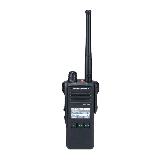
RADIO CONTROLS Top (Orange) Button MODEL 1 EMERGENCY Multi Function Control Knob (MFK)* Multi Function Control Knob (MFK)* Antenna Speaker Top Light bar TOP VIEW Menu Select Buttons... -
Page 4: Attaching/Removing The Battery
PREPARING YOUR RADIO FOR USE Attaching/Removing the Battery Slide the battery into the radio’s frame until the bottom latch To remove the battery, turn the radio off. Lift up the latch then clicks into place. slide the battery down to remove the battery from the radio. Battery Latch Battery Note: If your radio is preprogrammed with volatile-key... - Page 5 PREPARING YOUR RADIO FOR USE Antenna Note: Frequently check the antenna to ensure that it is tight. Antenna ONLY USE THE ANTENNA SUPPLIED WITH THE RADIO With the radio turned off, set the antenna in its receptacle and turn clockwise to attach it to the radio. To remove the antenna, turn the antenna counterclockwise.
- Page 6 PREPARING YOUR RADIO FOR USE Attaching/Removing the Accessory Connector Cover The accessory connector is located on the antenna side of the radio. It is used to connect accessories to the radio. Note: To prevent damage to the connector, shield it with the connector cover when not in use.
-
Page 7: Turning On/Off The Radio
PREPARING YOUR RADIO FOR USE Turning on/off the Radio Press the Control Knob until your radio display lights on, then release the knob. If the power-up test is successful, you see the Home screen. Note: If the power-up test is unsuccessful, you see Error XX/YY (XX/YY is an alphanumeric code). -
Page 8: Adjusting The Volume
PREPARING YOUR RADIO FOR USE Adjusting the Volume To increase the volume, rotate the MFK clockwise. Multi Function To decrease the volume, rotate the MFK counterclockwise. Control Knob (MFK)* The display shows volume bars and volume level when you change the volume. -
Page 9: General Operation
Butler Regional Interoperable Communications System GENERAL OPERATION APX 1000 Model 1... -
Page 10: Push-To-Talk (Ptt) Button
IDENTIFYING RADIO CONTROLS Push-To-Talk (PTT) Button The PTT button on the side of the radio serves two basic purposes: • While a call is in progress, the PTT button allows the radio to transmit to other radios in the call. Press and hold down PTT button to talk. - Page 11 MICROPHONES Speak Clearly into the microphone Red Lines indicate microphones...
-
Page 12: Accessing The Preprogrammed Functions
IDENTIFYING RADIO CONTROLS Accessing the Preprogrammed Functions You can access various radio functions through one of the following ways: • A short or long press of the relevant programmable buttons. • Use the Menu Select Buttons ( Using the Menu Select Buttons The Menu Select Buttons allow to access the menu entries of features. - Page 13 IDENTIFYING RADIO CONTROLS Multi Function Knob (MFK) MFK is the on/off button of your radio. In addition, there are programmable features available for MFK, which are: – Mode Change Turn MFK to scroll the channel or zone Multi Function list. Control Knob (MFK)* –...
-
Page 14: Emergency Operation
EMERGENCY Emergency Operation • You will be queried by a dispatch center about your activation. • EX: 9COM to 1S38, Are you declaring an emergency? Top (Orange) Button • If this is an actual emergent activation, simply EMERGENCY state your emergency and the resources needed. - Page 15 EMERGENCY Emergency Operation The Emergency feature is used to indicate a critical situation. Note: The radio operates in the normal dispatch manner while in Emergency Call, except if enabled, it returns to one If the Top (Orange) button is preprogrammed to send an of the following: emergency signal, this signal overrides any other •...
-
Page 16: Status Icons
IDENTIFYING STATUS INDICATORS Status Icons The 160 x 90 pixel front liquid crystal display (LCD) of the Direct • On = Radio is currently configured for direct radio shows radio status, text entries, and menu entries. radio-to-radio communication (during The top display row contain color icons that indicate radio conventional operation only). - Page 17 IDENTIFYING STATUS INDICATORS Scan User Login Indicator (IP Packet Data) • Radio is scanning a scan list. On = User is currently associated with the radio. • Off = User is currently not associated with the radio. • Blinking = Device registration or user registration with the server failed due to an invalid username or pin.
- Page 18 IDENTIFYING STATUS INDICATORS Top Light bar and LED Indicators The Top Light bar and LED indicators show the operational status of your radio. Top Light bar...
- Page 19 IDENTIFYING STATUS INDICATORS Top Light bar and LED Indicators – LED Indications – Solid red Radio is transmitting. – Blinking red Radio is transmitting at low battery condition. – Rapidly blinking red Radio has failed the self test upon powering up or encountered a fatal error. –...
- Page 20 IDENTIFYING STATUS INDICATORS Orange Green Emergency Alerts Critical Alerts Call Alerts...
-
Page 21: Intelligent Lighting Indicators
IDENTIFYING STATUS INDICATORS Intelligent Lighting Indicators This feature temporary changes the radio’s display backlight color and the alert text background color to help signal that a radio event has occurred. Note: This feature must be preprogrammed by a qualified radio technician. Backlight and Bar Color Notification When... -
Page 22: Alert Tones
IDENTIFYING STATUS INDICATORS Alert Tones Your radio uses alert tones to inform you of your radio’s condition. The following table lists these tones and when they occur. You Hear Tone Name Heard Short, Radio Self Test Fail When radio fails its power-up self test. Low-Pitched Reject When unauthorized request is made. - Page 23 IDENTIFYING STATUS INDICATORS You Hear Tone Name Heard Short, Valid Key-Press When correct key is pressed. Medium-Pitched Radio Self Test Pass When radio passes its power-up self test. Tone Clear Voice At beginning of a non-coded communication. Priority Channel Received When activity on a priority channel is received.
- Page 24 IDENTIFYING STATUS INDICATORS You Hear Tone Name Heard Two High-Pitched Tones GPS Fails When the GPS signal is lost or when GPS fails. Ringing Fast Ringing When system is searching for target of Private Call. Enhanced Call Sent When waiting for target of Private Call to answer the call. Phone Call Received When a land-to-mobile phone call is received.
-
Page 25: Selecting A Zone
GENERAL RADIO OPERATION Selecting a Zone Press the button with one dot (under the PTT) to move up a zone. Press the button with two dots (under the PTT) Zone Up to move down a zone. Zone Down... -
Page 26: Selecting A Radio Channel
GENERAL RADIO OPERATION Selecting a Radio Channel There are two ways to select a channel. Multi Function Procedure A: Control Knob (MFK)* Press the menu key “ChUp” or ChDn” to move up or down a channel. Procedure B: [MFK] Press the MFK down to enter Channel Change. -
Page 27: Receiving And Responding To A Radio Call
GENERAL RADIO OPERATION Receiving and Responding to a Radio Call Once you have selected the required channel and/or zone, you can proceed to receive and respond to calls. The LED lights up solid red while the radio is transmitting. In conventional mode, the LED lights up solid yellow when the radio is receiving a transmission. -
Page 28: Advanced Features
Butler Regional Interoperable Communications System ADVANCED FEATURES APX 1000 Model 1... - Page 29 ADVANCED FEATURES Scan Turning Scan On or Off This feature allows you to monitor traffic on different channels by scanning a preprogrammed list of channels. Procedure: [Preprogrammed Button] 1. Press the preprogrammed Scan button which is the purple button above the PTT Chan Scan Scan on / off SCAN...
-
Page 30: Scan Lists
ADVANCED FEATURES Scan Lists Viewing a Scan List Scan lists are created and assigned to individual channels/groups. Your radio scans for voice activity by cycling through the channel/group sequence specified in the scan list for the current channel/group. Procedure: 1. - Page 31 ADVANCED FEATURES Scan Lists Editing the Scan List This feature lets you change scan list members and priorities. Procedure: 1. Select the channel that you wish to add/remove to your scan list 3. Press the Menu Select button directly below ScnL 4.
- Page 32 SCANNING LE LE at Other PSAPs G LAW 3COM: Fairfield Name 4COM: Miami University 5COM: Trenton 09-3L MAIN 6COM: Monroe 09-4L MAIN 7COM: West Chester 09-5L MAIN 8COM: Middletown 9COM: Butler County 09-6L MAIN Zone G 09-7L MAIN •...
- Page 33 SCANNING FD FD at Other PSAPs 3COM: Fairfield F FIRE 4COM: Miami University Name 5COM: Trenton 09-3F MAIN 6COM: Monroe 09-5F MAIN 7COM: West Chester 09-6F MAIN 8COM: Middletown 09-7F MAIN 9COM: Butler County ...
- Page 34 9COM FIRE CHANNELS 09 ALPHA / “Nine Alpha” 09 BRAVO / “Nine Bravo” • Zone F (for scanning) • Zone F (for scanning) • 9COM fire / EMS • 9COM fire / EMS dispatching – West side dispatching for Hamilton departments FD, Liberty Twp FD and Fairfield Twp FD.
- Page 35 ADVANCED FEATURES Global Positioning System/ Global Navigation Satellite System The Global Navigation System (GNSS) in the radio integrated the information from the Global Positioning System (GPS) and Global Navigation Satellite System (GLONASS) to determine the approximate geographical location of your radio. Note: This feature is addressed as GPS across the manual as the naming convention of the buttons and strings remain the same as the legacy feature of GPS.
- Page 36 ADVANCED FEATURES Global Positioning System/ Global Navigation Satellite System GPS Operation The GPS technology uses radio signals from earth orbiting satellites, to establish the location coordinates, maximizing your view of clear unobstructed sky is essential for optimum performance. Where adequate signals from multiple satellites are not available (usually because you cannot establish a view of a wide area of the sky), the GPS feature of your radio will not work.
-
Page 37: Trunking System Controls
ADVANCED FEATURES Trunking System Controls Out-of-Range Radio When your radio goes out of the range of the system, it can no longer lock onto a control channel. Procedure: 1. You hear a low-pitched tone. AND/OR The display shows the currently selected zone/channel combination and Out of range. - Page 38 ADVANCED FEATURES Trunking System Controls Site Trunking Feature If the zone controller loses communication with any site, that site reverts to site trunking. The display shows the currently selected zone/channel combination and Site trunking. What does it mean when my radio says “SITE TRUNKING?”...
- Page 39 ADVANCED FEATURES Over-the-Air Programming (POP 25, ASTRO 25, ASTRO Conventional, and Wi-Fi) This feature enables configuration data and firmware to be upgraded to your radio over-the-air. Full use of the radio is retained during the data transfer without interrupting communication. For ASTRO 25 and ASTRO Conventional, the upgrade pauses to give priorities to voice call, and continues after the voice call ended.
- Page 40 ADVANCED FEATURES Over-the-Air Programming (POP 25, ASTRO 25, ASTRO Conventional, and Wi-Fi) Responding to the notification of Upgrade Procedure: 1. The display shows Upgrade?. Press the Menu Select button below Acpt to accept the request to upgrade immediately. The display shows Upg Rx In Prog to indicate the upgrade received is in progress. Press the Menu Select button below Dlay to delay the request to upgrade.
- Page 41 Butler Regional Interoperable Communications System UTILITIES APX 1000 Model 1...
-
Page 42: Time-Out Timer
UTILITIES Time-Out Timer This feature turns off your radio’s transmitter. You cannot transmit longer than the preset timer setting. If you attempt to do so, the radio automatically stops your transmission, and you hear a talk-prohibit tone. The timer is defaulted at 60 seconds. Note: You will hear a brief, low-pitched, warning tone four seconds before the transmission times out. - Page 43 Butler Regional Interoperable Communications System CHARGING AND MAINTENANCE APX 1000 Model 1...
- Page 44 CHARGING Motorola Impress® Smart Charger Recharge after each shift. This “smart” charger will: • Monitor usage patterns • Store that information in the battery • Recondition the battery when needed • Not overheat regardless of how long it’s left in...
- Page 45 CHARGING Charger Lights Charge Indicator Description Steady Battery is in rapid charge mode. Label Blinking Green Battery has completed rapid charge (>90% available capacity). on the Battery is in Top-Off charge (Trickle Charge) and requires bottom approximately 1 hour. of the Steady Green Battery has completed charging and is fully charged.
-
Page 46: Online Help
ONLINE HELP... -
Page 47: Radio Problems
TROUBLESHOOTING AND REPAIR Radio Problems If your radio is not working or broken, bring it to us! http://brics.butlersheriff.org/ 513-785-1299...