Advertisement
Quick Links
TABLE OF CONTENTS
1 Warning -------------------------------------------------------------- 2
2 Specifications ----------------------------------------------------- 2
3 Troubleshooting Guide ----------------------------------------- 3
4 Disassembly and Assembly Instructions ---------------- 7
5 Exploded View and Replacement Parts List -----------13
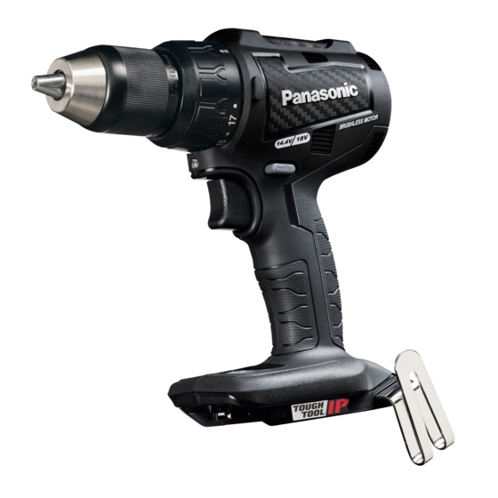
Cordless Hammer Drill & Driver
Model No.
Europe
PAGE
© Panasonic Corporation 2020. All rights reserved.
Unauthorized copying and distribution is a violation
of law.
ORDER NO. PTD2002E08CE
EY79A3
PAGE
Advertisement

Related Manuals for Panasonic EY79A3


Summary of Contents for Panasonic EY79A3
-
Page 1: Table Of Contents
2 Specifications ----------------------------------------------------- 2 3 Troubleshooting Guide ----------------------------------------- 3 4 Disassembly and Assembly Instructions ---------------- 7 5 Exploded View and Replacement Parts List -----------13 © Panasonic Corporation 2020. All rights reserved. Unauthorized copying and distribution is a violation of law. -
Page 2: Warning
1 Warning Caution: • Pb free solder has a higher melting point that standard solder; Typically the melting point is 50 - 70 °F (30 - 40 °C) higher. Please use a soldering iron with temperature control and adjust it to 750 ± 20 °F (400 ± 10 °C). In case of using high temperature soldering iron, please be careful not to heat too long. -
Page 3: Troubleshooting Guide
3 Troubleshooting Guide 3.1. Troubleshooting Guide... - Page 6 3.2. Trial Operation (after checking Troubleshooting Guide). 3.2.1. Assembly • Confirm if there is no gap between housing A, B and C by pinching lead wires. • There is no dust or deformation on battery terminals. 3.2.2. Operation • Check whether the tool operates properly in both the forward and reveres directions. •...
-
Page 7: Disassembly And Assembly Instructions
4 Disassembly and Assembly Instructions * To reduce the risk of injury, always remove battery pack before removing/installing the tool. * To assemble the tool, start with 4-9 and proceed to 4-1. 4.1. Removing the Plate Hook. 1. Remove the M4-14 screw. 2. - Page 8 4.3. Removing the Housing. 1. Remove nine screws. 2. Remove housing B. 3. Remove the F/R selector handle. 4. Remove the operation panel. 5. Remove the square nut. 4.4. Removing the Interior Components. 1. Remove the heat resistant tape and remove the interior components from the housing A.
- Page 9 4.5. Removing the Switch Assembly, LED Assembly and Battery Terminal. 1. Remove the 2-pin connector. 2. Remove the 6-pin connector. 3. Pull the faston terminal directly out from the switch assembly. * Exercise care not to bend the ter- minal fitting. 4.
- Page 10 4.7. Removing the Gear Box Block. 1. Rotate the motor mounting plate to the left and remove it from the gear case. * When installing the motor mounting plate to the gear case, align and engage the two protruded sec- tions on motor mounting plate with the two notches on the gear case, then turn the motor mounting plate clockwise until a clicking sound is produced to...
- Page 11 4.8. Assembly of the Gear Box Block and the Clutch Handle. 4.9. Assembly of the H/L Change Handle.
- Page 12 4.10. Wiring and Assembly Points.
-
Page 13: Exploded View And Replacement Parts List
5 Exploded View and Replacement Parts List Model No. : EY79A3 Exploded View... - Page 14 Model No. : EY79A3 Parts List Ref. Change Safety Part No. Part Name & Description Q'ty Remarks WEY79A3K3102 HOUSING AB SET WEY75A7H3247 F/R SELECTOR HANDLE WEY74A3L3202 OPERATION PLATE WEY7543K3187 PLATE HOOK WEY74A2H3237 H/L CHANGE HANDLE WEY6450L6806 CHUCK FASTENING SCREW WEY79A3L0101...