
Related Manuals for Cabletron Systems 6H122-16


Summary of Contents for Cabletron Systems 6H122-16
- Page 1 6H122-16 SmartSwitch 6000 Interface Module User’s Guide 9032361-03 FAST ENET 6H122-16 RESET 100 Mbs...
-
Page 3: Smartswitch
Only qualified personnel should install the 6H122-16. NOTICE Cabletron Systems reserves the right to make changes in specifications and other information contained in this document without prior notice. The reader should in all cases consult Cabletron Systems to determine whether any such changes have been made. -
Page 4: Industry Canada Notice
IMPORTANT: Before utilizing this product, carefully read this License Agreement. This document is an agreement between you, the end user, and Cabletron Systems, Inc. (“Cabletron”) that sets forth your rights and obligations with respect to the Cabletron software program (the “Program”) contained in this package. - Page 5 Government is subject to restrictions as set forth in subparagraph (c) (1) (ii) of the Rights in Technical Data and Computer Software clause at 252.227-7013. Cabletron Systems, Inc., 35 Industrial Way, Rochester, New Hampshire 03867-0505. 6H122-16 User’s Guide...
-
Page 6: Safety Information
Do not use optical instruments to view the laser output. The use of optical instruments to view laser output increases eye hazard. When viewing the output optical port, power must be removed from the network adapter. SAFETY INFORMATION SAFETY INFORMATION watts. 6H122-16 User’s Guide... -
Page 7: Declaration Of Conformity
Mr. Ronald Fotino ___________________________________ Full Name Principal Compliance Engineer ___________________________________ Title Rochester, NH, USA ___________________________________ Location 6H122-16 User’s Guide 89/336/EEC 73/23/EEC Cabletron Systems, Inc. 35 Industrial Way PO Box 5005 Rochester, NH 03867 Mr. J. Solari Cabletron Systems Limited Nexus House, Newbury Business Park... - Page 8 Notice 6H122-16 User’s Guide...
-
Page 9: Table Of Contents
10BASE-T Network ... 2-2 100BASE-TX Network ... 2-2 CHAPTER 3 INSTALLATION Unpacking the 6H122-16... 3-1 Installing the 6H122-16 into the 6C105 Chassis ... 3-2 Connecting to the Network ... 3-5 Completing the Installation ... 3-8 CHAPTER 4 TROUBLESHOOTING Using LANVIEW ... 4-1 Troubleshooting Checklist ... - Page 10 5.10 Chassis Environmental Screen ...5-29 5.11 Port Redirect Function Screen ...5-30 5.11.1 Changing Source and Destination Ports ...5-32 5.12 Module Selection Screen ...5-34 5.12.1 Selecting a Module...5-35 5.13 Module Menu Screen ...5-36 5.14 Module Configuration Menu Screen ...5-37 viii 6H122-16 User’s Guide...
- Page 11 5.23 Port Redirect Function Screen ... 5-79 5.23.1 Changing Source and Destination Ports... 5-81 5.24 Broadcast Suppression Screen ... 5-82 5.24.1 Setting the Threshold... 5-84 5.24.2 Setting the Reset Peak Switch ... 5-84 5.25 Module Statistics Menu Screen ... 5-85 6H122-16 User’s Guide Contents...
- Page 12 Device Specifications ... A-1 Physical Properties ... A-1 Environmental Requirements... A-1 Input/Output Ports... A-2 COM Port Pinout Assignments ... A-2 Regulatory Compliance... A-2 APPENDIX B MODE SWITCH BANK SETTINGS Required Tools... B-1 Setting the Mode Switch ... B-1 INDEX 6H122-16 User’s Guide...
-
Page 13: Chapter 1 Introduction
1, Introduction, outlines the contents of this manual, describes the features of the 6H122-16, and provides instructions for getting additional help. This chapter also includes a list of technology and user guides that may be helpful to set up and manage the 6H122-16. Chapter Network... -
Page 14: Overview
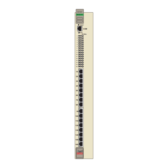
Cabletron Systems 6C105 chassis. The module provides sixteen RJ45 switched ports for unshielded twisted pair (UTP) cabling connectivity. The 6H122-16 is used to connect individual high-bandwidth user devices, such as workstations, and provide a central switching point for multiple 10/100 Mbps Fast Ethernet segments. -
Page 15: Reset Button
Reset Button COM Port System LED Port Status LEDs Network Ports 1-16 6H122-16 User’s Guide FAST ENET 6H122-16 RESET 100 Mbs Figure 1-1 The 6H122-16 Overview 2361_01... -
Page 16: Distributed Chassis Management
IP address. Its management functions are distributed to all modules. This means a single module in the chassis, such as the 6H122-16, can be used to manage the entire chassis, and any other attached module through Local Management, SNMP, or Telnet applications. -
Page 17: Smarttrunk
Distributed, resilient links increase reliability and performance. • Multiple technologies are supported within a single trunk for maximum flexibility. For more information about SmartTrunk, refer to the Cabletron Systems SmartTrunk User’s Guide. 1.3.8 Runtime IP Address Discovery This feature enables the modules to automatically accept an IP address from a BootP server on the network into NVRAM without requiring a user to enter an IP address through Local Management. -
Page 18: Port Redirect Function
100 Mbps when the device on the other end of the connection can also adjust between 10 Mbps or 100 Mbps. If the device on the other end of the connection can only operate at 10 Mbps, then the 6H122-16 adjusts to 10 Mbps operation. -
Page 19: Standards Compatibility
Chapter 4 provides details about the 6H122-16 LANVIEW LEDs. 1.3.14 Year 2000 Compliant The 6H122-16 module and 6C105 chassis have an internal clock that can maintain the time and date beyond the year 1999. 6H122-16 User’s Guide... -
Page 20: Document Conventions
Tip symbol. Conveys helpful hints concerning procedures or actions. Caution symbol. Contains information essential to avoid damage to the equipment. CAUTION Electrical Hazard Warning symbol. Warns against an action that could result in personal injury or death due to an electrical hazard. 6H122-16 User’s Guide... -
Page 21: Getting Help
Cabletron Systems Technical Writing Department via the following email address: TechWriting@cabletron.com Make sure to include the document Part Number in the email message. Before calling the Cabletron Systems Global Call Center, have the following information ready: • Your Cabletron Systems service contract number •... -
Page 22: Related Manuals
These manuals can be obtained from the World Wide Web in Adobe Acrobat Portable Document Format (PDF) at the following site: http://www.cabletron.com/ All documentation for the Cabletron Systems SecureFast VLAN NOTE Manager software is contained on the VLAN Manager CD-ROM. -
Page 23: Chapter 2 Network Requirements
Guide , can be found on the Cabletron Systems World Wide Web site: http://www.cabletron.com/ SmartTrunk To connect the 6H122-16 to a network so it can take advantage of the SmartTrunk feature, there are certain rules concerning port connections and configurations that must be followed for proper operation. Refer to the Cabletron Systems SmartTrunk User’s Guide for additional... -
Page 24: 10Base-T Network
Cabling Guide for details. 100BASE-TX NETWORK The sixteen fixed ports of the 6H122-16 provide an RJ45 connection that supports Category 5 unshielded twisted pair cabling with an impedance between 85 and 111 ohms. The device at the other end of the twisted pair segment must meet IEEE 802.3u 100BASE-TX Fast Ethernet network... -
Page 25: Chapter 3 Installation
6H122-16 Manual Accessory Kit Before proceeding with the installation, visually inspect the NOTE module for damage. If the module appears to be damaged, contact the Cabletron Systems Global Call Center. Refer to Section 1.5 6H122-16 User’s Guide CHAPTER 3 INSTALLATION (Section 3.1) -
Page 26: Installing The 6H122-16 Into The 6C105 Chassis
Damage could result from sharp objects contacting the board CAUTION or components. The 6H122-16 can be installed in any of the 5 slots that are available. To install a module, proceed as follows: Remove the blank panel covering the slot in which the module will be installed. - Page 27 When installing a module, ensure that the top plastic locking NOTE tab lines up with the desired slot number located on the front panel of the chassis. Refer to 6H122-16 User’s Guide Installing the 6H122-16 into the 6C105 Chassis Figure Figure 3-1. 3-1.
- Page 28 Chapter 3: Installation Metal Back-Panel Figure 3-1 Installing an Interface Module Slot Number Backplane Connector FAST ENET 6E122-16 RESET 100 Mbs 100 Mbs Circuit Card Card Guides Plastic Locking Tab 2159-01 Plastic Locking Tab 2361-02 6H122-16 User’s Guide...
-
Page 29: Connecting To The Network
Cabletron Systems SmartTrunk User’s Guide for the configuration information. Ports 1 through 16 of the 6H122-16 are 10/100 ports with internal crossovers. The ports have RJ45 connectors for twisted pair connections. When connecting a workstation, use a straight-through cable. When connecting networking devices, such as another bridge, repeater, or router, use a crossover cable. - Page 30 Chapter 3: Installation Figure 3-2 6H122-16 Twisted Pair Connection Verify that a link exists by checking that the port RX LED is ON (flashing amber, blinking green, or solid green). If the RX LED is OFF and the TX LED is not blinking amber, perform the following steps...
- Page 31 Cabletron Systems Cabling Guide. Refer to document. If a link is not established, contact the Cabletron Systems Global Call Center. Refer to Section 1.5 Repeat steps 1 through 3 above, until all connections have been made.
-
Page 32: Completing The Installation
Chapter 3: Installation COMPLETING THE INSTALLATION After installing the 6H122-16, the module is now ready to be set up through Local Management. Refer to Chapter 5 to configure the module and 6C105 chassis. 6H122-16 User’s Guide... -
Page 33: Chapter 4 Troubleshooting
Troubleshooting network and module operational problems • Using the RESET button USING LANVIEW The 6H122-16 uses Cabletron Systems built-in visual diagnostic and status monitoring system called LANVIEW. The LANVIEW LEDs (Figure 4-1) allow quick observation of the network status to aid in the diagnosing of network problems. - Page 34 Chapter 4: Troubleshooting CPU LED Receive (RX) Transmit (TX) FAST ENET 6H122-16 RESET 100 Mbs Figure 4-1 LANVIEW LEDs 10/100 Mbps Operation 2361_07 6H122-16 User’s Guide...
- Page 35 Color Amber Green Amber Green Green Amber 6H122-16 User’s Guide Table 4-1 LANVIEW LEDs State Power off. Blinking. Hardware failure has occurred. Solid. Resetting, normal power up reset. Blinking. Crippled. Solid. Testing. Solid. Functional. Booting. Blinks amber and green while booting.
- Page 36 3. If still not working, contact the Cabletron Systems Global Call Center. None, unless a high amount of activity. Check for network configuration problems or bad device. Contact Cabletron Systems Global Call Center. 6H122-16 User’s Guide...
-
Page 37: Troubleshooting Checklist
TROUBLESHOOTING CHECKLIST If the 6H122-16 is not working properly, refer to of possible problems, causes, and recommended actions to resolve the problem. Table 4-3 Troubleshooting Checklist Problem Possible Cause All LEDs are OFF. Loss of Power to the 6C105 chassis. - Page 38 Chapter 4: Troubleshooting Table 4-3 Troubleshooting Checklist (Continued) Problem Possible Cause Port(s) goes into The 6H122-16 detects a standby for no looped condition. apparent reason. User parameters Mode switch (7), NVRAM (IP address, Reset, was changed Device and sometime before either...
-
Page 39: Using The Reset Button
Reset Button To reset the 6H122-16 processor, press and release the RESET button. The module processor goes through a reset process of approximately 20 seconds. Additional downtime may be added as the module reenters the network. - Page 40 Chapter 4: Troubleshooting 6H122-16 User’s Guide...
-
Page 41: Chapter 5 Local Management
LOCAL MANAGEMENT This chapter explains how to set up a management terminal to access 6H122-16 Local Management. It also explains how to use the Local Management screens and commands. OVERVIEW Local Management for the 6H122-16 consists of a series of management screens that allows management of the module, the attached segments, and the 6C105 chassis. -
Page 42: Local Management Keyboard Conventions
Management increment field. For example, “Press [–]” means to press the minus sign key. The DEL (Delete) key removes characters from a Local Management field. For example, “Press DEL” means to press the Delete key. Table 5-1 explains 6H122-16 User’s Guide... -
Page 43: Management Terminal Setup
6H122-16 as follows: Connect the RJ45 connector at one end of the cable (supplied in the kit) to the COM port on the 6H122-16. Plug the RJ45 connector at the other end of the cable into the RJ45-to-DB9 adapter (supplied in the kit). - Page 44 Chapter 5: Local Management RJ45 COM Port RJ45 Connectors PC Adapter to PC Figure 5-1 Management Terminal Connection ETHERNET 6E122-16 RESET 100 Mbs UTP Cable with RJ45-to-DB9 FAST ENET 6H122-16 RESET 100 Mbs 2361_10 6H122-16 User’s Guide...
-
Page 45: Management Terminal Setup Parameters
Auto Answerback -> Keyboard Setup Menu Keys -> Auto Repeat -> Keyclick -> Margin Bell -> Warning Bell -> 6H122-16 User’s Guide Management Terminal Setup Table 5-2 VT Terminal Setup 80 Columns Interpret Controls No Auto Wrap Jump Scroll Cursor... -
Page 46: Telnet Connections
Use the Console Cable Kit provided with the 6C105 chassis to attach the UPS to the module COM port as shown in Connect the UPS device to the COM port of the 6H122-16 as follows: Connect the RJ45 connector at one end of the cable to the COM port on the 6H122-16. - Page 47 RJ45 COM Port UTP Cable with RJ45 Connectors RJ45-to-DB9 PC Adapter Figure 5-2 Uninterruptible Power Supply (UPS) Connection 6H122-16 User’s Guide Management Terminal Setup ETHERNET 6E122-16 RESET 100 Mbs DB9 Port FAST ENET 6H122-16 RESET 100 Mbs UPS Device 2361_11...
-
Page 48: Accessing Local Management
Local Management. Turn on the terminal. Press ENTER (this may take up to four times, because the COM port of the 6H122-16 auto-senses the baud rate of the terminal) until the 6C105 Local Management Password screen, Figure 5-3, displays. -
Page 49: Navigating Local Management Screens
5.4.1 Navigating Local Management Screens The 6H122-16 Local Management application consists of a series of menu screens. Navigate through Local Management by selecting items from the menu screens. The 6H122-16 supports three modes of switch operation. The switching modes are as follows: •... - Page 50 Ethernet Interface Configuration SmartTrunk Configuration Module Specific Configuration Switch Statistics Module Interface Statistics Statistics RMON Statistics Menu Network Tools System Resources Flash Download Port Redirect Function Broadcast Suppression 2361_100 System Resources Flash Download Broadcast Suppression 802.1Q VLAN Configuration 2361_101 6H122-16 User’s Guide...
-
Page 51: Selecting Local Management Menu Screen Items
Use the arrow keys to highlight the EXIT command at the bottom of the Local Management screen. Press ENTER. The Chassis Main Menu screen displays and the session ends. 6H122-16 User’s Guide Accessing Local Management Chassis Configuration SNMP Community Names... - Page 52 ESC twice. This exit method does not warn about unsaved changes and all unsaved changes will be lost. Exit from 6H122-16 Local Management by repeating steps 1 and 2 until the chassis Main Menu screen displays. Use the arrow keys to highlight the RETURN command at the bottom of the chassis Main Menu screen.
-
Page 53: The Main Menu Screen
The Modules menu item provides access to the Module Selection screen that is used to select individual modules in the chassis for management purposes. For details about the Module Selection screen, refer to Section 5.12. 6H122-16 User’s Guide 6C105 LOCAL MANAGEMENT Main Menu CHASSIS MODULES... -
Page 54: Chassis Menu Screen
6C105 chassis. For details, refer to 5-14 Figure 5-8, provides access to Local 6C105 LOCAL MANAGEMENT Chassis Menu CHASSIS CONFIGURATION SNMP COMMUNITY NAMES SNMP TRAPS CHASSIS ENVIRONMENTAL PORT REDIRECT FUNCTION EXIT RETURN 2361_99a Section 5.7. 6H122-16 User’s Guide... - Page 55 PORT REDIRECT FUNCTION The Port Redirect Function screen allows the user to redirect traffic from one or multiple modules and ports in the chassis to a specific destination module or port. For details, refer to Section 5.11. 6H122-16 User’s Guide 5-15...
-
Page 56: Chassis Configuration Screen
5-9, displays. 6C105 LOCAL MANAGEMENT Chassis Configuration 00-00-ID-00-00-00 0.0.0.0 0.0.0.0 EXIT 5.7.1. Chassis Date: 01/11/1998 Chassis Time: 14:23:00 Screen Refresh Time: 30 sec. Screen Lockout Time: 15 min. Chassis Uptime XX D XX H XX M RETURN 6H122-16 User’s Guide 2361_41... - Page 57 Management screens. In this example, after five minutes of “idleness” (no input or action), the terminal “beeps” five times, the Local Management application terminates the session, and the display returns to the Password screen. To enter a new lockout time, refer to 6H122-16 User’s Guide Chassis Configuration Screen Section 5.7.3.
-
Page 58: Setting The Ip Address
In 802.1D SWITCHING mode, the 16 ports located on the front panel are bridged to each other. When the operational mode is set to 802.1Q SWITCHING, the 6H122-16 acts as an IEEE 802.1Q switch. The module can be configured to increase its switching functionality by creating and maintaining port based Virtual LANs (VLANs). -
Page 59: Setting The Subnet Mask
Enter the date in this format: MM/DD/YYYY It is not necessary to add separators between month, day, and NOTE year numbers. For example, to set the date to 01/17/1998, type “01171998” in the Chassis Date field. 6H122-16 User’s Guide Chassis Configuration Screen 5-19... -
Page 60: Setting The Chassis Time
Management does not alter the current value and refreshes the Chassis Time field with the previous value. Upon saving the new chassis time, all interface modules NOTE installed in the chassis recognize the new value as the current time. 5-20 ., type “064500” in the 6H122-16 User’s Guide... -
Page 61: Entering A New Screen Refresh Time
Line at the top of the screen displays “SAVED OK”. If the entry is not valid, the Event Message Line displays “PERMISSIBLE RANGE: 1...30” momentarily. Local Management does not alter the current setting, but it does refresh the Screen Lockout Time field with the previous value. 6H122-16 User’s Guide Chassis Configuration Screen 5-21... -
Page 62: Setting The Operational Mode
ARE YOU SURE YOU WANT TO SAVE THE NEW OPERATIONAL MODE? Figure 5-10 Operational Mode Warning Screen Use the arrow keys to highlight the YES command and press ENTER. The changes are saved, and all the modules installed in the chassis reboot. 5-22 WARNING! 6H122-16 User’s Guide 1666_1... - Page 63 Chassis Configuration Screen If the 6H122-16 has been set to 802.1Q SWITCHING, refer to NOTE your Port Based VLAN User’s Guide to configure the devices for this type of operation. The Operational Mode field in the Chassis Configuration screen does not support the SECURE FAST VLAN operational mode.
-
Page 64: Snmp Community Names Screen
NAMES menu item and press ENTER. The SNMP Community Names screen, Figure 5-11, displays. Event Message Line Community Name public public public SAVE Figure 5-11 SNMP Community Names Screen 5-24 6C105 LOCAL MANAGEMENT SNMP Community Names Access Policy read-only read-write super-user EXIT RETURN 2361_35 6H122-16 User’s Guide... -
Page 65: Establishing Community Names
Local Management. The community name assigned Super-User access is the only one that gives the user complete access to Local Management. 6H122-16 User’s Guide SNMP Community Names Screen This community name allows read-only access to the 6C105 MIB objects, and excludes access to security-protected fields of read-write or... -
Page 66: Snmp Traps Screen
The SNMP Traps screen is shown in To access the SNMP Traps screen from the Chassis Menu screen, use the arrow keys to highlight the SNMP TRAPS menu item and press ENTER. The Chassis SNMP Traps screen displays. 5-26 Section 5.16. Figure 5-12. 6H122-16 User’s Guide... - Page 67 Network Management Station with the associated IP address. Enable Traps (Toggle) Enables transmission of the traps to the network management station with the associated IP address. This field toggles between YES and NO. 6H122-16 User’s Guide 6C105 LOCAL MANAGEMENT Chassis SNMP Traps Trap Community Name...
-
Page 68: Configuring The Trap Table
ENTER. The message “SAVED OK” displays on the screen. Exiting without saving causes a “NOT SAVED?” message to NOTE appear. Edits will be lost if they are not saved before exiting. The designated workstations now receive traps from the 6C105. 5-28 6H122-16 User’s Guide... -
Page 69: Chassis Environmental Screen
Displays the current status of power supplies 1 and 2 for the 6C105. This field will read either “Normal” (power redundancy is operating properly), “Fault” (power supply is defective), or “Not Installed” (no power supply in that slot). 6H122-16 User’s Guide Chassis Environmental Screen Figure 5-13, displays. -
Page 70: Port Redirect Function Screen
Operating a chassis without a fan tray installed may cause the chassis or installed modules to overheat and become a fire CAUTION hazard. Cabletron Systems does not recommend operation of a chassis without a fully functioning fan tray unit. 5.11... - Page 71 Displays which ports are currently set as source ports. Destination Module (Read-Only) Displays which modules are currently set as destination modules. Destination Port (Read-Only) Displays which ports are currently set as destination ports. 6H122-16 User’s Guide Port Redirect Function Screen 6C105 LOCAL MANAGEMENT Port Redirect Function Destination...
-
Page 72: Changing Source And Destination Ports
Use the arrow keys to highlight the Source Module field. Press the SPACE bar or BACKSPACE one or more times to increment or decrement the module number displayed in the brackets [n] until the appropriate module number is displayed. 5-32 6H122-16 User’s Guide... - Page 73 1 through 12 for each additional setting, then go to step 13 to save all the new settings at once. Use the arrow keys to highlight SAVE at the bottom of the screen. Press ENTER. The message “SAVED OK” is displayed. 6H122-16 User’s Guide Port Redirect Function Screen 5-33...
-
Page 74: Module Selection Screen
< > characters indicates the module to which the management terminal or Telnet session is connected. 5-34 6C105 LOCAL MANAGEMENT Module Selection MODULE Name Serial # 6H122-16 123456789 6E132-25 123456789 6E123-26 123456789 6E122-26 123456789 EXIT Figure 5-15 Hardware Revision RETURN 2361_39 6H122-16 User’s Guide... -
Page 75: Selecting A Module
Serial # (Read-only) Indicates the serial number of the module. The serial number is necessary when calling the Cabletron Systems Global Call Center concerning an issue with the device. Hardware Revision (Read-only) Reflects the hardware version of the module. -
Page 76: Module Menu Screen
MODULE CONFIGURATION The Module Configuration screen provides access to the Local Management screens that are used to configure the 6H122-16 and also provides access to the Module Specific Configuration menu screen. This screen provides access to the screens that allow the user to check the 6H122-16 resources and set operating parameters specific to each port. -
Page 77: Module Configuration Menu Screen
6H122-16. For details about this screen, refer to Section 5.25. NETWORK TOOLS The Network Tools function resides on the 6H122-16 and consists of a series of commands that allow the user to access and manage network devices. Section 5.29 5.14... - Page 78 The following briefly explains each screen accessible from the Module Configuration Menu screen: GENERAL CONFIGURATION The General Configuration screen allows the user to monitor and configure operating parameters for the 6H122-16. For details, refer to Section 5.15. SNMP COMMUNITY NAMES...
- Page 79 Refer to the Cabletron Systems SmartTrunk User’s Guide for additional information. MODULE SPECIFIC CONFIGURATION The Module Specific Configuration Menu screen allows the user to configure ports or check system resources specific to the 6H122-16. For details, refer to Section 5.20.
-
Page 80: General Configuration Screen
To access the General Configuration screen from the Module Configuration Menu screen, use the arrow keys to highlight the GENERAL CONFIGURATION menu item and press ENTER. The General Configuration screen displays. Event Message Line Module Type: 6H122-16 Slot Number: X MAC Address: IP Address: Subnet Mask:... - Page 81 IP Address (Modifiable) This field allows the IP address to be set for the 6H122-16. To set the IP address, refer to Section The IP Address can also be set through Runtime IP Address NOTE Discovery as previously described in Subnet Mask (Modifiable)
- Page 82 Displays the total time that the module has been operating. Operational Mode (Selectable) This field sets the 6H122-16 to operate as an IEEE 802.1D switch (802.1D SWITCHING option), an IEEE 802.1Q switch (802.1Q SWITCHING option), or as a Cabletron Systems SecureFast switch (SECURE FAST VLAN option).
- Page 83 Clear NVRAM (Toggle) This allows the user to reset NVRAM to the factory default settings. All user-entered parameters, such as IP address and Community Names are then replaced with 6H122-16 default configuration settings. For details, refer to Section 5.15.13.
-
Page 84: Setting The Ip Address
IP Fragmentation (Toggle) This field allows the user to enable or disable IP fragmentation. The default setting for this field is ENABLED. If the 6H122-16 will be bridged to an FDDI ring, IP Fragmentation should be enabled. If IP Fragmentation is disabled, all FDDI frames that exceed the maximum Ethernet frame size will be discarded. -
Page 85: Setting The Subnet Mask
5.15.2 Setting the Subnet Mask If the management workstation that is to receive SNMP traps from the 6H122-16 is located on a separate subnet, the subnet mask for the 6H122-16 must be changed from its default. To change the subnet mask from its default, perform the following steps: Use the arrow keys to highlight the Subnet Mask field. -
Page 86: Setting The Default Gateway
If the SNMP management station is located on a different IP subnet than the 6H122-16, a default gateway must be specified. When an SNMP Trap is generated, the 6H122-16 sends the Trap to the default gateway. To set the default gateway, perform the following steps: Use the arrow keys to highlight the Default Gateway field. -
Page 87: Setting The Tftp Gateway Ip Address
5.15.4 Setting the TFTP Gateway IP Address If the network TFTP server is located on a different IP subnet than the 6H122-16, a Gateway IP address should be specified. To set the TFTP Gateway IP address, perform the following steps: Use the arrow keys to highlight the TFTP Gateway IP Address field. -
Page 88: Setting The Module Time
If the 6C105 chassis has been assigned a chassis time, it is not NOTE necessary to assign a module time to the 6H122-16. All installed modules recognize the chassis time of the 6C105. Use the arrow keys to highlight the Module Time field. -
Page 89: Entering A New Screen Refresh Time
Line at the top of the screen displays “SAVED OK”. If the entry is not valid, the Event Message Line displays “PERMISSIBLE RANGE: 1...30” momentarily. Local Management does not alter the current setting, but it does refresh the Screen Lockout Time field with the previous value. 6H122-16 User’s Guide General Configuration Screen 5-49... -
Page 90: Setting The Operational Mode
The module must be assigned a unique IP address. If the module will be a SecureFast switch, distributed management is not allowed. The Management Mode of the module will automatically be set to STANDALONE. The Management Mode field will no longer display on the General... - Page 91 Port Based VLAN User’s Guide to configure the module for this type of operation. If the 6H122-16 has been set to SECURE FAST VLAN, refer to your SecureFast documentation set to configure the module for this type of operation.
-
Page 92: Setting The Management Mode
ARE YOU SURE YOU WANT TO CONTINUE? Figure 5-22 Configuration Warning Screen Use the arrow keys to highlight the YES command and press ENTER. The changes are saved and the module reboots. 5-52 Figure 5-22 WARNING! (Section 5.16). displays. 174252 6H122-16 User’s Guide... -
Page 93: Configuring The Com Port
COM port configuration section before changing the settings of the COM port. The 6H122-16 COM port supports the following applications: Refer to the Release Notes included with the 6H122-16 to NOTE verify which COM Port applications are currently supported. •... - Page 94 OK” displays, the edits are saved. Exiting without saving causes the message “NOT SAVED -- PRESS SAVE TO KEEP CHANGES” to appear. Exiting without saving causes all edits to be lost. CAUTION 5-54 WARNING! Section 5.15.12. If you 6H122-16 User’s Guide 174252...
-
Page 95: Changing The Com Port Application
COM port application. If the module does not have a valid IP address and the changes are saved, refer to Appendix B reestablish COM port communications. 6H122-16 User’s Guide General Configuration Screen Application Local Management Session APC Power Supply SNMP Proxy... -
Page 96: Clearing Nvram
Figure 5-24 Clear NVRAM Warning Screen To clear NVRAM, use the arrow keys to highlight YES and press ENTER. The message “CLEARING NVRAM. REBOOT IN PROGRESS...” displays. The 6H122-16 clears NVRAM and reboots. All user-entered parameters default to factory settings. 5-56 Figure 5-24 WARNING! 6H122-16 User’s Guide... -
Page 97: Enabling/Disabling Ip Fragmentation
Local/Remote Management community names. Community names act as passwords to Local/Remote Management and are agents of security access to the 6H122-16. Access to the 6H122-16 is controlled by invoking any of three different levels of security authorization (read-only, read-write, and super-user). - Page 98 Figure 5-25 SNMP Community Names Screen The following explains each SNMP Community Names screen field: Community Name (Modifiable) Displays the user-defined name through which a user accesses 6H122-16 management. Any community name assigned here acts as a password to Local/Remote Management.
-
Page 99: Establishing Community Names
6H122-16 User’s Guide SNMP Community Names Screen This community name permits read-write access to the 6H122-16 MIB objects and allows the user to change all modifiable parameters including community names, IP addresses, traps, and SNMP objects. -
Page 100: Snmp Traps Screen
Chapter 5: Local Management 5.17 SNMP TRAPS SCREEN Since the 6H122-16 is an SNMP compliant device, it can send messages to multiple Network Management Stations to alert users of status changes. The SNMP Traps screen is shown in It is only necessary to assign SNMP traps if the user desires... -
Page 101: Configuring The Trap Table
NO (prevent alarms from being sent). Using the arrow keys, highlight the SAVE command and press ENTER. The message “SAVED OK” displays on the screen. The designated workstations now receive traps from the 6H122-16. 6H122-16 User’s Guide SNMP Traps Screen... -
Page 102: Switch Configuration Screen
FAST VLAN. This screen may only be used by modules configured to operate as 802.1D or 802.1Q switches. To access the Switch Configuration screen from the Module Configuration Menu screen, use the arrow keys to highlight the SWITCH CONFIGURATION menu item and press ENTER. The Switch Configuration screen, edit the fields for ports 9 to 16, highlight the navigation field [9-16] at the... - Page 103 DEC, and NONE. To set the STA, refer to Age Time (Modifiable) Allows the user to set the amount of time (in seconds) the 6H122-16 will keep an address in its switch table before discarding it. The module will discard an address from its switch table if it does not receive a valid frame from the applicable address in the amount of time specified in the Age...
-
Page 104: Setting The Sta
When the specific Navigation field is available, it allows the user to view the Switch Configuration for ports 1 through 8, ports 9 through 16, or ports 17 through 21. Once this field is highlighted, press the ENTER key to go to the desired screen. -
Page 105: Setting The Age Time
Use the SPACE bar to toggle to either ENABLED or DISABLED. Use the arrow keys to highlight the SAVE command at the bottom of the screen. Press ENTER. The message “SAVED OK” is displayed. 6H122-16 User’s Guide Switch Configuration Screen 5-65... -
Page 106: Ethernet Interface Configuration
FE-100TX No Link Flow Control Admin Status: SAVE Figure 5-28 Ethernet Interface Configuration Screen for the 6H122-16 All ports are capable of 10 or 100 Mbps operation, however NOTE only ports 15 and 16 support Full Duplex Switched Ethernet (FDSE) for 100 Mbps. - Page 107 NOTE a link with the device at the other end of the segment without requiring user setup. However, Local Management provides the user with the option of manually configuring that port. 6H122-16 User’s Guide Ethernet Interface Configuration Section 5.19.2. 5-67...
-
Page 108: Configuring The Ports
Section 5.19.4 5.19.1 Configuring the Ports In normal operation, a 6H122-16 interface automatically establishes a link with the device at the other end of the segment and no user setup is required. Section 5.19.2 manually configuring the interface. -
Page 109: Setting The Advertised Ability
ENTER. Use the arrow keys to highlight the SAVE command. Press ENTER. The message “SAVED OK” displays and Local Management saves the changes to memory. The selected mode is displayed in the field. 6H122-16 User’s Guide Ethernet Interface Configuration 5-69... -
Page 110: Module Specific Configuration Menu Screen
SCREEN The Module Specific Configuration menu screen, user to select one of up to five screens to configure ports or check system resources specific to the 6H122-16. The BROADCAST SUPPRESSION menu item on the Module NOTE Specific Configuration menu screen may not display if the operational mode of the module has been set to SECURE FAST VLAN. -
Page 111: System Resources
SYSTEM RESOURCES The System Resources screen displays the amount of FLASH memory, DRAM, and NVRAM installed, details how much memory is available and provides information on 6H122-16 operation. For details, refer to Section 5.21. 6H122-16 User’s Guide Module Specific Configuration Menu Screen... -
Page 112: System Resources Screen
Chapter 5: Local Management FLASH DOWNLOAD The FLASH Download screen allows the user to force the 6H122-16 to download a new image file to FLASH memory from a TFTP server. For details, refer to Section 5.22. PORT REDIRECT FUNCTION The Port Redirect Function screen allows the user to redirect traffic from one or more ports on the module to a specific destination port on the... - Page 113 Indicates the amount of FLASH memory installed in the 6H122-16 and how much is currently available. DRAM Installed (Read-only) Indicates the amount of DRAM installed in the 6H122-16 and how much of it is currently available. NVRAM Installed (Read-only) Indicates the amount of NVRAM installed in the 6H122-16 and how much of it is currently available.
-
Page 114: Setting The Reset Peak Utilization
Chapter 5: Local Management Current Switch Utilization (Read-only) Shows how much (percentage of capacity) the 6H122-16 is currently being used. Peak Switch Utilization (Read-only) Shows the peak percentage of maximum switching capacity, since last reset. Reset Peak Switch Utilization (Toggle) Allows the user to reset the Peak Switch Utilization field. - Page 115 TFTP server and the filename of the image to be downloaded. If set for TFTP or RUNTIME, the 6H122-16 attempts a TFTP download based on the IP address and filename entered in the fields at the bottom of the Flash Download screen.
-
Page 116: Image File Download Using Tftp
BootP. Reboot After Download (Modifiable when RUNTIME is chosen only) This field notifies the user that the 6H122-16 will reboot after the download is complete. If a RUNTIME Download is performed, this field toggles between YES and NO. If YES is selected, the module reboots after the download is completed. -
Page 117: Image File Download Using Runtime
FLASH memory. 5.22.2 Image File Download Using RUNTIME Set the 6H122-16 to download to FLASH using RUNTIME as follows: Use the arrow keys to highlight the Download Method field. Use the SPACE bar to select RUNTIME. -
Page 118: Image File Download Using Bootp
FLASH memory. 5.22.3 Image File Download Using BootP Set the 6H122-16 to download to FLASH using BootP as follows: Use the arrow keys to highlight the Download Method field. Use the SPACE bar to select BOOTP. -
Page 119: Port Redirect Function Screen
The Port Redirect Function screen, each one of the ports on the 6H122-16 as a source or destination port. A port can be set to have one or more destination ports. For example, port 1 can be set as a source port with three destinations, ports 2, 3, and 4. - Page 120 Chapter 5: Local Management Event Message Line Module Type: 6H122-16 Slot Number: X Source Port ------------------ Source Port [1] SAVE Figure 5-32 Port Redirect Function Screen The following definitions briefly explain each field of the Port Redirect Function screen: Source Port (Read-only) Shows which ports are currently set as source ports.
-
Page 121: Changing Source And Destination Ports
Use the SPACE bar to select either the ON or OFF option and press ENTER. ON forces the source module and port to forward errored frames to the destination module(s) and port(s). OFF forces the errored frames to be dropped before forwarding traffic. 6H122-16 User’s Guide Port Redirect Function Screen 5-81... -
Page 122: Broadcast Suppression Screen
To access the Broadcast Suppression screen from the Module Specific Configuration screen, use the arrow keys to highlight the BROADCAST SUPPRESSION menu item and press ENTER. The Broadcast Suppression screen displays. 5-82 Figure 5-33, allows the user to set a for instructions on configuring the operational 6H122-16 User’s Guide... - Page 123 Event Message Line Module Type: 6H122-16 Slot Number: X PORT # Total RX 12345678910 12345678910 12345678910 12345678910 12345678910 12345678910 12345678910 12345678910 12345678910 12345678910 12345678910 12345678910 SAVE Figure 5-33 Broadcast Suppression Screen The following explains each field of the Broadcast Statistics screen: PORT # (Read-only) Identifies the number of the port.
-
Page 124: Setting The Threshold
Press ENTER. The message “SAVED OK” is displayed. 5.24.2 Setting the Reset Peak Switch To reset the Reset Peak Switch counter to zero, proceed as follows: Use the arrow keys to highlight the Reset Peak field for the selected port. -
Page 125: Module Statistics Menu Screen
MODULE STATISTICS MENU SCREEN The Module Statistics Menu screen, screens that allow the user to obtain switch statistics about frame traffic through each interface, to view MIB-II statistics from each interface, and to view RMON Statistics gathered by the RMON agent embedded in the 6H122-16. - Page 126 The Interface Statistics screen provides the MIB-II statistics for each switched interface, on an interface-by-interface basis. RMON STATISTICS The RMON Statistics screen displays all the statistics gathered by the embedded RMON agent built-in to the 6H122-16. 5-86 6C105 LOCAL MANAGEMENT Module Statistics Menu Firmware Revision: BOOTPROM Revision: XX.XX.XX...
-
Page 127: Switch Statistics Screen
802.1D or 802.1Q switches. Ports 17 through 20 represent the backplane connections that the 6H122-16 has with the 6C105 chassis. The module has a direct connection to every other slot in the chassis. To access the Switch Statistics screen from the Module Statistics Menu screen, use the arrow keys to highlight the SWITCH STATISTICS menu item and press ENTER. -
Page 128: Using The Clear Counters Command
field, refer to NEXT/PREVIOUS (Navigation Field) The first time the Switch Statistics screen comes up, there is a NEXT field that the user can arrow key over and highlight. Pressing the ENTER key displays the next screen. In the new screen, the navigation field PREVIOUS will display to allow the user to go back to the first screen. -
Page 129: Interface Statistics Screen
INTERFACE STATISTICS SCREEN The Interface Statistics screen is used to gather MIB-II statistics for all of the 6H122-16 interfaces (ports 1 through 16 and all backplane interfaces). To access the Interface Statistics screen, use the arrow keys to highlight the INTERFACE STATISTICS menu item on the Module Statistics Menu screen and press ENTER. - Page 130 The InDiscards field displays the total number of inbound frames that were discarded, even though the frames contained no errors. This field may increment because the switch needed to free up buffer space, or the switch was being overutilized. InErrors (Read-only) This field displays the total number of inbound frames that have been...
- Page 131 The OutDiscards field displays the total number of outbound frames that were discarded, even though the frames contained no errors. This field may increment because the switch needed to free up buffer space, or because the switch was being overutilized.
-
Page 132: Displaying Interface Statistics
To reset all the statistics counters of the selected interface to zero, perform the following steps: Use the arrow keys to highlight the CLEAR COUNTERS command. Press ENTER, the counters for the selected interface are reset to zero. 5-92 Section 5.27.2. 6H122-16 User’s Guide Section 5.27.1. -
Page 133: Rmon Statistics Screen
The following definitions explain each field of the RMON Statistics screen: RMON Index (Read-only) This field displays the current Ethernet interface for which statistics are being shown. The 6H122-16 has an embedded RMON agent that gathers statistics for each interface on the module. 6H122-16 User’s Guide RMON Statistics Screen... - Page 134 Drop Events (Read-only) This field displays the total number of times that the RMON agent was forced to discard frames due to the lack of available switch resources. The Drop Events field does not display the actual number of NOTE frames dropped, it only displays the number of times that the RMON agent was forced to discard frames.
- Page 135 64 bytes in length (excluding framing bits, but including CRC bytes). 65 - 127 Octets (Read-only) Displays the total number of frames, including bad frames, received that were between 65 and 127 bytes in length (excluding framing bits, but including CRC bytes). 6H122-16 User’s Guide RMON Statistics Screen 5-95...
- Page 136 Section 5.28.1. CLEAR COUNTERS (Command) This command is used to reset all statistic counters to zero. For details on how to use this field, refer to Section 5.28.2. 5-96 6H122-16 User’s Guide...
-
Page 137: Displaying Rmon Statistics
To reset all the statistics counters of the selected interface to zero, perform the following steps: Use the arrow keys to highlight the CLEAR COUNTERS field. Press ENTER, the counters for the selected index are reset to zero. 6H122-16 User’s Guide RMON Statistics Screen 5-97... -
Page 138: Network Tools
Chapter 5: Local Management 5.29 NETWORK TOOLS The Network Tools function resides on the 6H122-16 and allows the user to access and manage network devices. To access the Network Tools screen, use the arrow keys to highlight the NETWORK TOOLS menu item in the Module Menu screen and press ENTER. - Page 139 The commands are presented in the following format: command: Syntax: Description: Options: Example: 6H122-16 User’s Guide Shows the required command format. It indicates where arguments, if any, must be specified. Briefly describes the command and its uses. Lists any additional fields in the appropriate format that may be added to the command.
-
Page 140: Built-In Commands
4 - Static route entry (not subject to change) -a Views cache data -d Deletes an IP address entry. Requires additional arguments: [Interface Number] [IP address] -s Adds a static entry. Requires additional arguments: [Interface Number] [IP address] [MAC address] -f Flushes the ARP cache 6H122-16 User’s Guide... - Page 141 -> arp -s 1 22.44.2.3 00:00:0e:03:1d:3c -> arp -f bridge: Syntax: Description: Options: Example: -> bridge disable all -> bridge enable 1 -> bridge disable 1 6H122-16 User’s Guide Network Address Physical Address 122.144.40.111 00.00.0e.12.3c.04 122.144.48.109 00.00.0e.f3.3d.14 122.144.52.68 00.00.0e.12.3c.04 122.144.21.43 00.00.0e.03.1d.3c...
- Page 142 The netstat command must be used with one of the two display options. -i Displays status and capability information for each interface -r Displays routing information for each interface 05141-69 6H122-16 User’s Guide...
- Page 143 # Default Route DirectConnection # 134.141.0.0 DirectConnection # 134.141.0.0 DirectConnection ping: Syntax: Description: Options: Example: -> ping 122.144.40.10 122.144.40.10 is alive 6H122-16 User’s Guide Speed Admin 10000000 1514 10000000 1514 10000000 1514 10000000 1514 Interface ping [IP address] The ping command generates an outbound ping request to check the status (alive/not alive) of a device at a specified IP address.
- Page 144 ARP caches, route tables, FIB tables, server tables, and interface tables. The number of valid entries in the table will be displayed at the end of the table display. Not Applicable 174245 6H122-16 User’s Guide...
- Page 145 Syntax: Description: Options: Example: -> traceroute 122.144.11.52 # next-hop[0] : 122.144.60.45 # next-hop[1] : 122.144.8.113 # next-hop[2] : 122.144.61.45 # 122.144.11.52 is alive : 3 hops away. 6H122-16 User’s Guide OperStatus Forwarding 1500 enabled enabled disabled 1500 disabled PhysicalAddress NetworkAddress 123.456.40.1...
- Page 146 IP address. The [IP address] field is mandatory. If no Port number is specified, telnet will attempt to contact the host at the default port. Not Applicable -> telnet 134.141.12.345 Trying 134.141.12.345 Connected to 134.141.12.345 SunOS UNIX (server1) login: 174266 6H122-16 User’s Guide...
-
Page 147: Special Commands
Syntax: Description: Options: Example: -> done 6H122-16 User’s Guide link_trap [enable/disable/status] <PORT/all> The link_trap command allows link traps to be enabled or disabled when specifying a single port, or simultaneously when specifying “all” or no ports. When one or all ports are specified to enable, disable, or find their status, their... - Page 148 Chapter 5: Local Management 5-108 6H122-16 User’s Guide...
-
Page 149: Device Specifications
This appendix provides operating specifications for the Cabletron Systems 6H122-16 Interface Modules. Cabletron Systems reserves the right to change these specifications at any time without notice. DEVICE SPECIFICATIONS Processor: Dynamic Random Access Memory (DRAM): FLASH Memory: PHYSICAL PROPERTIES Dimensions: Weight (Unit):... -
Page 150: Input/Output Ports
Clear to Send (CTS) REGULATORY COMPLIANCE Safety The 6H122-16 meets the safety requirements of UL 1950, CSA C22.2 No. 950 and EN 60950, IEC 950, and 73/23/EEC. Electromagnetic Compatibility (EMC) The 6H122-16 meets the requirements of FCC Part 15, EN 50082-1, EN 55022, VCCI V-3, CSA C108.8, AS/NZS 3548 and 89/336/EEC. -
Page 151: Required Tools
Clear user-entered passwords stored in NVRAM and restore the default passwords. The 6H122-16 is sensitive to static discharges. Use an antistatic wrist strap and observe all static precautions during this procedure. Failure to do so could damage the 6H122-16. CAUTION 6H122-16 User’s Guide APPENDIX B B.1) - Page 152 Switch 6 – Forced BootP. Changing the position of this switch (i.e., moving the switch from one position to the other) clears download information from NVRAM and forces the 6H122-16 to download a new image file from a BootP server after power to the chassis is restored.
-
Page 153: Setting The Mode Switch
• After changing the position of switch 6 and restarting the module, the 6H122-16 requests a new image download until they either receive a new image or the RESET button on the front panel is pressed. When the RESET button is pressed, the 6H122-16 continues trying to contact a BootP server, but will time out in approximately one minute. - Page 154 Appendix B: Mode Switch Bank Settings 6H122-16 User’s Guide...
- Page 155 Chassis time 5-17 Chassis Uptime 5-18 Clear NVRAM 5-43 Clearing NVRAM 5-56 COM port 5-55 pin assignments A-2 6H122-16 User’s Guide INDEX Connecting to the network 3-5 Current switch utilization 5-74 Default gateway 5-41, 5-46 Device Menu screen 5-36 Displaying statistics 5-92, 5-97...
- Page 156 Port Redirect Function 5-15, 5-30, 5-72 Reboot after Download 5-76 RESET button 4-7 RMON Statistics screen 5-93, 5-97 Safety A-2 Safety information laser iv Screen lock-out time 5-17, 5-21, 5-42, 5-49 Screen refresh time 5-21, 5-49 Screens Broadcast Suppression screen 5-82 6H122-16 User’s Guide...
- Page 157 Spanning Tree Algorithm 5-63 Specifications A-1 Standards compatibility 1-7 Subnet mask 5-17, 5-19, 5-41, 5-45 Switch address 5-63 6H122-16 User’s Guide Switch Configuration screen 5-62 Age Time 5-63 MAC address 5-63 Setting the Age Time 5-65 Setting the port status 5-65...
- Page 158 Index Index-4 6H122-16 User’s Guide...