Table of Contents
Advertisement
Quick Links
6E122-26, 6E132-25, 6E123-26 and 6E133-25
SmartSwitch 6000 Interface Modules
Ethernet
6E122-26
COM
CPU
25
26
9032076-05
User's Guide
Ethernet
6E123-26
COM
CPU
1
2
3
4
5
6
7
8
9
10
11
12
13
14
15
16
17
18
19
20
21
22
23
24
25
26
Ethernet
6E132-25
COM
CPU
1
2
3
4
5
6
7
8
9
10
11
12
13
14
15
16
17
18
19
20
21
22
23
24
Ethernet
6E133-25
COM
CPU
1
2
3
4
5
6
7
8
9
10
11
12
13
14
15
16
17
18
19
20
21
22
23
24
1
2
3
4
5
6
7
8
9
10
11
12
13
14
15
16
17
18
19
20
21
22
23
24
Advertisement
Table of Contents
Troubleshooting

Related Manuals for Cabletron Systems 6E122-26


Summary of Contents for Cabletron Systems 6E122-26
- Page 1 6E122-26, 6E132-25, 6E123-26 and 6E133-25 SmartSwitch 6000 Interface Modules Ethernet 6E122-26 9032076-05 User’s Guide Ethernet Ethernet 6E123-26 6E132-25 Ethernet 6E133-25...
- Page 2 9032076-05...
-
Page 3: Fcc Notice
Printed in the United States of America Order Number: 9032076-05 August 1998 Cabletron Systems is a registered trademark and SmartSwitch is a trademark of Cabletron Systems, Inc. All other product names mentioned in this manual may be trademarks or registered trademarks of their respective companies. -
Page 4: Industry Canada Notice
IMPORTANT: Before utilizing this product, carefully read this License Agreement. This document is an agreement between you, the end user, and Cabletron Systems, Inc. (“Cabletron”) that sets forth your rights and obligations with respect to the Cabletron software program (the “Program”) contained in this package. - Page 5 Government is subject to restrictions as set forth in subparagraph (c) (1) (ii) of the Rights in Technical Data and Computer Software clause at 252.227-7013. Cabletron Systems, Inc., 35 Industrial Way, Rochester, New Hampshire 03867-0505. 6E122-26, 6E132-25, 6E123-26 and 6E133-25 User’s Guide...
-
Page 6: Declaration Of Conformity
___________________________________ Full Name Principal Compliance Engineer ___________________________________ Title Rochester, NH, USA ___________________________________ Location 6E122-26, 6E132-25, 6E123-26 and 6E133-25 User’s Guide 89/336/EEC 73/23/EEC Cabletron Systems, Inc. 35 Industrial Way PO Box 5005 Rochester, NH 03867 Mr. J. Solari Cabletron Systems Limited... -
Page 7: Table Of Contents
100BASE-FX Fiber Optic Network ... 2-2 CHAPTER 3 INSTALLATION Required Tools ... 3-1 Unpacking the 6E12X-26 and 6E13X-25... 3-1 6E12X-26 and 6E13X-25 Options ... 3-2 Installing the 6E12X-26 and 6E13X-25 Into the 6C105 Chassis ... 3-2 6E122-26, 6E132-25, 6E123-26 and 6E133-25 User’s Guide CONTENTS... - Page 8 Entering a New Screen Refresh Time...5-20 5.7.6 Setting the Screen Lockout Time ...5-21 5.7.7 Setting the Operational Mode...5-22 SNMP Community Names Screen...5-24 5.8.1 Establishing Community Names ...5-25 SNMP Traps Screen ...5-27 5.9.1 Configuring the Trap Table...5-28 6E122-26, 6E132-25, 6E123-26 and 6E133-25 User’s Guide...
- Page 9 5.19 Ethernet Full Duplex Configuration Screen ... 5-66 5.19.1 Setting the Operation Mode ... 5-68 5.20 Module Specific Configuration Menu Screen ... 5-69 5.21 System Resources Screen ... 5-72 5.21.1 Setting the Reset Peak Utilization ... 5-73 6E122-26, 6E132-25, 6E123-26 and 6E133-25 User’s Guide Contents...
- Page 10 5.30.1 Built-in Commands ...5-105 5.30.2 Special Commands ...5-115 APPENDIX A SPECIFICATIONS Device Specifications ... A-1 Physical Properties ... A-1 Environmental Requirements... A-1 Input/Output Ports... A-2 COM Port Pinout Assignments ... A-3 Regulatory Compliance... A-3 viii 6E122-26, 6E132-25, 6E123-26 and 6E133-25 User’s Guide...
- Page 11 FE-100TX, FE-100FX AND FE-100F3 SPECIFICATIONS FE-100TX ...B-1 FE-100FX ...B-2 FE-100F3...B-3 APPENDIX C MODE SWITCH BANK SETTINGS AND OPTIONAL INSTALLATIONS Required Tools ...C-1 Setting the Mode Switch...C-1 Installing Optional Fast Ethernet Interface Modules...C-4 6E122-26, 6E132-25, 6E123-26 and 6E133-25 User’s Guide Contents...
- Page 12 Contents 6E122-26, 6E132-25, 6E123-26 and 6E133-25 User’s Guide...
-
Page 13: Chapter 1 Introduction
Welcome to the Cabletron Systems 6E122-26, 6E132-25, 6E123-26 and 6E133-25 SmartSwitch 6000 Interface Modules User’s Guide. This guide describes the 6E122-26, 6E132-25, 6E123-26 and 6E133-25 Interface Modules and provides information concerning network requirements, installation, troubleshooting, and the use of Local Management. -
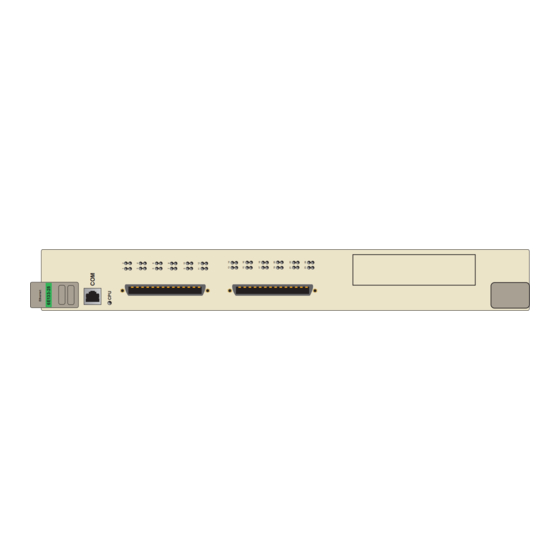
Page 14: 6E12X-26 And 6E13X-25 Overview
The 6E12X-26 and 6E13X-25 can be used to connect individual high-bandwidth user devices, such as workstations, and to provide a central switching point for multiple Ethernet segments using devices such as Cabletron Systems HubSTACK or other third party stackable devices. Figure 1-1 displays the 6E122-26 and 6E132-25. The... - Page 15 Ethernet 6E122-26 Network Ports 1-24 Fast Ethernet Interface Module Ports 25 and 26 Figure 1-1 The 6E122-26 and 6E132-25 6E122-26, 6E132-25, 6E123-26 and 6E133-25 User’s Guide 6E12X-26 and 6E13X-25 Overview Ethernet 6E132-25 COM Ports System LEDs Port Status LEDs Network...
-
Page 16: Connectivity
Chapter 1: Introduction 1.3.1 Connectivity The 6E122-26 and 6E132-25 connect to Ethernet networks or workstations through 24 RJ45 ports on the front panel. These ports support UTP connections up to 100 meters. The ports are IEEE 802.3 10BASE-T compliant. The 6E123-26 and 6E133-25 connect to Ethernet networks or workstations through two RJ21 connectors on the front panel. -
Page 17: Smarttrunk
Distributed, resilient links increase reliability and performance. • Multiple technologies are supported within a single trunk for maximum flexibility. For more information about SmartTrunk, refer to the Cabletron Systems SmartTrunk User’s Guide. 1.3.4 Management Management of the 6E12X-26 and 6E13X-25 is accomplished using Local Management tools or remote SNMP management stations. -
Page 18: Standards Compatibility
The 6E12X-26 and 6E13X-25 support a wide variety of industry standard MIBs including RFC 1213 (MIB II), RFC 1757 (RMON), RFC 1493 (Bridge MIB) and RFC 1354 (FIB MIB). A full suite of Cabletron Systems Enterprise MIBs provide a wide array of statistical information to enhance troubleshooting. 1.3.7... -
Page 19: Local Management Features
6E12X-26 and 6E13X-25, the optional Fast Ethernet Interface Modules and the 6C105 chassis. The associated High Speed Interface Module user’s guide provides detailed information about Local Management of the applicable HSIM. 6E122-26, 6E132-25, 6E123-26 and 6E133-25 User’s Guide 6E12X-26 and 6E13X-25 Overview... -
Page 20: Optional Features
Modules and High Speed Interface Modules, which add remote uplink capability. Cabletron Systems provides Fast Ethernet Interface Modules for the 6E12X-26 to support uplinks to 100 Mbps Ethernet backbones or high speed connections to local servers. The Fast Ethernet Interface Modules... -
Page 21: Document Conventions
Caution symbol. Contains information essential to avoid damage to the equipment. CAUTION Electrical Hazard Warning symbol. Warns against an action that could result in personal injury or death due to an electrical hazard. 6E122-26, 6E132-25, 6E123-26 and 6E133-25 User’s Guide Document Conventions... -
Page 22: Getting Help
Cabletron Systems Technical Writing Department via the following email address: TechWriting@cabletron.com Make sure to include the document Part Number in the email message. Before calling the Cabletron Systems Global Call Center, have the following information ready: • Your Cabletron Systems service contract number •... -
Page 23: Related Manuals
These manuals can be obtained from the World Wide Web in Adobe Acrobat Portable Document Format (PDF) at the following site: http://www.cabletron.com/ All documentation for the Cabletron Systems SecureFast VLAN NOTE Manager software is contained on the VLAN Manager CD-ROM. - Page 24 Chapter 1: Introduction 1-12 6E122-26, 6E132-25, 6E123-26 and 6E133-25 User’s Guide...
-
Page 25: Chapter 2 Network Requirements
To connect the 6E12X-26 and 6E13X-25 to a network so it can take advantage of the SmartTrunk feature, there are certain rules concerning port connections and configurations that must be followed for proper operation. Refer to the Cabletron Systems SmartTrunk User’s Guide for additional information. 6E122-26, 6E132-25, 6E123-26 and 6E133-25 User’s Guide CHAPTER 2 2.1) -
Page 26: 10Base-T Network
100BASE-FX FIBER OPTIC NETWORK Ports 25 and 26 of the 6E12X-26 support the Cabletron Systems FE-100FX and FE-100F3 fiber optic interface modules. The device at the other end of the fiber optic segment must meet the 100BASE-FX Fast Ethernet network requirements to operate at 100 Mbps. -
Page 27: Installation
Verify the contents of the carton as listed in Table 3-1 Contents of Shipping Carton Item 6E132-25, 6E122-26, 6E133-25 or 6E123-26 Release Notes RJ21 Angle Adapter (6E123-26 and 6E133-25 only) 6E122-26, 6E132-25, 6E123-26 and 6E133-25 User’s Guide CHAPTER 3 INSTALLATION Quantity Table 3-1. -
Page 28: 6E12X-26 And 6E13X-25 Options
Attach the strap to your wrist and plug the cable from the antistatic wrist strap into the ESD grounding receptacle at the upper right corner of the 6C105. 6E122-26, 6E132-25, 6E123-26 and 6E133-25 User’s Guide for installation instructions. The installation... - Page 29 Observe all precautions to prevent damage from Electrostatic Discharge (ESD). Examine the module for damage. If any damage exists, DO NOT install the module. Immediately contact the Cabletron Systems Global Call Center. To prevent damaging the backplane connectors in the following...
- Page 30 Chapter 3: Installation Slot Number Metal Back-Panel Figure 3-1 Installing an Interface Module 6E122-26, 6E132-25, 6E123-26 and 6E133-25 User’s Guide Ethernet 6E132-25 Circuit Card Card Guides 207602 Plastic Locking Tab Plastic Locking Tab...
-
Page 31: Connecting To The Network
Cabletron Systems SmartTrunk User’s Guide shipped with the modules.. Ports 1 through 24 on the 6E122-26 and 6E132-25 have RJ45 connectors for twisted pair connections. Ports 1 through 24 on the 6E123-26 and 6E133-25 have RJ21 connectors for twisted pair connections. Ports 25 and 26 of the 6E12X-26 support FE-100TX, FE-100FX, or FE-100F3 Fast Ethernet Interface Modules. -
Page 32: Connecting Utp Cables To Ports 1 Through 24 Of The 6E122-26 And 6E132-25
Connecting UTP Cables to Ports 1 Through 24 of the 6E122-26 and 6E132-25 Ports 1 through 24 of the 6E122-26 and 6E132-25 are 10BASE-T ports with internal crossovers. When connecting a workstation, use a straight-through cable. When connecting networking devices, such as another bridge, repeater, or router, use a crossover cable. - Page 33 Figure 3-3 Cable Pinouts - (RJ45) Crossover Cable Check that the twisted pair connection meets the dB loss and cable specifications outlined in If a link is not established, contact the Cabletron Systems Global Call Center. Refer to Section Repeat steps 1 through 3, above, until all connections have been made.
-
Page 34: Connecting Utp Cables To Ports 1 Through 24 Of The 6E133-25 And 6E123-26
Screw Hole Screw Screw Screw Hole Figure 3-4 6E133-25 and 6E123-26 Twisted Pair Connection 6E122-26, 6E132-25, 6E123-26 and 6E133-25 User’s Guide or, if using the RJ21 angle adapter RX (Receive) 207603... - Page 35 Verify that the 10BASE-T device at the other end of the twisted pair segment is ON and connected to the segment. 6E122-26, 6E132-25, 6E123-26 and 6E133-25 User’s Guide Screw Hole Screw Hole 3-5.
-
Page 36: Connecting A Twisted Pair Segment To The Fe-100Tx
Check that the twisted pair connection meets the dB loss and cable specifications outlined in If a link is not established, contact the Cabletron Systems Global Call Center. Refer to Section Repeat steps 1 through 4, above, until all connections have been made. - Page 37 Make sure that the twisted pair connection meets dB loss and cable specifications outlined in Confirm that the crossover switch is in the correct position. If a link is not established, contact the Cabletron Systems Global Call Center. Refer to Section 6E122-26, 6E132-25, 6E123-26 and 6E133-25 User’s Guide...
-
Page 38: Connecting A Fiber Optic Segment To The Fe-100Fx And Fe-100F3
FE-100FX and FE-100F3 The FE-100FX and FE-100F3 have an SC style network port (see Figure 3-7). Cabletron Systems supplies fiber optic cable that uses SC style connectors that are keyed to ensure proper crossing over of the transmit and receive fibers. - Page 39 Verify proper crossing over of fiber strands between the applicable port on the 6E12X-26 and the fiber optic device at the other end of the fiber optic link segment. 6E122-26, 6E132-25, 6E123-26 and 6E133-25 User’s Guide RX LED Connecting to the Network...
-
Page 40: Completing The Installation
Chapter 3: Installation Verify that the fiber connection meets the dB loss specifications outlined in Chapter If a link has not been established, contact the Cabletron Systems Global Call Center. Refer to Section COMPLETING THE INSTALLATION The 6E12X-26 and 6E13X-25 are now ready to be set up through Local Management. -
Page 41: Chapter 4 Troubleshooting
The four interface modules covered in this manual all share the NOTE same LANVIEW LEDs. USING LANVIEW The 6E12X-26 and 6E13X-25 use Cabletron Systems built-in visual diagnostic and status monitoring system called LANVIEW. The LANVIEW LEDs (Figure status to aid in diagnosing network problems. Refer to description of the LEDs. - Page 42 Chapter 4: Troubleshooting 6E122-26, 6E132-25, 6E123-26 and 6E133-25 User’s Guide Ethernet 6E122-26 CPU LED 207604 Figure 4-1 LANVIEW LEDs Receive (RX) Transmit (TX)
- Page 43 Color Amber Green Amber Green Green Amber 6E122-26, 6E132-25, 6E123-26 and 6E133-25 User’s Guide Table 4-1 LANVIEW LEDs State Power off. Blinking. Hardware failure has occurred. Solid. Resetting, normal power up reset. Blinking. Crippled. Solid. Testing. Solid. Functional. Booting. Blinks amber and green while booting.
-
Page 44: Fe-100Tx Led
Fast Ethernet Interface Module. The 10/100 LED and the Receive (RX) LED are shown in Table 4-2 Table 4-3 LED when the RX LED is on or off, respectively. 6E122-26, 6E132-25, 6E123-26 and 6E133-25 User’s Guide State Port enabled, and no activity. Flashing. Indicates activity. - Page 45 (RX) LED is off. Table 4-3 FE-100TX LED Indications When the RX LED Is Off Color 10/100 Green 6E122-26, 6E132-25, 6E123-26 and 6E133-25 User’s Guide Figure 4-2 FE-100TX LED Description FE-100TX is operating at 10 Mbps. FE-100TX is operating at 100 Mbps.
-
Page 46: Troubleshooting Checklist
RESET button is settings. pressed. 6E122-26, 6E132-25, 6E123-26 and 6E133-25 User’s Guide Table 4-4 Recommended Action Check the proper connection of the power cable and its access to a live outlet. -
Page 47: Using The Reset Button
RESET button. The module processor goes through a reset process of approximately 20 seconds. Additional module downtime may be added as the module reenters the network. 6E122-26, 6E132-25, 6E123-26 and 6E133-25 User’s Guide 4-3) resets the 6E12X-26 and 6E13X-25 Ethernet... - Page 48 Chapter 4: Troubleshooting 6E122-26, 6E132-25, 6E123-26 and 6E133-25 User’s Guide...
-
Page 49: Chapter 5 Local Management
Local Management screens and commands. The Local Management screens shown in this chapter are for NOTE the 6E122-26. The 6E132-25, 6E133-25 and 6E123-26 share most of the following Local Management screens. All Local Management functions specific to any of the interface modules are preceded by a Note to alert the reader. -
Page 50: Local Management Keyboard Conventions
SPACE bar BACKSPACE Key Arrow Keys [–] Key DEL Key 6E122-26, 6E132-25, 6E123-26 and 6E133-25 User’s Guide Function These are selection keys that perform the same Local Management function. For example, “Press ENTER” means that you can press either ENTER or RETURN, unless this manual specifically... -
Page 51: Management Terminal Setup
Plug the RJ45 connector at the other end of the cable into the RJ45-to-DB9 adapter (supplied in the kit). Connect the RJ45-to-DB9 adapter to the PC communications port. RJ45 COM Port Figure 5-1 Management Terminal Connection 6E122-26, 6E132-25, 6E123-26 and 6E133-25 User’s Guide Management Terminal Setup Ethernet 6E122-26 UTP Cable... -
Page 52: Connecting An Uninterruptible Power Supply (Ups)
Connect the RJ45 connector at one end of the cable to the COM port on the 6E12X-26 and 6E13X-25. Plug the RJ45 connector at the other end of the cable into the RJ45-to-DB9 male (UPS) adapter, Cabletron Systems Part No. 9372066. Connect the RJ45-to-DB9 male (UPS) adapter to the female DB9 port on the rear of the UPS device (refer to the particular UPS device’s user... -
Page 53: Management Terminal Setup Parameters
Keyboard Setup Menu Keys -> Auto Repeat -> Keyclick -> Margin Bell -> Warning Bell -> 6E122-26, 6E132-25, 6E123-26 and 6E133-25 User’s Guide Management Terminal Setup Table 5-2 VT Terminal Setup 80 Columns Interpret Controls No Auto Wrap Jump Scroll... -
Page 54: Telnet Connections
Names screen of either the 6C105 chassis, or the module. For additional information about community names, refer to Section 5.8, SNMP Community Names Screen. Refer to the instructions included with the Telnet application for information about establishing a Telnet session. 6E122-26, 6E132-25, 6E123-26 and 6E133-25 User’s Guide... -
Page 55: Accessing Local Management
Event Message Line Figure 5-3 Local Management Password Screen Enter the Password and press ENTER. The default Super-User access password is “public” or press ENTER. 6E122-26, 6E132-25, 6E123-26 and 6E133-25 User’s Guide Accessing Local Management Section 5.8. The following steps describe the Figure 5-3, displays. -
Page 56: Navigating Local Management Screens
Operational Mode that will be set for the module to see the applicable Local Management screen hierarchy. 6E122-26, 6E132-25, 6E123-26 and 6E133-25 User’s Guide 5.7), or the General Configuration screen 5.15). Depending on the Operational Mode set for Figure 5-8. - Page 57 Chassis Menu Password Main Menu Module Menu Figure 5-5 802.1Q Switching Mode, LM Screen Hierarchy 6E122-26, 6E132-25, 6E123-26 and 6E133-25 User’s Guide Accessing Local Management General Configuration SNMP Community Names SNMP Traps Chassis Environmental Port Redirect Function Module General Configuration...
-
Page 58: Selecting Local Management Menu Screen Items
Use the arrow keys to highlight the EXIT command at the bottom of the Local Management screen. Press ENTER. The Password screen displays and the session ends. 5-10 6E122-26, 6E132-25, 6E123-26 and 6E133-25 User’s Guide General Configuration SNMP Community Names SNMP Traps... - Page 59 1 and 2 until the Main Menu screen displays. Use the arrow keys to highlight the RETURN command at the bottom of the Main Menu screen. Press ENTER. The Password screen displays and the session ends. 6E122-26, 6E132-25, 6E123-26 and 6E133-25 User’s Guide Accessing Local Management 5-11...
-
Page 60: The Main Menu Screen
IEEE 802.1Q VLANs. Access the Chassis Configuration screen by using the arrow keys to highlight the CHASSIS menu item and pressing ENTER. The Chassis Configuration screen displays. Proceed to Section 5.6. 5-12 6E122-26, 6E132-25, 6E123-26 and 6E133-25 User’s Guide... -
Page 61: Chassis Menu Screen
SNMP community names, set SNMP traps, monitor the 6C105 environmental status, perform port redirect functions, and to configure the 6C105 for IEEE 802.1Q operation. Figure 5-8 Chassis Menu Screen 6E122-26, 6E132-25, 6E123-26 and 6E133-25 User’s Guide Section 5.12. Figure... - Page 62 This menu item will only display if one or more modules installed the chassis have been configured to operate as IEEE 802.1Q switches. When selected, this menu item opens the VLAN Main Menu screen. For details, refer to the Cabletron Systems Port Based VLAN User’s Guide. Section 5.7.7,...
-
Page 63: Chassis Configuration Screen
Figure 5-9 Chassis Configuration Screen The following briefly explains each Chassis Configuration screen field: MAC Address (Read-Only) Displays the base physical address of the chassis. 6E122-26, 6E132-25, 6E123-26 and 6E133-25 User’s Guide Chassis Configuration Screen Figure 5-9, allows the user to set the... - Page 64 Contains the rate at which the screens are updated. This setting determines how frequently (in seconds) information is updated on the screen. To enter a new update time, refer to 5-16 6E122-26, 6E132-25, 6E123-26 and 6E133-25 User’s Guide 5.7.1. describes how to change the Section Section 5.7.4.
-
Page 65: Setting The Ip Address
To set the IP address, perform the following steps: Use the arrow keys to highlight the IP Address field. Enter the IP address into this field using Decimal Dotted Notation (DDN) format. For example: 134.141.79.120 6E122-26, 6E132-25, 6E123-26 and 6E133-25 User’s Guide Chassis Configuration Screen Section 5.7.6. Section 5.7.7. -
Page 66: Setting The Subnet Mask
ENTERED”. Local Management does not alter the current value, but it does refresh the Subnet Mask field with the previous value. Use the arrow keys to highlight the SAVE command, then press ENTER. The changes are saved to memory. 5-18 6E122-26, 6E132-25, 6E123-26 and 6E133-25 User’s Guide... -
Page 67: Setting The Chassis Date
Setting the Chassis Time To set the chassis clock, perform the following steps: Use the arrow keys to highlight the Chassis Time field. Enter the time in a 24-hour format, HH:MM:SS. 6E122-26, 6E132-25, 6E123-26 and 6E133-25 User’s Guide Chassis Configuration Screen 5-19... -
Page 68: Entering A New Screen Refresh Time
Line at the top of the screen displays “SAVED OK”. If the entry is not valid, Local Management does not alter the current setting, but it does refresh the Screen Refresh Time field with the previous value. 5-20 6E122-26, 6E132-25, 6E123-26 and 6E133-25 User’s Guide ., type “064500” in the... -
Page 69: Setting The Screen Lockout Time
Line at the top of the screen displays “SAVED OK”. If the entry is not valid, Local Management does not alter the current setting, but it does refresh the Screen Lockout Time field with the previous value. 6E122-26, 6E132-25, 6E123-26 and 6E133-25 User’s Guide Chassis Configuration Screen 5-21... -
Page 70: Setting The Operational Mode
Figure 5-10 Operational Mode Warning Screen Use the arrow keys to highlight the YES command and press ENTER. The changes are saved, and all the modules installed in the chassis reboot. 5-22 6E122-26, 6E132-25, 6E123-26 and 6E133-25 User’s Guide WARNING! 1666... - Page 71 IP addresses, and be configured to act as Standalone devices in terms of Local Management via the 6C105 chassis. Section 5.15.9 provides additional instructions and rules that must be met before configuring the modules as SecureFast switches. 6E122-26, 6E132-25, 6E123-26 and 6E133-25 User’s Guide 5-23...
-
Page 72: Snmp Community Names Screen
Names screen, Figure Event Message Line Community Name public public public SAVE Figure 5-11 SNMP Community Names Screen 5-24 6E122-26, 6E132-25, 6E123-26 and 6E133-25 User’s Guide 5-11, displays. 6C105 LOCAL MANAGEMENT SNMP Community Names Access Policy read-only read-write super-user EXIT RETURN... -
Page 73: Establishing Community Names
Local Management. The community name assigned Super-User access is the only one that gives the user complete access to Local Management. 6E122-26, 6E132-25, 6E123-26 and 6E133-25 User’s Guide SNMP Community Names Screen This community name allows read-only access to the 6C105 MIB objects, and excludes access to security-protected fields of read-write or... - Page 74 Use the arrow keys to highlight SAVE at the bottom of the screen and press ENTER. The message “SAVED OK” displays. The community names are saved to memory and their access modes implemented. 5-26 6E122-26, 6E132-25, 6E123-26 and 6E133-25 User’s Guide Section 5.16.
-
Page 75: Snmp Traps Screen
Trap Community Name (Modifiable) Displays the Community Name included in the trap message sent to the Network Management Station with the associated IP address. 6E122-26, 6E132-25, 6E123-26 and 6E133-25 User’s Guide Figure 5-12. 6C105 LOCAL MANAGEMENT... -
Page 76: Configuring The Trap Table
Exiting without saving causes a “NOT SAVED?” message to NOTE appear above the SAVE command. Edits will be lost if they are not saved before exiting. The designated workstations now receive traps from the 6C105. 5-28 6E122-26, 6E132-25, 6E123-26 and 6E133-25 User’s Guide... -
Page 77: Chassis Environmental Screen
field will read either “Normal”, “Fault”, or “Not Installed”. Chassis Fan Status (Read-Only) Displays the current status of the 6C105 fan tray. This field will read either “Normal”, “Fault”, or “Not Installed”. 6E122-26, 6E132-25, 6E123-26 and 6E133-25 User’s Guide Chassis Environmental Screen Figure 5-13, displays. -
Page 78: Port Redirect Function Screen
PORT REDIRECT FUNCTION menu item and pressing ENTER. The Port Redirect Function screen, Figure 5-30 6E122-26, 6E132-25, 6E123-26 and 6E133-25 User’s Guide Setting the Operational Figure 5-14, allows the user to set 5-14, displays. - Page 79 Source Module [ n ] (Selectable) Allows a selected module [n] to be configured as a source module. 6E122-26, 6E132-25, 6E123-26 and 6E133-25 User’s Guide Port Redirect Function Screen 6C105 LOCAL MANAGEMENT...
-
Page 80: Displaying The Source And Destination Entries
To display the next screen, use the arrow keys to highlight NEXT. Press ENTER and the next screen of entries is displayed. To display the previous screen, use the arrow keys to highlight PREVIOUS. Press ENTER to view the entries in the previous screen. 5-32 6E122-26, 6E132-25, 6E123-26 and 6E133-25 User’s Guide... -
Page 81: Changing Source And Destination Ports
13 to save all the new settings at once. Use the arrow keys to highlight SAVE at the bottom of the screen. Press ENTER. The message “SAVED OK” is displayed. 6E122-26, 6E132-25, 6E123-26 and 6E133-25 User’s Guide Port Redirect Function Screen 5-33... -
Page 82: Module Selection Screen
Telnet session is connected. Module Type The Module Type field displays the type of interface module that is installed in each slot. 5-34 6E122-26, 6E132-25, 6E123-26 and 6E133-25 User’s Guide 6E122-26 LOCAL MANAGEMENT Module Selection Module Type Serial #... -
Page 83: Selecting A Module
Serial # Indicates the serial number of the module. The serial number of the device is necessary when calling the Cabletron Systems Global Call Center. Hardware Revision Reflects the hardware version of the module. 5.12.1 Selecting a Module To select an individual module to perform Local Management functions,... -
Page 84: Module Menu Screen
MODULE MENU SCREEN The Local Management screens shown in this chapter are for NOTE the 6E122-26. The 6E132-25, 6E133-25 and 6E123-26 share most of the following Local Management screens. All Local Management functions specific to any interface module are preceded by a note to alert the reader. - Page 85 The Network Tools function resides on the 6E12X-26 and 6E13X-25 and consists of a series of commands that allow the user to access and manage network devices. Section 5.30 utility. 6E122-26, 6E132-25, 6E123-26 and 6E133-25 User’s Guide 5.20. 5.26. explains how to use the Network Tools Module Menu Screen...
-
Page 86: Module Configuration Menu Screen
MODULE CONFIGURATION menu item and pressing ENTER. The Module Configuration screen displays. 5-38 6E122-26, 6E132-25, 6E123-26 and 6E133-25 User’s Guide Figure provides instructions on setting the operational 5-17, provides access to... - Page 87 Module Type: 6E122-26 Slot Number: X Figure 5-17 Module Configuration Menu Screen 6E122-26, 6E132-25, 6E123-26 and 6E133-25 User’s Guide Module Configuration Menu Screen 6E122-26 LOCAL MANAGEMENT Module Configuration Menu Firmware Revision: BOOTPROM Revision: XX.XX.XX GENERAL CONFIGURATION SNMP COMMUNITY NAMES SNMP TRAPS...
- Page 88 The SmartTrunk Configuration screen allows the user to logically group interfaces together to create a greater bandwidth uplink. Refer to the Cabletron Systems SmartTrunk User’s Guide for additional information. MODULE SPECIFIC CONFIGURATION The Module Specific Configuration Menu screen allows the user to configure ports or check system resources specific to the 6E12X-26 and...
-
Page 89: General Configuration Screen
IP Address (Modifiable) This display allows the IP address to be set for the 6E12X-26 and 6E13X-25. To set the IP address, refer to 6E122-26, 6E132-25, 6E123-26 and 6E133-25 User’s Guide General Configuration Screen Figure 5-18, allows the user to set the Figure 5-18, displays. - Page 90 Contains the rate at which the screens are updated. This setting determines how frequently (in seconds) information is updated on the screen. To enter a new update time, refer to Section 5.15.7. 5-42 6E122-26, 6E132-25, 6E123-26 and 6E133-25 User’s Guide...
- Page 91 This field allows the user to set the 6E12X-26 and 6E13X-25 to operate as a traditional switch (802.1D SWITCHING option), an IEEE 802.1Q switch (802.1Q SWITCHING option), or as a Cabletron Systems SecureFast switch (SECURE FAST VLAN option). In 802.1D SWITCHING mode, the 24 ports located on the front panel, and each Fast Ethernet Interface Module, and HSIM port(s) are bridged to each other.
- Page 92 2400. The baud rate setting for LM is automatically sensed. For details about how to configure the COM port for various applications, refer to Section 5.15.11. 5-44 6E122-26, 6E132-25, 6E123-26 and 6E133-25 User’s Guide Section 5.15.10...
-
Page 93: Setting The Ip Address
ENTERED”. Local Management does not alter the current value and refreshes the IP address field with the previous value. Use the arrow keys to highlight the SAVE command, then press ENTER. The warning screen shown in 6E122-26, 6E132-25, 6E123-26 and 6E133-25 User’s Guide General Configuration Screen Section 5.15.13. -
Page 94: Setting The Subnet Mask
To change the subnet mask from its default, perform the following steps: Use the arrow keys to highlight the Subnet Mask field. Enter the subnet mask into this field using Decimal Dotted Notation (DDN) format. For example: 255.255.255.0 5-46 6E122-26, 6E132-25, 6E123-26 and 6E133-25 User’s Guide WARNING! 174252... -
Page 95: Setting The Default Gateway
Default Gateway field with the previous value. Use the arrow keys to highlight the SAVE command. Press ENTER. The Event Message Line at the top of the screen displays “SAVED OK”. 6E122-26, 6E132-25, 6E123-26 and 6E133-25 User’s Guide General Configuration Screen Figure 5-19 displays. -
Page 96: Setting The Tftp Gateway Ip Address
Enter the date in an MM/DD/YYYY format. It is not necessary to add separators between month, day, and NOTE year numbers. For example, to set the date to 03/17/1997, type “03171997” in the Module Date field. 5-48 6E122-26, 6E132-25, 6E123-26 and 6E133-25 User’s Guide... -
Page 97: Setting The Module Time
“SAVED OK”. If the entry is not valid, Local Management does not alter the current value and refreshes the Module Time field with the previous value. 6E122-26, 6E132-25, 6E123-26 and 6E133-25 User’s Guide General Configuration Screen ., type “064500” in the... -
Page 98: Entering A New Screen Refresh Time
Line at the top of the screen displays “SAVED OK”. If the entry is not valid, Local Management does not alter the current setting, but it does refresh the Screen Lockout Time field with the previous value. 5-50 6E122-26, 6E132-25, 6E123-26 and 6E133-25 User’s Guide... -
Page 99: Setting The Operational Mode
If the 6E12X-26 and 6E13X-25 have been set to SECURE FAST VLAN, refer to your SecureFast documentation set to configure the devices for this type of operation. 6E122-26, 6E132-25, 6E123-26 and 6E133-25 User’s Guide General Configuration Screen (Section Figure 5-19 displays. -
Page 100: Setting The Management Mode
Use the arrow keys to highlight the SAVE command, then press ENTER. The warning screen shown in Use the arrow keys to highlight the YES command and press ENTER. The changes are saved and the module reboots. 5-52 6E122-26, 6E132-25, 6E123-26 and 6E133-25 User’s Guide (Section Figure 5-19 displays. 5.16). -
Page 101: Configuring The Com Port
CAUTION displays. Do not continue unless the outcome of the action is fully understood. 6E122-26, 6E132-25, 6E123-26 and 6E133-25 User’s Guide General Configuration Screen Setting the IP Address.) Read this entire... - Page 102 Exiting without saving causes the message “NOT SAVED -- PRESS SAVE TO KEEP CHANGES” to appear. Exiting without saving causes all edits to be lost. CAUTION 5-54 6E122-26, 6E132-25, 6E123-26 and 6E133-25 User’s Guide WARNING Section 5.15.12. If you 174252...
-
Page 103: Changing The Com Port Application
COM port application. If the module does not have a valid IP address and the changes are saved, refer to Appendix C reestablish COM port communications. 6E122-26, 6E132-25, 6E123-26 and 6E133-25 User’s Guide General Configuration Screen Application Local Management Session... -
Page 104: Clearing Nvram
Use the arrow keys to highlight YES and press ENTER. The message “CLEARING NVRAM. REBOOT IN PROGRESS...” displays. The 6E12X-26 and 6E13X-25 clear NVRAM and reboot. All user-entered parameters default to factory settings. 5-56 6E122-26, 6E132-25, 6E123-26 and 6E133-25 User’s Guide Figure 5-21 WARNING is displayed. 174251... -
Page 105: Enabling/Disabling Ip Fragmentation
Super-User access gives the user full management privileges, allows existing passwords to be changed, and all modifiable MIB objects for the Cabletron Container MIB and Internet MIB-II to be accessed. 6E122-26, 6E132-25, 6E123-26 and 6E133-25 User’s Guide SNMP Community Names Screen 5-57... - Page 106 Local/Remote Management. Access Policy (Read-Only) Indicates the access accorded each community name. Possible selections are as follows: read-only 5-58 6E122-26, 6E132-25, 6E123-26 and 6E133-25 User’s Guide Figure 5-22, displays. 6E122-26 LOCAL MANAGEMENT SNMP Community Names Community Name...
-
Page 107: Establishing Community Names
Use the arrow keys to highlight SAVE at the bottom of the screen and press ENTER. The message “SAVED OK” displays. The community names are saved to memory and their access modes implemented. 6E122-26, 6E132-25, 6E123-26 and 6E133-25 User’s Guide SNMP Community Names Screen This community name allows read and write access to the 6E12X-26 and 6E13X-25 MIB objects, excluding security protected fields for... -
Page 108: Snmp Traps Screen
Trap Destination (Modifiable) Indicates the IP address of the workstation to receive trap alarms. Up to eight different destinations can be defined. 5-60 6E122-26, 6E132-25, 6E123-26 and 6E133-25 User’s Guide 6E122-26 LOCAL MANAGEMENT SNMP Traps Firmware Revision: BOOTPROM Revision: XX.XX.XX... -
Page 109: Configuring The Trap Table
Using the arrow keys, highlight the SAVE option and press ENTER. The message “SAVED OK” displays on the screen. The designated workstations now receive traps from the 6E12X-26 and 6E13X-25. 6E122-26, 6E132-25, 6E123-26 and 6E133-25 User’s Guide SNMP Traps Screen 5-61... -
Page 110: Switch Configuration Screen
6C105 chassis. The module has a direct connection to every other slot in the chassis. 5-62 6E122-26, 6E132-25, 6E123-26 and 6E133-25 User’s Guide Figure 5-24, provides the basic setup Figure 5-24, displays ports 1 through 8. To view or... - Page 111 Allows the user to set the amount of time (in seconds) the 6E12X-26 and 6E13X-25 will keep an address in its switch table before discarding it. The modules will discard an address from their switch table if they do not receive a valid packet from the applicable address in the amount of time specified in the Age Time field.
-
Page 112: Setting The Sta
Chapter 5: Local Management Port # (Read-Only) Lists each switch port on the module. If the number of ports is greater than eight, then the additional ports are listed on subsequent screens. MAC Address (Read-Only) Displays the hardware address assigned to each listed port. -
Page 113: Setting The Age Time
Use the SPACE bar to toggle to either ENABLED or DISABLED. Use the arrow keys to highlight the SAVE command at the bottom of the screen. Press ENTER. The message “SAVED OK” is displayed. 6E122-26, 6E132-25, 6E123-26 and 6E133-25 User’s Guide Switch Configuration Screen 5-65... -
Page 114: Ethernet Full Duplex Configuration Screen
[STANDARD ENET] [STANDARD ENET] [STANDARD ENET] SAVE SET ALL PORTS: [FULL ] Figure 5-25 Ethernet Full Duplex Configuration Screen 5-66 6E122-26, 6E132-25, 6E123-26 and 6E133-25 User’s Guide Figure Figure 6E122-26 LOCAL MANAGEMENT Full Duplex Configuration Firmware Revision: BOOTPROM Revision: XX.XX.XX... - Page 115 SET ALL PORTS (Toggle) Ports 1 through 24 can be set all at once to either STANDARD or FULL from this field. To set all ports, refer to 6E122-26, 6E132-25, 6E123-26 and 6E133-25 User’s Guide Ethernet Full Duplex Configuration Screen Section 5.19.1.
-
Page 116: Setting The Operation Mode
Press the SPACE bar until you see FULL or STANDARD. Use the arrow keys to highlight the SAVE command on the bottom line of the screen. Press ENTER. The message “SAVED OK” is displayed. 5-68 6E122-26, 6E132-25, 6E123-26 and 6E133-25 User’s Guide... -
Page 117: Module Specific Configuration Menu Screen
Configuration Menu screen by using the arrow keys to highlight the MODULE SPECIFIC CONFIGURATION MENU menu item and pressing ENTER. The Module Specific Configuration Menu screen displays. 6E122-26, 6E132-25, 6E123-26 and 6E133-25 User’s Guide Module Specific Configuration Menu Screen provides instructions on setting the operational Figure... - Page 118 The High Speed Configuration screen for the 6E13X-25 allows management of the installed HSIM. For details, refer to the applicable HSIM User’s Guide. 5-70 6E122-26, 6E132-25, 6E123-26 and 6E133-25 User’s Guide 6E122-26 LOCAL MANAGEMENT Module Specific Configuration Menu Firmware Revision: BOOTPROM Revision: XX.XX.XX...
- Page 119 IEEE 802.1Q switch and the Management Mode has been set to STAND ALONE. When selected, this menu item opens the VLAN Main Menu screen. For details, refer to the Cabletron Systems Port Based VLAN User’s Guide. Section describes how to configure the modules to function as 802.1Q switches.
-
Page 120: System Resources Screen
The time in days/hours/minutes that the module has been continuously running. CPU Type (Read-only) Indicates the microprocessor used in the 6E12X-26 and 6E13X-25. 5-72 6E122-26, 6E132-25, 6E123-26 and 6E133-25 User’s Guide Figure 5-27, provides information 6E122-26 LOCAL MANAGEMENT System Resources Firmware Revision: BOOTPROM Revision: XX.XX.XX... -
Page 121: Setting The Reset Peak Utilization
Shows the peak percentage of maximum switching capacity, since last reset. Reset Peak Switch Utilization (Toggle) Allows the user to reset the Peak Switch Utilization field. The switch may be set to either YES or NO as described in Peak Switch Utilization field to the current system traffic. -
Page 122: High Speed Interface Configuration Menu Screen (6E12X-26 Only)
25 and 26, their current operating mode, and indicates if the ports are linked. This screen also allows the user to enable or disable Auto-Negotiation and set the Advertised Ability. 5-74 6E122-26, 6E132-25, 6E123-26 and 6E133-25 User’s Guide Section 5.23. Figure... - Page 123 10BASE-F or 100BASE-TX/FX device. • No Link – There is no link signal present and there is no valid physical connection to another device. 6E122-26, 6E132-25, 6E123-26 and 6E133-25 User’s Guide 6E122-26 LOCAL MANAGEMENT High Speed Interface Configuration Firmware Revision: BOOTPROM Revision: XX.XX.XX...
- Page 124 FE-100TX installed is capable of auto-negotiating the operational mode and no further user setup is required. configure an FE-100TX. 5-76 6E122-26, 6E132-25, 6E123-26 and 6E133-25 User’s Guide describes how to configure a port with an Section 5.22.3 describes how to...
-
Page 125: Configuring An Fe-100Fx Or Fe-100F3 In Port 25 Or 26
Press ENTER. The port now operates in the chosen mode. Use the arrow keys to highlight the SAVE command. Press ENTER. The message “SAVED OK” displays and Local Management saves the changes to memory. 6E122-26, 6E132-25, 6E123-26 and 6E133-25 User’s Guide Section 5.22.2 provides instructions for 5-77... -
Page 126: Configuring An Fe-100Tx In Port 25 Or 26
100BASE-TXFD (full duplex). To set the advertised ability, proceed as follows: Use the arrow keys to highlight the Desired Oper. Mode field. Use the SPACE bar to select the desired mode. 5-78 6E122-26, 6E132-25, 6E123-26 and 6E133-25 User’s Guide Section 5.22.4 Section 5.22.5... -
Page 127: Flash Download Screen
Access the Flash Download screen from the Module Specific Configuration screen by using the arrow keys to highlight the FLASH DOWNLOAD menu item and pressing ENTER. The Flash Download screen displays. 6E122-26, 6E132-25, 6E123-26 and 6E133-25 User’s Guide Flash Download Screen Figure 5-29, allows the user to Switch, for details. -
Page 128: Using Bootp
fields at the bottom of the Flash Download screen. describes how to download using TFTP. download using RUNTIME. using BootP. 5-80 6E122-26, 6E132-25, 6E123-26 and 6E133-25 User’s Guide 6E122-26 LOCAL MANAGEMENT Flash Download Download Method: [TFTP] Reboot After Download:... - Page 129 The IP address of the TFTP server to be used for the FLASH download is entered in this field. Download File Name (Selectable) The complete TFTP Server path and file name of the new image is entered in this field. 6E122-26, 6E132-25, 6E123-26 and 6E133-25 User’s Guide 5-81...
-
Page 130: Image File Download Using Tftp
ENTER. The message “TFTP DOWNLOAD. WILL COMMIT TO FLASH. REBOOT IN PROGRESS...” displays in the event message line at the top of the screen and the new image is downloaded into FLASH memory. 5-82 6E122-26, 6E132-25, 6E123-26 and 6E133-25 User’s Guide... -
Page 131: Image File Download Using Runtime
ENTER. The message “RUNTIME DOWNLOAD. WILL COMMIT TO FLASH.” displays in the event message line at the top of the screen and the new image is downloaded into FLASH memory. 6E122-26, 6E132-25, 6E123-26 and 6E133-25 User’s Guide Flash Download Screen 5-83... -
Page 132: Image File Download Using Bootp
ENTER. The message “BOOTP DOWNLOAD. WILL COMMIT TO FLASH. REBOOT IN PROGRESS...” displays in the event message line at the top of the screen and the new image is downloaded into FLASH memory. 5-84 6E122-26, 6E132-25, 6E123-26 and 6E133-25 User’s Guide... -
Page 133: Port Redirect Function Screen
Configuration Menu screen by using the arrow keys to highlight the PORT REDIRECT FUNCTION menu item and pressing ENTER. The Port Redirect Function screen displays. 6E122-26, 6E132-25, 6E123-26 and 6E133-25 User’s Guide Port Redirect Function Screen Setting the Operational Figure... - Page 134 Allows a selected port [n] to be changed to a source port. Destination Port [ n ] (Selectable) Allows a selected port [n] to be changed to a destination port. 5-86 6E122-26, 6E132-25, 6E123-26 and 6E133-25 User’s Guide 6E122-26 LOCAL MANAGEMENT Port Redirect Function Firmware Revision: BOOTPROM Revision: XX.XX.XX...
-
Page 135: Displaying The Source And Destination Entries
Use the SPACE bar to select either the ADD or DEL (delete) option. Press ENTER. This adds or deletes the port selections made in steps 2 and 4 and also updates the screen Source Port and Destination Port list. 6E122-26, 6E132-25, 6E123-26 and 6E133-25 User’s Guide Port Redirect Function Screen 5-87... - Page 136 Use the arrow keys to highlight SAVE at the bottom of the screen. Press ENTER. The message “SAVED OK” is displayed. This saves the new settings and updates the Source Interface and Destination Interface read-only fields. 5-88 6E122-26, 6E132-25, 6E123-26 and 6E133-25 User’s Guide...
-
Page 137: Broadcast Suppression Screen
12345678910 12345678910 12345678910 12345678910 12345678910 12345678910 12345678910 SAVE Figure 5-31 Broadcast Suppression Screen 6E122-26, 6E132-25, 6E123-26 and 6E133-25 User’s Guide Broadcast Suppression Screen Figure 5-31, allows the user to set a Section 5.15.9, 6E122-26 LOCAL MANAGEMENT Broadcast Suppression Peak Rate... -
Page 138: Setting The Threshold
Type in the numbers for the desired limit in increments of 10. Use the arrow keys to highlight the SAVE command at the bottom of the screen. Press ENTER. The message “SAVED OK” is displayed. 5-90 6E122-26, 6E132-25, 6E123-26 and 6E133-25 User’s Guide... -
Page 139: Setting The Reset Peak Switch
5.25.2 Setting the Reset Peak Switch To set the Reset Peak Switch field to YES or NO, proceed as follows: Use the arrow keys to highlight the Reset Peak field for the selected port. Press the SPACE bar to select YES or 3NO. - Page 140 RMON STATISTICS The RMON Statistics screen displays all the statistics gathered by the embedded RMON agent built-in to the 6E12X-26 and 6E13X-25. 5-92 6E122-26, 6E132-25, 6E123-26 and 6E133-25 User’s Guide 6E122-26 LOCAL MANAGEMENT Module Statistics Menu Firmware Revision: BOOTPROM Revision: XX.XX.XX...
-
Page 141: Switch Statistics Screen
Figure 5-33 Switch Statistics Screen The Switch Statistics screen displays the following menu items: Interface # (Read-Only) Identifies the interface or port number. 6E122-26, 6E132-25, 6E123-26 and 6E133-25 User’s Guide Figure 5-33, lists the number of frames 6E122-26 LOCAL MANAGEMENT... -
Page 142: Using The Clear Counters Command
To reset all the statistics counters to zero, perform the following steps: Use the arrow keys to highlight the CLEAR COUNTERS field. Press ENTER, the counters for the selected port are reset to zero. 5-94 6E122-26, 6E132-25, 6E123-26 and 6E133-25 User’s Guide Section 5.27.1. -
Page 143: The Interface Statistics Screen
6E12X-26 and 6E13X-25 interfaces (ports 1 through 24 and Fast Ethernet Interface Modules and all backplane interfaces) with the exception of an HSIM installed in the 6E13X-25. Cabletron Systems HSIMs gather their own statistics, and may NOTE be viewed via the Local Management screens of the applicable HSIM. - Page 144 The InDiscards field displays the total number of inbound frames that were discarded, even though the frames contained no errors. This field may increment because the switch needed to free up buffer space, or the switch was being overutilized. InErrors (Read-only) This field displays the total number of inbound frames that have been...
- Page 145 The OutDiscards field displays the total number of outbound frames that were discarded, even though the frames contained no errors. This field may increment, because the switch needed to free up buffer space, or the switch was being overutilized. OutErrors (Read-only) This field displays the total number of outbound frames discarded...
-
Page 146: Displaying Interface Statistics
Press the SPACE bar to increment (or press the DEL (delete) key to decrement) the interface number. Press ENTER (neither the Interface # fields nor the statistics will change until ENTER is pressed). 5-98 6E122-26, 6E132-25, 6E123-26 and 6E133-25 User’s Guide Section 5.28.2. Section 5.28.1. -
Page 147: Using The Clear Counters Command
Ethernet interfaces, and any Fast Ethernet Interface Modules installed in the 6E12X-26. RMON Statistics are not gathered for an HSIM installed in the 6E13X-25. 6E122-26, 6E132-25, 6E123-26 and 6E133-25 User’s Guide RMON Statistics Screen 6E122-26 LOCAL MANAGEMENT RMON Statistics Firmware Revision: BOOTPROM Revision: XX.XX.XX... - Page 148 The Broadcast Pkts field displays the total number of good frames that were directed to the broadcast address. The value of this field does not include multicast frames. 5-100 6E122-26, 6E132-25, 6E123-26 and 6E133-25 User’s Guide Figure 5-35 shows that the data source for this...
- Page 149 FCS or a bad CRC. Total Packets (Read-only) This field displays the total number of frames (including bad frames, broadcast frames, and multicast frames) received on this interface. 6E122-26, 6E132-25, 6E123-26 and 6E133-25 User’s Guide RMON Statistics Screen 5-101...
- Page 150 Section 5.29.1. CLEAR COUNTERS (Command) This command is used to reset all statistic counters to zero. For details on how to use this field, refer to Section 5.29.2. 5-102 6E122-26, 6E132-25, 6E123-26 and 6E133-25 User’s Guide...
-
Page 151: Displaying Rmon Statistics
To reset all the statistics counters of the selected interface to zero, perform the following steps: Use the arrow keys to highlight the CLEAR COUNTERS field. Press ENTER, the counters for the selected index are reset to zero. 6E122-26, 6E132-25, 6E123-26 and 6E133-25 User’s Guide RMON Statistics Screen 5-103... -
Page 152: Network Tools
The commands are arp, bridge, defroute, netstat, ping, reset, show, traceroute, soft_reset, telnet, link_trap, and atm_stp_state. • Special Commands – Allow the user to exit from Network Tools. The commands are done, exit, and quit. 5-104 6E122-26, 6E132-25, 6E123-26 and 6E133-25 User’s Guide defroute reset link_trap 090829... -
Page 153: Built-In Commands
Network Tools. arp: Syntax: Description: 6E122-26, 6E132-25, 6E123-26 and 6E133-25 User’s Guide Shows the required command format. It indicates where arguments, if any, must be specified. Briefly describes the command and its uses. -
Page 154: Mac Address
-> arp -d 1 122.144.52.68 -> arp -s 1 22.44.2.3 00:00:0e:03:1d:3c -> arp -f 5-106 6E122-26, 6E132-25, 6E123-26 and 6E133-25 User’s Guide Each ARP cache entry lists the network interface that the device is connected to, the device’s network address or IP address, the device’s physical address or MAC address, and... - Page 155 Example: -> bridge disable all -> bridge enable 1 -> bridge disable 1 6E122-26, 6E132-25, 6E123-26 and 6E133-25 User’s Guide bridge [ENABLE/DISABLE] [IFNUM/ALL] The bridge command allows each bridge port to be enabled or disabled at the user’s request, either one at a time or all at once. Specifying a...
- Page 156 -> defroute delete # Default route is not currently set. -> 5-108 6E122-26, 6E132-25, 6E123-26 and 6E133-25 User’s Guide defroute [interface number] [IP address] The defroute command allows the user to view, set or delete the default IP route to a managed device through the specified interface.
- Page 157 Description: Options: Example: -> ping 122.144.40.10 122.144.40.10 is alive 6E122-26, 6E132-25, 6E123-26 and 6E133-25 User’s Guide netstat [option] The netstat command provides a display of general network statistics for the managed device. The netstat command must be used with one of the two display options.
- Page 158 Example: -> reset show: Syntax: Description: 5-110 6E122-26, 6E132-25, 6E123-26 and 6E133-25 User’s Guide reset The reset command allows a soft reset of the device. The user will be queried to confirm the reset command to insure against unwanted resets.
- Page 159 Options: Example: -> traceroute 122.144.11.52 # next-hop[0] : 122.144.60.45 # next-hop[1] : 122.144.8.113 # next-hop[2] : 122.144.61.45 # 122.144.11.52 is alive : 3 hops away. 6E122-26, 6E132-25, 6E123-26 and 6E133-25 User’s Guide Not Applicable OperStatus Forwarding 1500 enabled enabled disabled...
- Page 160 CAUTION Options: Example: -> soft-reset 5-112 6E122-26, 6E132-25, 6E123-26 and 6E133-25 User’s Guide soft_reset This command restarts the software image, which restores the user configuration settings from NVRAM. The user will be queried to confirm the reset command to ensure against unwanted resets.
- Page 161 Syntax: Description: Options: Example: 6E122-26, 6E132-25, 6E123-26 and 6E133-25 User’s Guide telnet [IP address] [Port #] The telnet command allows the user to communicate with another host (that supports Telnet connections) using the Telnet protocol. The user must specify the remote host using its IP address.
- Page 162 Spanning Tree Algorithm on all ATM interfaces. Syntax: Description: 5-114 6E122-26, 6E132-25, 6E123-26 and 6E133-25 User’s Guide link_trap [enable/disable/status] [PORT/all] The link_trap command allows link traps to be enabled or disabled when specifying a single port, or simultaneously when specifying “all”...
-
Page 163: Special Commands
Syntax: Description: Options: Example: -> done Connection closed 6E122-26, 6E132-25, 6E123-26 and 6E133-25 User’s Guide enable, disable, status -> atm_stp_state status Atm Stp is Enabled -> atm_stp_state disable -> atm_stp_state enable done The done command enables the user to exit from Network Tools and return to the Main Menu screen. - Page 164 Chapter 5: Local Management 5-116 6E122-26, 6E132-25, 6E123-26 and 6E133-25 User’s Guide...
-
Page 165: Appendix Aspecifications
This appendix provides operating specifications for the Cabletron Systems 6E132-25, 6E122-26, 6E133-25 and 6E123-26 Interface Modules. Cabletron Systems reserves the right to change these specifications at any time without notice. DEVICE SPECIFICATIONS Processor: Dynamic Random Access Memory (DRAM): FLASH Memory:... -
Page 166: Input/Output Ports
Ethernet Interface Modules (ports 25 and 26) 6E133-25 Ports 1 through 24 Slot for optional HSIM 6E122-26, 6E132-25, 6E123-26 and 6E133-25 User’s Guide Ethernet (10BASE-T compliant) with RJ45 type connectors. Slots accept three types of optional Fast Ethernet Interface Modules: the FE100-TX, FE100-FX and the FE-100F3. -
Page 167: Com Port Pinout Assignments
Electromagnetic Compatibility (EMC) The 6E12X-26 and 6E13X-25 meet the requirements of FCC Part 15, EN 50082-1, EN 55022, VCCI V-3, CSA C108.8, AS/NZS 3548, and 89/336/EEC. 6E122-26, 6E132-25, 6E123-26 and 6E133-25 User’s Guide COM Port Pinout Assignments Input/Output Output Output... - Page 168 Appendix A: Specifications 6E122-26, 6E132-25, 6E123-26 and 6E133-25 User’s Guide...
-
Page 169: Specifications
Unshielded Twisted Pair (UTP) cabling with an impedance between 85 and 111 ohms. The slide switch on the FE-100TX determines the crossover status of the cable pairs. If the switch is on the over. If the switch is on the over. -
Page 170: Fe-100Fx
Appendix B: FE-100TX, FE-100FX and FE-100F3 Specifications FE-100FX The FE-100FX shown in supports multimode fiber optic cabling. Specifications for the FE-100FX are listed below. Cable Type 50/125 µm fiber 62.5/125 µm fiber 100/140 µm fiber The transmitter power levels and receive sensitivity levels listed NOTE are peak power levels after optical overshoot. -
Page 171: Fe-100F3
FE-100F3 The FE-100F3 shown in supports single mode fiber optic cabling. Specifications for the FE-100F3 are listed in Table B-2 Cable Type 8/125 µm fiber 12/125 µm fiber The transmitter power levels and receive sensitivity levels listed NOTE are peak power levels after optical overshoot. A peak power meter must be used to correctly compare the values given above to those measured on any particular port. - Page 172 Appendix B: FE-100TX, FE-100FX and FE-100F3 Specifications 6E128-26, 6E138-25, 6E129-26 and 6E139-25 User’s Guide...
-
Page 173: Optional Installations
6E12X-26 and 6E13X-25 “Default” configuration settings. • Clear user-entered passwords stored in NVRAM and restore the default passwords. 6E122-26, 6E132-25, 6E123-26 and 6E133-25 User’s Guide APPENDIX C C.1) Local Management, for instructions on how to (Section C.2) - Page 174 Figure C-1 6E12X-26 and 6E13X-25 Mode Switch Switch definitions and positions are as follows: • Switches 1 through 4 – For Cabletron Systems use only. • Switch 5 – COM Port Autobaud. The default (OFF) position enables Autobaud sensing on the COM port for Local Management sessions.
-
Page 175: Setting The Mode Switch
BootP server, which contains the image file. • Switch 6 – After changing the position of switch 6 and restarting the module, the 6E12X-26 and 6E13X-25 request a new image download until they either receive a new image or the RESET button on the front panel is pressed. -
Page 176: Installing Optional Fast Ethernet Interface Modules
For instructions on installing a High Speed Interface Module NOTE (HSIM) in the 6E13X-25, refer to the applicable HSIM documentation. Optional Fast Ethernet Interface Modules Figure C-2 Fast Ethernet Interface Module Connector Location 6E122-26, 6E132-25, 6E123-26 and 6E133-25 User’s Guide Connectors... - Page 177 To remove a coverplate, refer to Remove the two screws fastening the coverplate to the standoffs. Save the screws. Lift and remove the coverplate from the top of the front standoffs. 6E122-26, 6E132-25, 6E123-26 and 6E133-25 User’s Guide Figure C-3 and proceed as follows:...
- Page 178 When inserting the Fast Ethernet Interface Module into the motherboard connector ensure that the pins do not bend, as CAUTION this can damage both the Fast Ethernet Interface Module and the motherboard connector. 6E122-26, 6E132-25, 6E123-26 and 6E133-25 User’s Guide Rear Standoff Front Standoffs...
- Page 179 Ensure that the Fast Ethernet Interface Module seats flush on the standoffs. Secure the Fast Ethernet Interface Module with the screws saved in steps 1 and 2. Installation is complete. 6E122-26, 6E132-25, 6E123-26 and 6E133-25 User’s Guide Module Module Connector Rear...
- Page 180 Appendix C: Mode Switch Bank Settings and Optional Installations 6E122-26, 6E132-25, 6E123-26 and 6E133-25 User’s Guide...
- Page 181 5-16 Chassis date 5-16 Chassis Environmental Screen 5-29 Chassis Environmental screen 5-14 Chassis Menu screen 5-13 Chassis time 5-16 6E122-26, 6E132-25, 6E123-26 and 6E133-25 User’s Guide INDEX Chassis Uptime 5-17 Clear NVRAM 5-45 Clearing NVRAM 5-56 COM port...
- Page 182 Installing into the chassis 3-2 Interface Statistics screen 5-98 IP address 5-16, 5-41, 5-45 IP Fragmentation 5-45, 5-57 Index-2 6E122-26, 6E132-25, 6E123-26 and 6E133-25 User’s Guide Keyboard conventions 5-2 LANVIEW LEDs 4-1 Last Image File Name 5-81 Last Image Server IP 5-81...
- Page 183 Chassis Environmental Screen 5-29 Chassis Menu screen 5-13 Ethernet Full Duplex Configuration screen 5-66 6E122-26, 6E132-25, 6E123-26 and 6E133-25 User’s Guide Flash Download screen 5-79 General Configuration screen 5-41 High Speed Interface screen 5-74 Interface Statistics screen 5-95 Main Menu screen 5-12...
- Page 184 NVRAM installed 5-73 peak switch utilization 5-73 reset peak switch utilization 5-73 TFTP Gateway IP Addr 5-42, 5-48, 5-81 Trap table configuration 5-28, 5-61 Traps enable 5-28 Troubleshooting 4-1 checklist 4-6 Unpacking 3-1 Index-4 6E122-26, 6E132-25, 6E123-26 and 6E133-25 User’s Guide...