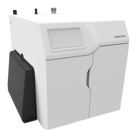
Zenith HydroTap G5 Quick Start Installation Manual
Command centre chilled, chilled/sparkling models
Hide thumbs
Also See for HydroTap G5:
- User manual (44 pages) ,
- Quick start installation manual (36 pages) ,
- Installation instructions manual (32 pages)
Table of Contents
Advertisement
Quick Links
Advertisement
Table of Contents

Related Manuals for Zenith HydroTap G5


Summary of Contents for Zenith HydroTap G5
- Page 1 Start Installation Guide Zenith HydroTap G5 Command Centre Chilled, Chilled/Sparkling models AFFIX PRODUCT LABEL HERE Visit our website to download the manuals Quick Start Installation Guide 807120NZ v1.00 01.21 G5 C CS Quick Start Guide...
-
Page 2: Table Of Contents
Table of contents SECTION 1: Using the instructions ..............3 SECTION 2: IMPORTANT SAFETY INSTRUCTIONS ..........4 SECTION 3: WARNINGS AND REGULATORY INFORMATION ......6 SECTION 4: Technical data ................8 SECTION 5: Supplied parts checklist ..............9 SECTION 6: Set up the ventilation ..............10 SECTION 7: Fit the carbonation valve ............... -
Page 3: Section 1: Using The Instructions
SECTION 1: Using these instructions Before you start This document is a Quick Start Installation Guide. For further details on installing and operating your HydroTap download & read the Command Centre installation and user instructions , which can be found online at: zenithwater.co.nz Read and use the instructions supplied with individual kit components for a safe installation. -
Page 4: Section 2: Important Safety Instructions
The Zenith HydroTap Command Centre range uses either HIGHLY FLAMMABLE R290, R600a or R134A refrigerant under pressure. Check the rating plate or contact Zenith before starting work. Maintenance of the refrigeration unit must be carried out by an accredited service provider or qualified refrigeration technician. - Page 5 The vent kit supplied must be fitted. Frost protection If the HydroTap G5 is located where the ambient air temperature could fall below 5ºC when the system is not in use, do not turn off the Command Centre electrically.
-
Page 6: Section 3: Warnings And Regulatory Information
• Connect only to a potable (wholesome cat1) mains water supply. • Never locate the system near, or clean with water jets. • Do not expose the Zenith HydroTap to the elements of nature. • Use of tools can be hazardous. Assess the risks before you start. - Page 7 When positioning the appliance, ensure the power supply cord is not trapped or damaged. If the power supply cord is damaged it must be replaced by a Zenith service provider or a qualified electrician. • Do not locate multiple portable socket-outlets or portable power supplies at the rear of the appliance.
-
Page 8: Section 4: Technical Data
SECTION 4: Technical data Technical data Power rating Dimensions Weight Model W x D x H (mm) (kg) CS100 0.37 330 (500) x 477 x 333 36.5 C100 0.34 330 (500) x 470 x 333 24.2 0.16 330 x 470 x 333 24.2 CS Home 0.18... -
Page 9: Section 5: Supplied Parts Checklist
* supplied with 1.2kg cylinder / adjustable regulator combination. Note: Mains water isolation valve is not supplied with the kit. Contact Zenith for the full range of consumables and accessories. Quick Start Installation Guide 807120NZ v1.00 01.21 G5 C CS Quick Start Guide... -
Page 10: Section 6: Set Up The Ventilation
SECTION 6: Set up the ventilation Use of tools can be hazardous. Assess the risks before you start. Use instructions supplied with individual kit parts. A clearance envelope around all Command Centres must be provided to allow ventilation for the safe and effective use of the HydroTap system. - Page 11 SECTION 6: Set up the ventilation CS100 & C100 models • Cold air is drawn in through the inlet vent and gap provided by the door buffers. • Warm air is exhausted through vent tray. • Inlet vent is mounted over cupboard side, door or floor cut-out (see below).
- Page 12 (supplied) All models If cupboard temperature exceeds 35°C, additional ventilation is required. Contact your Zenith service provider for options (including additional vents and fan kit). Quick Start Installation Guide 807120NZ v1.00 01.21 G5 C CS Quick Start Guide...
-
Page 13: Section 7: Fit The Carbonation Valve
Fit the carbonation valve SECTION 7: Chilled sparkling installations Avoid SPARKLING outlet Command Centre Carbonation valve flow adjustment • Use a 6mm Allen key or a large flat-blade screwdriver to adjust the valve. • Rotate the adjustment screw anti-clockwise to increase, and clockwise to decrease the flow. -
Page 14: Section 8: Connect The Water Supply
Connect the water supply SECTION 8: Valves and fittings must be sealed with PTFE tape if compression seals are not included. Note: Mixer tap installations also use a ‘Tee piece’ as part of the water supply plumbing connections, see the Tap installation instructions supplied with the Mixer Tap to connect the water supply if using the mixer tap option. -
Page 15: Section 9: Install The Co2 Cylinder And Regulator
SECTION 9: Install the CO2 cylinder and regulator Be aware of the risks of hazards which could cause harm when handling compressed CO2. Read the important safety instructions at the start of this instruction manual. Assess the risks before starting the installation. Secure the cylinder Ensure these is sufficient space to safely secure the cylinder and regulator. - Page 16 SECTION 9: Install the CO2 cylinder and regulator CO2 regulator identification Universal G5 regulator Cylinder pressure Braided hose Outlet connection pressure Regulator control knob Cylinder connection 1.2kg cylinder non-adjustable regulator Regulator control knob Braided hose connection Cylinder connection Quick Start Installation Guide 807120NZ v1.00 01.21 G5 C CS Quick Start Guide...
- Page 17 SECTION 9: Install the CO2 cylinder and regulator Fit the regulator and connect the gas hose • Ensure all mating surfaces are clean. • Turn the regulator OFF. • Check the regulator and hose seals, inside the connectors. • Connect the gas hose to the regulator. •...
- Page 18 SECTION 9: Install the CO2 cylinder and regulator Adjust the regulator Universal G5 regulator Outlet pressure Regulator control knob • Check the regulator is turned all the way OFF (anti-clockwise). • Turn the gas ON using the cylinder valve (2.64Kg cylinder), (anti-clockwise). •...
- Page 19 SECTION 9: Install the CO2 cylinder and regulator Test for leaks Care must be taken when working with high pressure carbon dioxide, and in no case should the normal operating pressure of 3.0 bar be exceeded. • Apply soapy water to the gas connections (see below), using a brush. •...
-
Page 20: Section 10: Connect The Command Centre
C res SECTION 10: Connect the Command Centre Generic installation instructions MAINS CHILLED OUTLET For HydroTap, mixer tap and any optional accessories, use instructions supplied with individual kit components. Mains power cable CS75 res Braided hose HydroTap MAINS CHILLED SPARKLING OUTLET OUTLET Command... - Page 21 C 175 comm SECTION 10: Connect the Command Centre CS100 models The foam insulation supplied CHILLED MAINS Mains OUTLET Water must be fitted over the WHITE and BLUE pipes BLUE WHITE check which way round still / sparkling CS 175 comm CHILLED MAINS SPARKLING...
- Page 22 B res comm SECTION 10: Connect the Command Centre C40, C100 models MAINS MIXER MIXER BOILING BYPASS VENT BYPASS Mains The foam insulation supplied Water must be fitted over the BLUE pipe BLUE C 175 comm CHILLED MAINS OUTLET C Comm check which way round still / sparkling CS 175 comm...
- Page 23 C res SECTION 10: Connect the Command Centre CS Home models MAINS CHILLED Mains OUTLET The foam insulation supplied must be Water fitted over the WHITE and BLUE pipes BLUE WHITE CS75 res MAINS CHILLED SPARKLING OUTLET OUTLET CS Res Diagram for illustrative purposes only.
- Page 24 BA res comm SECTION 10: Connect the Command Centre C Home models MAINS MIXER MIXER BOILING BYPASS VENT BYPASS Mains The foam insulation supplied AMBIENT Water OUTLET must be fitted over the BLUE pipe BLUE C res MAINS CHILLED OUTLET C Res CS75 res Diagram for illustrative purposes only.
-
Page 25: Section 11: Commissioning
SECTION 11: Commissioning User Guide page Unpack, moisten Adjust o-rings & fit filter carbonation valve Filter flush Connect electricity Flush 10 Litres through Monitor display screen TANK FLUSH 12:12 PM Follow the prompts to flush fresh water through the tank/s 3 times as shown by the cycle counter/s. The tank/s will fill automatically but when prompted use the tap to dispense and empty. - Page 26 Notes Quick Start Installation Guide 807120NZ v1.00 01.21 G5 C CS Quick Start Guide...
- Page 27 Notes Quick Start Installation Guide 807120NZ v1.00 01.21 G5 C CS Quick Start Guide...
-
Page 28: Contact Details
Refer to User Guide for operation and maintenance. Zenith Heaters Limited IRD/GST No. 95 640 729 18 Kawakawa Place, Westgate, Auckland 0814 New Zealand Ph: +(64 9) 838 8612 | Free Call 0800 558 055 zenithwater.co.nz WMKA21821 AU02691 WMTS-105 Quick Start Installation Guide...