Table of Contents
Advertisement
Quick Links
Advertisement
Chapters
Table of Contents
Troubleshooting

Related Manuals for Bosch ACS 553


Summary of Contents for Bosch ACS 553
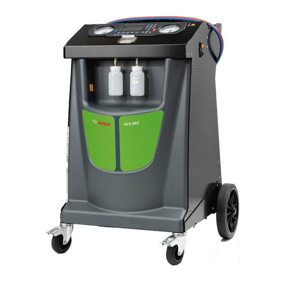
- Page 1 ACS 553 - ACS 553-P - ACS 563 - ACS 563-P en Repair instruction A/C Service Unit...
- Page 2 ACS 553, ACS 563 Service Manual Robert Bosch GmbH Franz-Oechsle-Straße 4 1119D-73201 Plochingen SERVICE: bosch.prueftechnik@bosch.com © Robert Bosch GmbH 1 689 975 295 2021-04-13 Robert Bosch GmbH...
-
Page 3: Table Of Contents
ACS 553, ACS 563 Service Manual Table of Contents Safety Warnings ....................4 Protective devices ......................7 PED directive 2014/68/EU ....................7 Machine handling ......................7 Target group ........................8 Introduction ......................9 Introduction ........................10 Unit Specifications ......................22 Maintenance Schedule .................... -
Page 4: Safety Warnings
CAUTION: Used without the safety alert symbol indicates a potentially hazardous situation which, if not avoided, may result in property damage. These safety messages cover situations Bosch is aware of. Bosch cannot know, evaluate, or advise you as to all possible hazards. You must verify that conditions and procedures do not jeopardize your personal safety. - Page 5 ACS 553, ACS 563 Service Manual WARNING: To prevent personal injury, ALLOW ONLY QUALIFIED PERSONNEL TO OPERATE THE MACHINE. Before operating the machine, read and follow all instructions and warnings in this manual. The operator must be familiar with air conditioning and refrigeration systems, refrigerants, and the dangers of pressurized components.
- Page 6 R1234yf ( ACS 563) or R134a (ACS 553) refrigerant. Do not attempt to adapt the machine for another refrigerant. Do not mix refrigerant types through a system or in the same container; mixing of refrigerants will cause severe damage to the machine and the vehicle air conditioning system.
-
Page 7: Protective Devices
• High pressure switch. • Recovery group. • Piping. Call Bosch service center to get technical specifications for each part listed. Machine handling The unit should normally be moved on flat surfaces with a maximum slope of 15 ° and on the four wheels, avoiding excessive shaking. -
Page 8: Target Group
ACS 553, ACS 563 Service Manual Target group Repair of the ACS 553, ACS 563 may only be performed by service technicians, trained in handling of refrigerants, personal protective equipment, refrigerant leakage prevention, handling of charging, leak detection and proper disposal. -
Page 9: Introduction
Introduction ACS 553, ACS 563 Service Manual I n troduct i o n Introduction .......................10 Control Panel Functions ....................11 Icon Legend ........................11 Glossary .......................... 12 Setup Menu ........................12 General Maintenance ..................... 15 Electrical Protection ....................... 15 Tank Fill ........................... 15 Filter Maintenance ...................... -
Page 10: Introduction
Introduction ACS 553, ACS 563 Service Manual Introduction These units are designed to be compatible with existing service equipment and standard service procedures. These machines utilize a single-pass system that meets specifications for recycled refrigerant. Follow recommended service procedures for the containment of refrigerant. -
Page 11: Control Panel Functions
Introduction ACS 553, ACS 563 Service Manual Control Panel Functions ARROW UP moves selection of a menu item to the previous item. ARROW DOWN moves selection of a menu item to the following item. ARROW RIGHT scrolls to next screen. -
Page 12: Glossary
• Select Functions to access the following designed specifically for this machine has functions. refrigerant disposable capacity of 7.8 kg, except the ACS 553 has a disposable capacity of A/C Perfomance Test 8.8 kg. Performs a pressure test on an A/C system of Machine: Model No. - Page 13 POE) into the oil injection port, before starting Firmware Update the function. To upgrade the firmware through a USB stick or via WiFi (with Bosch WiFi dongle - optional -). • Select BACK icon to return to the Setup The display shows five selection options: Menu.
- Page 14 Introduction ACS 553, ACS 563 Service Manual WiFi Configuration Pump Maintenance To configure the WiFi connection to the machine. Displays the amount of time remaining until The display shows five selection options: the next vacuum pump oil change is needed.
-
Page 15: General Maintenance
If the protection fuses are blown, the tank is empty, or has insufficient refrigerant power supply of ACS 553 - ACS 563 is cut off. for transfer, tank fill will stop. 6. Connect the low pressure service hose (blue) to the liquid connector on a full source tank. -
Page 16: Filter Maintenance
Introduction ACS 553, ACS 563 Service Manual Filter Maintenance 5. Look at the new filter. Verify both O-rings are lubricated and correctly located in the The filter is designed to trap acid and particulates, grooves as shown in Figure 1-5. -
Page 17: Vacuum Pump Maintenance
Introduction ACS 553, ACS 563 Service Manual Vacuum Pump Maintenance NOTE: Vacuum pump oil must be changed with every filter change, every 100 hours pump runs or more often as necessary. 1. Call up the Main Menu. 2. Select NEXT icon. -
Page 18: Edit Print Header
Setting menu) appearing in the header on internal scale is always calibrated. To perform each printout: this check make use of Bosch calibration kit 1. Call up the Main Menu. (optional) including sample weight and magnet. 2. Select NEXT icon. -
Page 19: Pressure Decay Leak Test (For R1234Yf Only)
Introduction ACS 553, ACS 563 Service Manual Printer kit installation Pressure Decay Leak Test (for R1234yf only) WARNING: Disconnect the unit from the power source before beginning This function is available on Maintenance menu. service work. Incorrect use or To ensure a safe, environmentally friendly,... -
Page 20: Calibration Check Kit Installation (Optional)
Introduction ACS 553, ACS 563 Service Manual Calibration check kit installation Refrigerant conversion kit (optional) WARNING: Disconnect the unit from the power source before beginning For the magnet installation, refer to Figure 1-10. service work. Incorrect use or 1. Plug the magnet (1) within the housing connections can cause electrical underneath the machine base. - Page 21 Introduction ACS 553, ACS 563 Service Manual 10. The vacuum function is finished when the 27. Follow the instructions on display to replace display shows: filter (refer to “Filter Maintenance” in the Maintenance section) and vacuum pump oil SERVICE VACUUM COMPLETE (refer to the “Vacuum Pump Maintenance”...
-
Page 22: Unit Specifications
Introduction ACS 553, ACS 563 Service Manual UNIT SPECIFICATIONS ACS 563 ACS 553 Refrigerant R1234yf R134a ISV total capacity 10 l 10 l (water capacity) Internal Vessel Maximum Storage 8.934 kg of R1234yf 9.827 kg of R134a Capacity (kg of refrigerant) (7.8 kg manageable by operator) - Page 23 Introduction ACS 553, ACS 563 Service Manual ACS 563 ACS 553 Compressor Power 1/4 HP 1/4 HP Displacement 8.85 cm 8.85 cm Recovery performance (maximum, liquid phase) Power Supply 230 Vac/1 50/60 Hz 230 Vac/1 50/60 Hz Vacuum Pump Free Air Displacement 70 l/min (2.5 CFM)
-
Page 24: Maintenance Schedule
Introduction ACS 553, ACS 563 Service Manual MAINTENANCE SCHEDULE MAINTENANCE TASK RECOMMENDED INTERVAL After (SEE TABLE) of refrigerant has been filtered. Refer to “Filter Change” in the Maintenance section of this manual. Model Replacement filter at: Change filter R134a 68 kg (alert 56 kg) -
Page 25: Diagnostics And Testing
Diagnostics and Testing ACS 553, ACS 563 Service Manual D i a g n o s t i c s and Testing Functional Check ....................26 Updating System Software Instruction ................26 Recover Function ....................... 27 Charge Function ......................... 28 Diagnostics and Testing ..................30 Service Center Menu ...................... -
Page 26: Functional Check
Diagnostics and Testing ACS 553, ACS 563 Service Manual FUNCTIONAL CHECK Prior to performing a functional or diagnostic 14. The unit will go through a file updating period check, make sure the software version is (it can take several minutes) to finalize the current. -
Page 27: Recover Function
Diagnostics and Testing ACS 553, ACS 563 Service Manual 11. After the recovery, the machine performs an N O T E : R e f e r t o S c a l e C a l i b r a t i o n a t... -
Page 28: Charge Function
Diagnostics and Testing ACS 553, ACS 563 Service Manual Machine is asking to input: Charge Function • Oil inject (Yes or No). If select No unit don’t inject any oil. 1. Connect (or verify) both service hoses to • Oil amount: xxx ml (is possible set as ml, the test tank and turn the quick couplers oz or lb). - Page 29 Diagnostics and Testing ACS 553, ACS 563 Service Manual 8. If the amount of refrigerant is sufficient 11. If the charge was cancelled, Charge to charge the system to completion, the complete will change to Charge cancelled display will show hoses compensation a...
-
Page 30: Diagnostics And Testing
Diagnostics and Testing ACS 553, ACS 563 Service Manual DIAGNOSTICS AND TESTING NOTE: These are the Service Options at the time of printing this service manual. Some options may be added or deleted in future circuit board and software updates and revisions. -
Page 31: Calibrate Load Cells
Diagnostics and Testing ACS 553, ACS 563 Service Manual Calibrate load cell NOTE: DO NOT DISTURB unit during weight calibration. All units include load cell scale: ISV Load Cell. After 5 seconds: ISV Load Cell Calibration 1. Remove the internal storage vessel (ISV) from the scale. -
Page 32: Output Test
Diagnostics and Testing ACS 553, ACS 563 Service Manual 8. If the calculation is accepted, the following Output Test is displayed: The Output Test checks the electrical outputs from the power board and wiring harnesses to the various solenoids, fan, vacuum pump, and compressor. -
Page 33: Input Test
Diagnostics and Testing ACS 553, ACS 563 Service Manual 4. When the test is complete, select BACK Calibrate air flow (for R1234yf only) icon to return to the Service Menu. The air flow inside the unit must be present at... -
Page 34: A/C Unit Internal Clearing
Diagnostics and Testing ACS 553, ACS 563 Service Manual A/C unit internal clearing 5. The vacuum pump should turn on and the time begins to count down. Process will stop The A/C unit internal clearing is used to early if sufficient vacuum level is achieved. -
Page 35: End User Install
Diagnostics and Testing ACS 553, ACS 563 Service Manual 8. If the Inlet pressure rises above 0.35 bar Maintenance Counters during the Service Vacuum, any outputs Maintenance Counters record the number of times that are ON will turn OFF and the vacuum a maintenance function has been performed. - Page 36 Diagnostics and Testing ACS 553, ACS 563 Service Manual 7. Scroll to the next desired Maintenance Counter. If none is desired, select BACK icon to return to the Service Menu. The list of available items follows in the table: Display...
-
Page 37: Keypad Test
Diagnostics and Testing ACS 553, ACS 563 Service Manual Keypad Test Set Boot Mode Setting the Boot Mode makes it possible to boot into The Keypad Test is used to determine if the a mode other than Normal (default). The choices... -
Page 38: Refrigerant Identifier
Diagnostics and Testing ACS 553, ACS 563 Service Manual Refrigerant Identifier Enter plate only The Refrigerant Identifier is used to enable/ The Enter plate only is used to enable / disable disable the external refrigerant identifer. the vehicle data input page where only license plate is present as mandatory field. -
Page 39: Troubleshooting
Diagnostics and Testing ACS 553, ACS 563 Service Manual TROUBLESHOOTING Grounding, Noise, and Power Issues Power Issues The power applied to the unit must be from To provide proper protection and maximize a stable, low-impedance source. Long-term system reliability, it is important to consider stability must be within ±10% of the nominal... -
Page 40: Will Not Power-Up, No Display
Diagnostics and Testing ACS 553, ACS 563 Service Manual Will Not Power Up, No Display Will Not Fill Tank NOTE: The compressor should be running 1. Verify the unit is connected to a known good power source with a good ground and not during this test. -
Page 41: Stuck In Clearing
Diagnostics and Testing ACS 553, ACS 563 Service Manual Stuck In Clearing 11. Disconnect the manifold end of the compressor oil return line and check NOTE: The recover process begins with for pressure coming from the manifold low-side clearing. Low-side clearing activates (with compressor running). -
Page 42: Will Not Recover
Diagnostics and Testing ACS 553, ACS 563 Service Manual Will Not Drain Oil Will Not Recover NOTE: The compressor should be running 1. Verify the accumulator transducer is functioning properly. during this test. If it does not run, refer to 2. -
Page 43: Will Not Air Purge
Diagnostics and Testing ACS 553, ACS 563 Service Manual Will Not Air Purge Will Not Evacuate (Vacuum) 1. Verify the air purge solenoid (S6) is receiving NOTE: The vacuum pump should be running power and opening properly. during this test. If the pump does not run, •... -
Page 44: Fails Leak Test
Diagnostics and Testing ACS 553, ACS 563 Service Manual Fails Leak Test Vacuum Pump Not Running 1. Check gauges for vacuum. NOTE: To ensure an accurate leak test, it 2. If pressure is over 690 mBar (10 psi), clear is imperative that a thorough recovery and hoses. -
Page 45: Will Not Inject Oil
Diagnostics and Testing ACS 553, ACS 563 Service Manual Will Not Inject Oil Will Not Charge NOTE: There is no component that pumps 1. Verify the oil injection bottle is securely attached and contains an appropriate refrigerant into a system during the charge amount of oil. -
Page 46: Slow Charge
Diagnostics and Testing ACS 553, ACS 563 Service Manual Slow Charge Will Not Print (only for variants with printer) When the charge has slowed, the unit will enter the power charge process to build tank pressure 1. Does the printer have power? and temperature. -
Page 47: Power Board Troubleshooting
Diagnostics and Testing ACS 553, ACS 563 Service Manual Power Board Troubleshooting Control Board Troubleshooting 1. Possible reasons to replace the power 1. Possible reasons to replace control board: board: • Repeated read errors. • No power to any components. -
Page 48: Compressor Troubleshooting
Diagnostics and Testing ACS 553, ACS 563 Service Manual Compressor Troubleshooting 8. Enter the service menu, scroll to the Output test and select the Compressor test. 1. Check for proper power source and electrical connectors for damage or corrosion. ss00649 2. -
Page 49: Vacuum Pump Troubleshooting
Diagnostics and Testing ACS 553, ACS 563 Service Manual Vacuum Pump Troubleshooting Vacuum Pump Does Not Run 1. Check for proper power source and electrical 1. Check gauges for vacuum. connectors for damage or corrosion. 2. If pressure is over 0.7 bar (10 psi), recover Replace or repair as required. -
Page 50: Error Messages
Diagnostics and Testing ACS 553, ACS 563 Service Manual ERROR MESSAGES PROCEDURE ERROR/WARNING DESCRIPTION OF ERROR/WARNING Calibrate Load Cells Calibration failed! Difference between upper and lower Slope is out of range. limits is too great. Select RETRY or ESC icon... - Page 51 Diagnostics and Testing ACS 553, ACS 563 Service Manual PROCEDURE ERROR/WARNING DESCRIPTION OF ERROR/WARNING Oil Inject Oil inject error. Inject: XXXYY 1. Check if enough oil is present in oil bottle. 2. Check for oil inject tube kinks or cuts.
-
Page 52: Error Messages For Refrigerant Identifier (If Available)
Diagnostics and Testing ACS 553, ACS 563 Service Manual Error messages for refrigerant identifier (if available) PROCEDURE ERROR/WARNING DESCRIPTION OF ERROR/WARNING Refrigerant Identification Identifier Unstable Reading Possible reasons: Error 1 1. Sampling path problem: • Brass filter clogged and/or sample hose clogged. - Page 53 Diagnostics and Testing ACS 553, ACS 563 Service Manual PROCEDURE ERROR/WARNING DESCRIPTION OF ERROR/WARNING Refrigerant Identification Identifier Unstable Reading Possible reason: Error 3 1. Radio transmitters and arc welders. Refrigerant Identification Identifier Air Calibration Error Possible reasons: 1. Sampling path problem: •...
- Page 54 Diagnostics and Testing ACS 553, ACS 563 Service Manual PROCEDURE ERROR/WARNING DESCRIPTION OF ERROR/WARNING Refrigerant Identification Identifier Temperature Out of Possible reasons: Range 1. Ambient temperature below 10 °C. 2. Ambient temperature above 50 °C. Refrigerant Identification Identifier Pressure Out of...
-
Page 55: Electrical System Operation And Repair
Electrical ACS 553, ACS 563 Service Manual Electrical System Operation and Repair Electrical System Operation .................56 Power Board and Power Supply Operation ..............56 Power Board Connector Assignments ................56 Control Board Operation ....................57 Control Board Connector Assignments ................57 Control Board Functions .................... -
Page 56: Electrical System Operation
Electrical ACS 553, ACS 563 Service Manual ELECTRICAL SYSTEM OPERATION The electrical system provides the various P8: Solenoids S4-1, S4-2, S5-1, S5-2, S6, S7, voltage levels required for the machine to S8, S9, S11, S13, S14 and Fan. operate effectively. The power board, power... -
Page 57: Control Board Operation
Electrical ACS 553, ACS 563 Service Manual Control Board Operation Control Board Functions The Control Board, Figure 3-3, is mounted in 1. Reads Keypad the control panel and provides the control for • If a key does not respond, it’s most likely... -
Page 58: Sensors And Transducers
Electrical ACS 553, ACS 563 Service Manual Sensors and Transducers Control Board Software Updating Methods The sensors and transducers provide the To access the operational capability of the input and feedback data needed to control the unit, or to provide an interface to an external operation of unit. - Page 59 Electrical ACS 553, ACS 563 Service Manual ss01906 CONTROL BOARD Power Switch POWER SUPPLY ADJ. POWER BOARD Figure 3-4. Electrical Connections (Sheet 1 of 4) Robert Bosch GmbH 1 689 975 295 2021-04-13...
- Page 60 Electrical ACS 553, ACS 563 Service Manual ss01904 ISV TANK ACCUMULATOR TEMPERATURE PRESSURE SENSOR TRANSDUCER (TT) (AP) CONTROL BOARD AIR FLOW SENSOR (AF) LOW-SIDE PRESSURE SCALE TRANSDUCER ASSEMBLY (LSP) Figure 3-4. Electrical Connections (Sheet 2 of 4) NOTE: • The Air Flow Sensor (AF) is integrated in the fan.
- Page 61 Electrical ACS 553, ACS 563 Service Manual ss01905 S6 Air purge MANIFOLD POWER BOARD S4-1 Low-side inlet 1 S4-2 Low-side inlet 2 S5-1 High-side inlet 1 S5-2 High-side inlet 2 S7 Tank liquid S8 Oil drain S9 Vacuum S11 Recover...
- Page 62 Electrical ACS 553, ACS 563 Service Manual ss01907 CONTROL BOARD PRINTER ASSEMBLY (if present) VACUUM PUMP POWER BOARD FAN / AIR FLOW COMPRESSOR Figure 3-4. Electrical Connections (Sheet 4 of 4) 1 689 975 295 2021-04-13 Robert Bosch GmbH...
-
Page 63: Electrical System Repair
Electrical ACS 553, ACS 563 Service Manual ELECTRICAL SYSTEM REPAIR Replacement Power Board Remove Existing Power Board 1. Disconnect unit from the power source. WARNING: Disconnect the unit from 2. Remove the four screws under the control the power source before beginning panel. -
Page 64: Replacement Control Board
Electrical ACS 553, ACS 563 Service Manual Replacement Control Board Install Replacement Control Board NOTE: All control boards are shipped from the WARNING: Disconnect the unit from the factory without any software on board. Service power source before beginning service centers must follow these installation procedures work. -
Page 65: Replacement High-Pressure Cut-Out Switch
Electrical ACS 553, ACS 563 Service Manual Replacement High-Pressure Cut-Out 12. Select Languages and confirm. 13. Select AC/ACS model (unit require the input Switch 2 times) and confirm. 14. Set time/date and confirm. WARNING: Disconnect the unit from the 15. Set serial number (unit require the input power source before beginning service work. -
Page 66: Replacement Fan / Air Flow
Electrical ACS 553, ACS 563 Service Manual Replacement Fan / Air Flow 13. Connect the unit to a power source and place the power switch on. The fan should WARNING: Disconnect the unit from run. If the fan does not run, refer to the the power source before beginning Diagnostics and Testing section. -
Page 67: Replacement Scale Assembly
Electrical ACS 553, ACS 563 Service Manual Replacement Scale Assembly 3. Tilt the control panel down and secure with four screws. WARNING: Disconnect the unit from the 4. Connect the unit to the power source. power source before beginning service 5. -
Page 68: Plumbing And Mechanical System Operation And Repair
Plumbing and Mechanical ACS 553, ACS 563 Service Manual Plumbing and Mechanical System Operation and Repair Plumbing and Mechanical System Operation ............69 Compressor ........................69 Vacuum Pump ........................69 Internal Storage Vessel (ISV) ..................... 69 Manifold ..........................69 Fan / Air flow ........................69 Oil Drain Bottle ........................ -
Page 69: Plumbing And Mechanical System Operation
Plumbing and Mechanical ACS 553, ACS 563 Service Manual PLUMBING AND MECHANICAL SYSTEM OPERATION The plumbing and mechanical system Manifold is controlled by electrical impulses from The manifold assembly consists of solenoids: the electrical system. There are four main •... -
Page 70: Plumbing And Mechanical System Repair
Plumbing and Mechanical ACS 553, ACS 563 Service Manual PLUMBING AND MECHANICAL SYSTEM REPAIR Replacement Compressor CAUTION: To prevent personal injury, use caution when removing the WARNING: Disconnect the unit from compressor. The capacitor may still the power source before beginning be energized. - Page 71 Plumbing and Mechanical ACS 553, ACS 563 Service Manual MANIFOLD ASSEMBLY ss01942 COMPRESSOR OIL DRAIN NOTES: 1. Apply Loctite 222 to equivalent to threads. 2. Torque hose fittings to 8.5 ±0.5 Nm. Figure 4-1. Compressor Interconnection Diagram Robert Bosch GmbH...
-
Page 72: Replacement Vacuum Pump
Plumbing and Mechanical ACS 553, ACS 563 Service Manual Replacement Vacuum Pump 6. Remove the two nuts from isolators threaded studs that fastening the vacuum pump to the WARNING: Disconnect the unit from frame of the unit. the power source before beginning 7. - Page 73 Plumbing and Mechanical ACS 553, ACS 563 Service Manual Vacuum pump ss01943 High-side gauge Low-side gauge Manifold (Top View) ISV Assembly Liquid Vapor Oil Inject Figure 4-3. Plumbing Interconnection Diagram Robert Bosch GmbH 1 689 975 295 2021-04-13...
-
Page 74: Replacement Isv Assembly
Plumbing and Mechanical ACS 553, ACS 563 Service Manual Replacement ISV Assembly Installing Replacement ISV Assembly 1. Place the tank on the scale. WARNING: Disconnect the unit from 2. Secure the tank to the scale with two bolts. the power source before beginning 3. -
Page 75: Replacement Manifold
Plumbing and Mechanical ACS 553, ACS 563 Service Manual Replacement Manifold 9. Loosen the two rear screws and remove the 2 lateral screws (see Figure 4-4). WARNING: Disconnect the unit from 10. Remove the 2 vertical screws behind the the power source before beginning dryer filter (see Figure 4-4). - Page 76 Plumbing and Mechanical ACS 553, ACS 563 Service Manual NOTE: All wires must be clear of moving parts, pinch points, and sharp edges. LS Inlet 1 LS Inlet 2 Tank Liquid Solenoid (S4-1) Solenoid (S4-2) Solenoid (S7) Recover HS Inlet 1...
-
Page 77: Repairing Or Replacing A Solenoid
Plumbing and Mechanical ACS 553, ACS 563 Service Manual Repairing or Replacing a Solenoid Installing Solenoid 1. Lubricate the O-rings and threads on the WARNING: Disconnect the unit from new solenoid assembly. the power source before beginning 2. Install the repaired or replacement solenoid service work. -
Page 78: Replacing Check Valve
Plumbing and Mechanical ACS 553, ACS 563 Service Manual Replacing Check Valve Installing Replacement Check Valve 1. Lubricate the O-rings on the new check WARNING: Disconnect the unit from valve. the power source before performing 2. Install the new check valve and hand- service work. -
Page 79: Component Application Charts
Plumbing and Mechanical ACS 553, ACS 563 Service Manual COMPONENT APPLICATION CHARTS Manifold Component Application Chart, ACS 553 and ACS 563 Function Component LS Inlet 1 & 2 solenoid (S4) HS Inlet 1 & 2 solenoid (S5) Air Purge solenoid (S6) - Page 80 Plumbing and Mechanical ACS 553, ACS 563 Service Manual Fluid Flow Diagram Locations Function Figure No. Tank Fill Low Side Clearing Recover Oil Drain Vacuum 4-10 Vacuum Leak Test 4-11 Air Purge 4-12 Oil Inject (PAG/POE) 4-13 Pre-charge 4-14 (for R1234yf only if enabled)
-
Page 81: Flow Diagrams
Plumbing and Mechanical ACS 553, ACS 563 Service Manual FLOW DIAGRAMS Pressure Air Purge Relief Solenoid (V2) Valve Diffuser Accum Press (P2) Transducer Tank Check (S6) Manifold (VU1) Valve System Oil (P3) Separator Temp. Sensor High Pressure Switch Return Solenoid... -
Page 82: Low Side Clearing
Plumbing and Mechanical ACS 553, ACS 563 Service Manual Pressure Air Purge Relief Solenoid (V2) Valve Diffuser Accum Press (P2) Transducer Tank Check (S6) Manifold Valve (VU1) System Oil (P3) Separator Temp. Sensor High Pressure Switch Return Solenoid Oil Drain... -
Page 83: Recovery
Plumbing and Mechanical ACS 553, ACS 563 Service Manual Pressure Air Purge Relief Solenoid (V2) Valve Diffuser Accum Press (P2) Transducer Tank Check (S6) Manifold (VU1) Valve System Oil (P3) Separator Temp. Sensor High Pressure Switch Return Solenoid Oil Drain... -
Page 84: Oil Drain
Plumbing and Mechanical ACS 553, ACS 563 Service Manual Pressure Air Purge Relief Solenoid (V2) Valve Diffuser Accum Press (P2) Transducer Tank Check (S6) Manifold Valve (VU1) System Oil (P3) Separator Temp. Sensor High Pressure Switch Return Solenoid Oil Drain... -
Page 85: Vacuum
Plumbing and Mechanical ACS 553, ACS 563 Service Manual Pressure Air Purge Relief Solenoid (V2) Valve Diffuser Accum Press (P2) Transducer Tank Check (S6) Manifold (VU1) Valve System Oil (P3) Separator Temp. Sensor High Pressure Switch Return Solenoid Oil Drain... -
Page 86: Vacuum Leak Test
Plumbing and Mechanical ACS 553, ACS 563 Service Manual Pressure Air Purge Relief Solenoid (V2) Valve Diffuser Accum Press (P2) Transducer Tank Check (S6) Manifold Valve (VU1) System Oil (P3) Separator Temp. Sensor High Pressure Switch Return Solenoid Oil Drain... -
Page 87: Air Purge
Plumbing and Mechanical ACS 553, ACS 563 Service Manual Pressure Air Purge Relief Solenoid (V2) Valve Diffuser Accum Press (P2) Transducer Tank Check (S6) Manifold (VU1) Valve System Oil (P3) Separator Temp. Sensor High Pressure Switch Return Solenoid Oil Drain... -
Page 88: Oil Inject (Pag/Poe)
Plumbing and Mechanical ACS 553, ACS 563 Service Manual Pressure Air Purge Relief Solenoid (V2) Valve Diffuser Accum Press (P2) Transducer Tank Check (S6) Manifold Valve (VU1) System Oil (P3) Separator Temp. Sensor High Pressure Switch Return Solenoid Oil Drain... -
Page 89: Pre-Charge (For R1234Yf Only If Enabled)
Plumbing and Mechanical ACS 553, ACS 563 Service Manual Pressure Air Purge Relief Solenoid (V2) Valve Diffuser Accum Press (P2) Transducer Tank Check (S6) Manifold (VU1) Valve System Oil (P3) Separator Temp. Sensor High Pressure Switch Return Solenoid Oil Drain... -
Page 90: Charge
Plumbing and Mechanical ACS 553, ACS 563 Service Manual Pressure Air Purge Relief Solenoid (V2) Valve Diffuser Accum Press (P2) Transducer Tank Check (S6) Manifold Valve (VU1) System Oil (P3) Separator Temp. Sensor High Pressure Switch Return Solenoid Oil Drain... -
Page 91: Tank Conditioning
Plumbing and Mechanical ACS 553, ACS 563 Service Manual Pressure Air Purge Relief Solenoid (V2) Valve Diffuser Accum Press (P2) Transducer Tank Check (S6) Manifold (VU1) Valve System Oil (P3) Separator Temp. Sensor High Pressure Switch Return Solenoid Oil Drain... -
Page 92: Hose Flush
Plumbing and Mechanical ACS 553, ACS 563 Service Manual Pressure Air Purge Relief Solenoid (V2) Valve Diffuser Accum Press (P2) Transducer Tank Check (S6) Manifold Valve (VU1) System Oil (P3) Separator Temp. Sensor High Pressure Switch Return Solenoid Oil Drain... -
Page 93: Periodic Leak Test (For R1234Yf Only)
Plumbing and Mechanical ACS 553, ACS 563 Service Manual Pressure Air Purge Relief Solenoid (V2) Valve Diffuser Accum Press (P2) Transducer Tank Check (S6) Manifold (VU1) Valve System Oil (P3) Separator Temp. Sensor High Pressure Switch Return Solenoid Oil Drain... -
Page 94: Main Component Descriptions
Parts and Components ACS 553, ACS 563 Service Manual MAIN COMPONENT DESCRIPTIONS 12V POWER SUPPLY— Provides 12 Volts GAUGE, HIGH-SIDE— Monitor high-side to power the circuit boards, all solenoids, and pressure of the vehicle being serviced. sensors requiring 12V power. - Page 95 Parts and Components ACS 553, ACS 563 Service Manual POWER CORD— Supplies main power to the SOLENOID (S11), RECOVER— When unit. energized, provides the primary pathway of removing refrigerant from the system being PRESSURE RELIEF VALVE — Spring-loaded serviced. This solenoid is also powered during safety valve to release pressure from internal the Flush process.
-
Page 96: Notes
Notes ACS 553, ACS 563 Service Manual Notes 1 689 975 295 2021-04-13 Robert Bosch GmbH... - Page 98 Robert Bosch GmbH Automotive Service Solutions Franz-Oechsle-Straße 4 73207 Plochingen DEUTSCHLAND www.bosch.com bosch.prueftechnik@bosch.com 1 689 975 295 | 2021-04-13...