Table of Contents
Advertisement
Quick Links
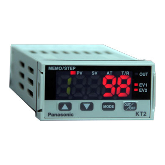
COMMUNICATION INSTRUCTION MANUAL
To prevent accidents arising from the misuse of this controller, please ensure the operator receives this manual.
For this product to which communication function has been added, "1" is entered at the end of the model number.
(For the model number and basic operation, refer to the instruction manual for KT2.)
Warning
Turn the power supply to the instrument off before wiring or checking.
Working or touching the terminal with the power switched on may result in severe injury or
death due to Electric Shock.
1. Setup of the KT2
Set the items "Communication protocol selection", "Instrument number setting", "Communication speed
selection" after the "Sensor correction setting" in Auxiliary function setting mode 1.
To enter Auxiliary function setting mode 1, press the
key.
Display
2. Terminal arrangement
(Fig. 2-1)
TEMPERATURE CONTROLLER
key for 3 seconds while holding down the
Name, Functions, Setting range
Communication protocol selection
• Selects the communication protocol.
•
: Unavailable
: Modbus ASCII mode
: Modbus RTU mode
Instrument number setting
• Sets the instrument number individually to each instrument
when communicating by connecting plural instruments in
serial communication.
• Setting range: 0 to 95 (However, number of connectable units:
Communication speed selection
• Selects a communication speed to be equal to the speed
of the host computer.
•
: 2400bps
: 4800bps
: 9600bps
: 19200bps
• TC
• RTD
• DC
• OUT1 : Control output or Heating output
• POWER SUPPLY: Power terminals
• EV1/OUT2: Event output 1 or Cooling output
• EV2
• DI
• RS-485: Serial communication terminals
1
No. KTC3E5 2013.05
Default value
Modbus ASCII mode
0
Max. 31 units)
9600bps
: Thermocouple input terminals
: RTD input terminals
: DC current, DC voltage input terminals
For DC current input type, connect 50
shunt resistor (sold separately) between
input terminals.
(Heating/Cooling control option) terminals
(Heating/Cooling control option) terminals
: Event output 2 terminals
: DI (Digital input) terminals
Three DI functions: SV1/SV2 external
selection function, OUT/OFF (RUN/STOP)
external selection and Timer function
KT2
Advertisement
Table of Contents

Related Manuals for Panasonic KT2


Summary of Contents for Panasonic KT2
- Page 1 To prevent accidents arising from the misuse of this controller, please ensure the operator receives this manual. For this product to which communication function has been added, “1” is entered at the end of the model number. (For the model number and basic operation, refer to the instruction manual for KT2.) Warning Turn the power supply to the instrument off before wiring or checking.
-
Page 2: System Configuration
3. System configuration RS-485 multi-drop connection communication Host computer RS-485 No.0 No.1 No.2 No.30 (Fig. 3-1) Communication RS-485 Host computer converter RS-232C RS-232C RS-485 No.0 No.1 No.30 (Fig. 3-2) RS-485 No.0 No.1 No.2 No.30 (Fig. 3-3) 4. Wiring When using a communication converter •... - Page 3 Do not connect terminator with the communication line because each KT2 has built-in pull-up and pull-down resistors instead of a terminator. If there is a large distance between the PLC and the KT2, connect the terminator on the PLC side. (Connect a terminator of 120 or more resistance.)
-
Page 4: Communication Procedure
5. Communication procedure Communication starts with command transmission from the host computer (hereafter Master) and ends with the response of the KT2 (hereafter Slave). • Response with data Master Slave When the master sends the reading command, the slave Command... - Page 5 (2) Slave address Slave address is an individual instrument number on the slave side and is set within the range 00H to 5FH (0 to 95). The master identifies slaves by the slave address of the requested message. The slave informs the master which slave is responding to the master by placing its own address in the response message.
- Page 6 • A response message from the slave in exception (error) status (When data item is mistaken) The function code MSB is set to 1 for the response message in exception (error) status [83H (38H 33H)]. If an exception code [02H (30H 32H): Non-existent data address] is returned, the error can be determined by reading this code.
- Page 7 6.4 RTU mode 8-bit binary data in command is transmitted as it is. Data format Start bit : 1 bit Data bit : 8 bits Parity : No parity Stop bit : 1 bit Error detection : CRC-16 (Cyclic Redundancy Check) Data interval : 3.5 characters transmission time or less (1) Message configuration...
- Page 8 XOR is calculated with the next data and X. This is assumed as X. Repeat steps Repeat steps up to the last data. Set X as CRC-16 to the end of message in sequence from low order to high order. (6) RTU mode message example Reading (Address 1, PV) •...
- Page 9 • Response message from the slave in exception (error) status (When a value out of the setting range is set) The function code MSB is set to 1 for the response message in exception (error) status (86H). If an exception code (03H: Value out of the setting range) is returned, the error can be determined by reading this code.
- Page 10 03H/06H 001BH: PV filter time constant Set value, Decimal point ignored 03H/06H 001CH: OUT1 (Heating) high limit Set value 03H/06H 001DH: OUT1 (Heating) low limit Set value 03H/06H 001EH: OUT1 (Heating) ON/OFF action Set value, Decimal point ignored hysteresis 001FH: Not used 0020H: Not used 0021H: Not used 0022H: OUT2 (Cooling) ON/OFF action...
- Page 11 0016H: T [–199.9 to 750.0 ] 0017H: N [–320 to 2300 ] 0018H: PL- [0 to 2500 ] 0019H: C (W/Re5-26) [0 to 4200 ] 001AH: Pt100 [–199.9 to 999.9 ] 001BH: JPt100 [–199.9 to 900.0 ] 001CH: Pt100 [–300 to 1500 ] 001DH: JPt100 [–300 to 900 ] 001EH: 4 to 20mA DC [–1999 to 9999]...
-
Page 12: Specifications
Phone: +81-568-33-7861 FAX: +81-568-33-8591 About our sale network, please visit our website. PRINTED IN JAPAN © Panasonic Industrial Devices SUNX Co., Ltd. 2012 Pursuant to the directive 2004/108/EC, article 9(2) Panasonic Electric Works Europe AG Rudolf-Diesel-Ring 2 83607 Holzkirchen, Germany...