Advertisement
Instruction manual
To prevent accidents arising from the misuse of this controller, please ensure the operator receives this manual.
SAFETY PRECAUTIONS
Be sure to read these precautions before using our products.
The safety precautions are classified into categories: "Warning" and "Caution".
Warning : Procedures which may lead to dangerous conditions and cause death or serious injury, if not
carried out properly.
Caution : Procedures which may lead to dang erous conditions and cause superficial to medium injury
or physical damage or may degrade or damage the product, if not carried out properly.
• When using this controller on occasions which serious injury would be expected to occur or when damage is
likely to expand or proliferate, make sure to take safety measures such as installing double safety structures.
• Do not use this controller in an environment with flammable gases, or it may cause explosion.
• Fasten the electric wire with the t erminal screws securely. Imperfect connection m ay cause a bnormal
heating or fumes.
• Use this controller according to the rating and environmental conditions. Otherwise a bnormal heating or
fumes may occur.
• Do not touch the terminals while t he power is supplied to the controller, as this may ca use electric shock.
• Do not disassemble or modify the controller, as this may cause electric shock or fumes.
Caution
• This instrument should be used in accordance with the specifications described in the manual.
If it is not used according to the specifications, it may malfunction or cause fire.
• Be sure to follow the warnings, cautions and notices. Not doing so could cause serious injury or accidents.
• The contents of this instruction manual are subject to change without notice.
• This instrument is designed to be installed in a control panel. If not, measures must be taken to ensure
that the operator cannot touch power terminals or other high voltage sections.
• Be sure to turn the power supplied to the instrument OFF before cleaning this instrument.
• Use a soft, dry cloth when cleaning the instrument.
(Alcohol based substances may cause tarnishing or defacement of the unit)
• As the display section is vulnerable, do not strike or scratch it with a hard object.
• Any unauthorized transfer or copying of this document, in part or in whole, is prohibited.
• Matsushita Electric Works, Ltd. is not liable for any damage or secondary damage(s) incurred as a result
of using this product, including any indirect damage.
• To pull out the inner assembly, release the hooks at the top and bottom of the instrument with thin, hard
tweezers. (If the hooks are released too far, they may break, or IP 66 function could deteriorate.)
Do not pull out the inner assembly except when repairing the instrument.)
1. Model number
1.1 Explanation of model number
A K T 4
(1) Supply voltage ---------------------- 1: 100 to 240V AC, 2: 24V AC/DC
(2) Input type ----------------------------- 1: Multi-input (Thermocouple, RTD, DC current and DC voltage
(3) Control output (OUT1) ------------ 1: Relay contact, 2: Non-contact voltage, 3: DC current
(4) Alarm output ------------------------- 1: A1 output, 2: A1 output + A2 output
Phone: 800.894.0412 - Fax: 888.723.4773 - Web: www.clrwtr.com - Email: info@clrwtr.com
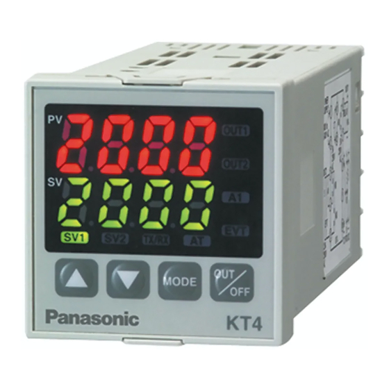
Temperature Controller
1
(1) (2) (3) (4) (5) (6) (7)
(The alarm type and Energized /Deenergized can be selected
by key operation)
(When A2 output is applied, Heating/Cooling control cannot be
added)
Warning
Caution
can be selected by key operation)
KT4
No.KT41E9 2006.08
Advertisement
Table of Contents

Related Manuals for Panasonic KT4 series


Summary of Contents for Panasonic KT4 series
-
Page 1: Model Number
Instruction manual Temperature Controller No.KT41E9 2006.08 To prevent accidents arising from the misuse of this controller, please ensure the operator receives this manual. SAFETY PRECAUTIONS Be sure to read these precautions before using our products. The safety precautions are classified into categories: “Warning” and “Caution”. Warning : Procedures which may lead to dangerous conditions and cause death or serious injury, if not carried out properly. -
Page 2: Name And Functions Of The Sections
(5) Heating/Cooling control (OUT2)-- 0: Not available, 4: Non-contact relay output (6) Heater burnout alarm -------------- 0: Not available, 1: Available (5A), 2: Available (10A), 3: Available (20A), 4: Available (50A) (Heater burnout alarm is not available for the DC current output) (7) Serial communication ------------- 1: Available (The number is indicated only when the serial communication is applied.) 1.2 How to read the rated label... - Page 3 3.2 External dimensions (Unit: mm) Screw typ e mounting bracket Gasket A Terminal cover 11.5 101 (*) (*) Terminal cover (AKT4801) (Fig. 3.2-1) 3.3 Panel cutout (Unit: mm) Lateral close mounting +0.5 n x 48-3 n: Number of unit s mounted Caution: If lateral close mounting is used for the controller , IP66 specification may be compromised, and warranties will be invalidated.
- Page 4 • RS-485: Serial communication (Fig. 4-1) Notice • The terminal block of the KT4 Series is designed to be wired from the left side. The lead wire must be inserted from the left side of the terminal, and fastened by the terminal screw.
- Page 5 5. Setup Wire the power terminals only. After the power is turned on, the sensor input character and temperature unit are indicated on the PV display and the input range high limit value is indicated on the SV display for approximately 3 seconds.
- Page 6 ARW setting • Sets ARW (anti-reset windup). • Available only when PID is the control action. • 0 to 100% Relay contact output: 30 seconds OUT1 proportional cycle setting • Sets proportional cycle for OUT1. Non-contact voltage output: 3 seconds •...
- Page 7 1370 SV high limit setting • Sets the SV high limit. • SV low limit to input range high limit value. For DC input, SV low limit to scaling high limit value (The placement of the decimal point follows the selection) –200 SV low limit setting •...
- Page 8 –1999 Scaling low limit setting • Sets scaling low limit value. • Available only for DC input type • Input range low limit value to scaling high limit value (The placement of the decimal point follows the selection) No decimal point Decimal point place selection •...
- Page 9 No alarm action A2 type selection • Selects an A2 type. • Available only when A2 (option) is added • Action selection and default value are the same as those of A1 type selection. Energized A1 action Energized/Deenergized selection • Selects Energized/Deenergized status for A1. •...
- Page 10 After the unit is mounte d to the control panel and wiring is completed, operate the unit following the procedures below. (1) Turn the power supply to the KT4 Series ON. • For approx. 3sec after the power is switched ON, the sensor input character and the temperature unit are indicated on the PV display and input range high limit value is indicated on the SV display.
-
Page 11: Operation Flowchart
7. Operation flowchart Alarm 1 (A1) setting procedure [Numbers (1) to (5) are indicated on the flowchart.] (1) [A1 type]: Select an Alarm 1 type. Outline of operation procedure [If an alarm type except for is selected, items (2) to (5) Operation before running are indicated and they can be set if necessary.] [STEP 1 Initial setting] : Set Input type, Alarm type, Control action, etc. -
Page 12: Action Explanation
8. Action explanation 8.1 OUT1 action Heating (Reverse) action Cooling (Direct) action Proportional band Proportional band Control action SV setting SV setting Relay contact output Cycle action is performed according to deviation Cycle action is performed according to deviation Non-contact 12V DC 0V DC 0/12V DC... - Page 13 Press the keys for approx. 3 seconds. Alarm type Input type (character indication) and range High limit alarm: The alarm action is deviation setting from the SV. The alarm is activated –200 to 1370 : –320 to 2500 –199.9 to 400.0 : –199.9 to 750.0 : if the input value reaches the high limit set value.
- Page 14 8.4 A1 and A2 action High limit alarm Low limit alarm High/Low limits alarm A1 hysteresis A1 hysteresis A1 hysteresis Alarm action A1 set point + A1 set point A1 set point + A1 set point A1 set point A1 set point setting setting setting...
-
Page 15: Pid Auto-Tuning Of This Controller
8.6 Heating/Cooling control action (when setting dead band) Heating P-band Dead band (Cooling P-band) Heating (Cooling Control action action action) SV setting Relay contact output (OUT1) Cycle action is performed according to deviation. Non-contact 12V DC 12/0V DC 0V DC voltage output (OUT1) Cycle action is performed according to deviation. -
Page 16: Specifications
(1) In the case of a large difference between the SV and processing temperature (PV) as the temperature is rising When AT bias is set to 20 , the AT process will fluctuate at the temperature 20 lower than the SV. Temp. - Page 17 : 0 to 5V DC, 1 to 5V DC, 0 to 10V DC Input impedance (100k or more) Allowable input voltage (15V or less) Allowable signal source resistance (100 or less) Control output (OUT1) Relay contact : 1a, Control capacity 3A 250V AC (resistive load) 1A 250V AC (inductive load cosø= 0.4) Electrical life, 100,000 cycles...
- Page 18 Thermocouple and RTD input Input Input range Indication range Control range –199.9 to 400.0 –199.9 to 450.0 –205.0 to 450.0 K,T –199.9 to 750.0 –199.9 to 850.0 –209.0 to 850.0 –199.9 to 850.0 –199.9 to 900.0 –210.0 to 900.0 –200 to 850 –210 to 900 –210 to 900 Pt100...
-
Page 19: Troubleshooting
Heating/Cooling control (OUT2) • OUT2 side Proportional band: 0.0 to 10.0 times OUT1 proportional band (ON/OFF action when set to 0.0) Proportional cycle: 1 to 120 seconds • Overlap band/Dead band setting range Thermocouple, RTD inputs: –100.0 to 100.0 DC current, DC voltage inputs: –1000 to 1000 (The placement of the decimal point follows the selection) •... - Page 20 • Check whether the polarity of thermocouple or compensating lead ] is flashing on the PV wire is correct. display. • Check whether codes (A, B, B) of RTD agree with the instrument input terminals. Ensure that they are wired properly. •...