
Related Manuals for Panasonic PAN9520


Summary of Contents for Panasonic PAN9520
- Page 1 PAN9520 Embedded Wi-Fi Module Module Integration Guide Rev. 1.1 Wireless Connectivity...
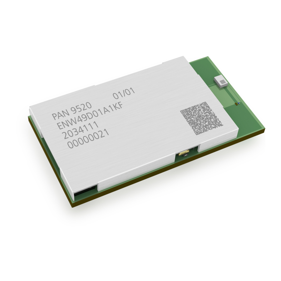
- Page 2 Overview • 36× programmable GPIOs with a rich set of alternative functionalities: The PAN9520 is a 2.4 GHz ISM band Wi-Fi − 2× 12-bit SAR ADCs, up to 20 channels embedded module based on Espressif ESP32-S2, − 2× 8-bit DAC which includes a wireless radio and a MCU for easy −...
- Page 3 Panasonic Industrial Devices Europe GmbH (Panasonic) reserves the right to make changes as required at any time without notification. Please consult the most recently issued Module Integration Guide before initiating or completing a design.
- Page 4 To the maximum extent allowable by Law Panasonic assumes no liability whatsoever including without limitation, indirect, consequential, special, or incidental damages or loss, including without limitation loss of profits, loss of opportunities, business interruption, and loss of data.
-
Page 5: Table Of Contents
Purpose and Audience ......................6 Revision History ......................... 6 Use of Symbols ......................... 6 Related Documents ........................7 Overview .............................. 8 PAN9520 Module ..........................9 Block Diagram ........................... 9 Footprint ..........................10 Placement ..........................11 Power Supply ............................ 13 RF Path .............................. 14 External Antenna ........................ -
Page 6: About This Document
1 About This Document 1.1 Purpose and Audience This Module Integration Guide is intended to support the easy integration of the PAN9520 into a product and to ensure the compliance with regulatory requirements. This guide gives an overview about the hardware design requirements. It is intended for hardware design, application, and Original Equipment Manufacturers (OEM) engineers. -
Page 7: Related Documents
The message Failed to save your data is displayed. Enter the value Product 123. Indicates a key on the keyboard, e.g. F10 . 1.4 Related Documents 8.2 Product For related documents please refer to the Panasonic website Information. Module Integration Guide Rev. 1.1 Page 7 of 44... -
Page 8: Overview
The integrated crystal ensures connection performance over full temperature range and lifetime. Although the PAN9520 is one of the smallest modules on the market, this offers a rich set of peripherals like full-speed USB OTG, SPI, UART, I²C, and many more The PAN9520 combines a high‑performance CPU, high‑sensitivity wireless radio,... -
Page 9: Pan9520 Module
PAN9520 Wi-Fi Module 3 PAN9520 Module 3 PAN9520 Module 3.1 Block Diagram Module Integration Guide Rev. 1.1 Page 9 of 44... -
Page 10: Footprint
PAN9520 Wi-Fi Module 3 PAN9520 Module 3.2 Footprint The outer dimensions have a tolerance of ±0.35 mm. Top View 0.80 mm 1.40 mm 3.30 mm 2.40 mm (Thermal GND) (Thermal GND) (Thermal GND) Antenna Keep out Area (Thermal GND) (Thermal GND) (Thermal GND) 0.60 mm... -
Page 11: Placement
✓ Refer to the recommended pattern when designing a board. The antenna requires a cutout area of 5 mm × 3.3 mm under the PAN9520 module. This “Keep out Area” shall be located in every layer under the module antenna. Note for example the “Keep out Area”... - Page 12 PAN9520 Wi-Fi Module 3 PAN9520 Module Antenna Placement Recommendation Use a ground plane in the area surrounding the module wherever possible. All dimensions are in millimeters. It is recommended to: • Place the module in the center (horizontal) of mother PCB.
-
Page 13: Power Supply
✓ The supply voltage is not exceedingly high or reversed. It should not carry noise and/or spikes. Power Terminals There are three power terminals on the PAN9520. All are connected to the same 3.3 V power net on the module. Although the module could be powered via one terminal only, it is recommended to use all terminals for distributing the currents. -
Page 14: Rf Path
The PAN9520 has a 50 RF pin (SMD pad). Connect an external antenna directly or via a connector (e.g. U.FL) with RF trace to this RF pin. This RF trace shall be matched to 50 ... - Page 15 PAN9520 Wi-Fi Module 5 RF Path A critical point is the transition from the module to the mother PCB. Further simulations of the transition and the RF paths help to determine e.g. the positions of ground vias around the RF pad.
-
Page 16: Regulatory And Certification Information
Limiting the Channel Range and Setting the Country Code The range of channels, on which the PAN9520 can operate, has to be limited according to the location of the module (or end product). The modular approval is only valid, if the OEM applies the needed limitations in the developed software. - Page 17 Country Code Setting with ESP-IDF The Espressif Integrated Development Framwork (ESP-IDF) is the official software development kit (SDK) for the ESP32-S2 IC used on the PAN9520. This contains the function esp_wifi_set_country that can be used for setting the country code and limiting the channel esp_err_t range.
- Page 18 6 Regulatory and Certification Information WIFI_COUNTRY_POLICY_AUTO If the PAN9520 is configured as station, the used country code setting is adapted to the one of the access point (AP), to which the station is connected. Please note that not only the country code itself is changed, but also the channel range.
- Page 19 PAN9520 Wi-Fi Module 6 Regulatory and Certification Information Example 1 (US, Manual Policy) If the module shall be e.g. only operated in the USA, the country code could be set accordingly WIFI_COUNTRY_POLICY_MANUAL and the policy setting can be set to for ensuring that the device cannot operate on prohibited channels in any case.
- Page 20 6.1.1.2 Country Code Setting with ESP32-S2 AT Firmware Instead of developing an embedded software for the PAN9520, an AT firmware provided by Espressif can be used. This is based on the ESP-IDF and is available as source code or precompiled binary.
- Page 21 PAN9520 Wi-Fi Module 6 Regulatory and Certification Information Related Serial Communication Further Readings AT command description: https://docs.espressif.com/projects/esp-at/en/re- lease-v2.1.0.0_esp32s2/AT_Command_Set/Wi-Fi_AT_Commands.html#at- cwcountry-configures-the-wi-fi-country-code 6.1.2 Limiting the Output Power Please note that the power limits documented in this chapter must not be exceeded in the end product to keep the modular approval valid. Examples that fulfill this requirement are documented in the following sections.
- Page 22 Binaries for applying settings that comply with the RED or FCC/IC regulations are provided by Panasonic. The data can be flashed and is used by the hardware if a related partition is reserved in the partition table and the setting CONFIG_ESP32_PHY_INIT_DATA_IN_PARTITION in the project configurations is set to “y”.
- Page 23 PAN9520 Wi-Fi Module 6 Regulatory and Certification Information Example Process Configuring/Editing “phy init data” Defining six Power Values Beginning with the first step of the example configuration process, six power values are defined. They are stored in bytes “52” to “57” (“0x34” to “0x39”) of the binary data and are called txpwr_qdb_0 to txpwr_qdb_5.
- Page 24 PAN9520 Wi-Fi Module 6 Regulatory and Certification Information Values of “TX Power Limit” Name Power (in dBm) depending on defined Values Resulting Power FCC/IC 14 dBm 18 dBm TX Power Limit 0 txpwr_qdb_0 / 4 16 dBm 16 dBm TX Power Limit 1 txpwr_qdb_1 / 4 15 dBm...
- Page 25 PAN9520 Wi-Fi Module 6 Regulatory and Certification Information Configurations txpwr_qdb Index Name Byte Affected Data Resulting Power Position Rate/MCS FCC/IC FCC/IC Binary 11g: 6 Mbit/s & 9 Mbit/s 16 dBm 16 dBm txpwr_index_0 0x01 0x01 (0x3A) 11n: MCS 0 11g: 12 Mbit/s 16 dBm 16 dBm...
- Page 26 PAN9520 Wi-Fi Module 6 Regulatory and Certification Information Each of these bytes is separated into two nibbles: bit[3:0] (low nibble) and bit[7:4] (high nibble). The low nibble configures the limit for standard 802.11g and standard 802.11n. The high nibble configures the limit for standard 802.11b.
- Page 27 Enabling the Usage of a “Phy Init Data” Binary Per default the PAN9520 will use the “phy init data” defined by the source code. If a binary file shall be used, a setting must be applied in the project configuration before the project is compiled.
- Page 28 6 Regulatory and Certification Information 2. Click Component config > PHY to apply the setting. ➔ Now the PAN9520 use the “phy init data” binary. ➔ The default partition table will include a corresponding partition at address “0x8000”, to which the binary must be flashed.
- Page 29 Editing “Phy Init Data” in the Source Code 6.1.2.2 Per default, the “phy init data” set defined in the source code is used by the PAN9520. Therefore, adapting this data is also an option to comply with the regulations. The data can be found in [ESP-IDF] >...
- Page 30 PAN9520 Wi-Fi Module 6 Regulatory and Certification Information 0x00, 0x00, 0x00, 0xf4, 0xf8, 0xf8, 0xf0, 0xf0, 0xf0, 0xe0, 0xe0, 0xe0, 0x18, 0x18, 0x18, /* Start of Power Value Definitions */ // byte 44 (byte 52 in binary) // byte 45 (byte 53 in binary)
- Page 31 PAN9520 Wi-Fi Module 6 Regulatory and Certification Information // byte 69 (byte 77 in binary) // byte 70 (byte 78 in binary) // byte 71 (byte 79 in binary) // byte 72 (byte 80 in binary) // byte 73 (byte 81 in binary)
- Page 32 PAN9520 Wi-Fi Module 6 Regulatory and Certification Information static const esp_phy_init_data_t phy_init_data= { { 0x04, 0x05, 0x04, 0x05, 0x05, 0x04, 0x06, 0x06, 0x06, 0x05, 0x06, 0x00, 0x00, 0x00, 0x00, 0x05, 0x09, 0x06, 0x05, 0x03, 0x06, 0x05, 0x00, 0x00, 0x00,...
- Page 33 PAN9520 Wi-Fi Module 6 Regulatory and Certification Information /* Start of Power Value Definitions */ // byte 44 (byte 52 in binary) // byte 45 (byte 53 in binary) // byte 46 (byte 54 in binary) // byte 47 (byte 55 in binary)
- Page 34 PAN9520 Wi-Fi Module 6 Regulatory and Certification Information } }; Module Integration Guide Rev. 1.1 Page 34 of 44...
-
Page 35: General Certification Information
The FCC requires the user to be notified that any changes or modifications made to this device that are not expressly approved by Panasonic Industrial Devices Europe GmbH may void the user's authority to operate the equipment. This equipment has been tested and found to comply with the limits for a Class B digital device, pursuant to Part 15 of the FCC Rules. - Page 36 Antenna Warning The following antenna has to be followed by the OEM: This antenna warning refers to the device with the model number PAN9520. The device is tested with a integrated antenna listed below. When integrated into the OEM’s product, these fixed antennas require installation preventing end users from replacing them with non-approved antennas.
- Page 37 The end customer has to assure that the device has a distance of more than 20 cm from the human body under all circumstances. If the end customer application intends to use the PAN9520 in a distance smaller 20 cm from the human body, SAR evaluation has to be repeated by the OEM.
-
Page 38: Innovation, Science, And Economic Development (Ised) For Canada
The end customer has to assure that the device has a distance of more than 20 cm from the human body under all circumstances. If the end customer application intends to use the PAN9520 in a distance smaller 20 cm from the human body, SAR evaluation has to be repeated by the OEM. - Page 39 Le client final doit s'assurer que l'appareil se trouve en toutes circonstances à une distance de plus de 20 cm du corps humain. Si le client final envisage une application nécessitant d'utiliser le PAN9520 à une distance inférieure à 20 cm du corps humain, alors le FEO doit répéter l'évaluation DAS.
- Page 40 Panasonic IC identifier for this product as well as the IC Notice above. The IC identifier is: IC: 216Q-9520 This IC identifier is valid for the PAN9520 module. In any case, the end product must be labelled on the exterior with: "Contains IC: 216Q-9520”...
-
Page 41: European Conformity According To Red (2014/53/Eu)
• The end product OEM has to re-assess the conformity of the end product to EU regulations, but can use the PAN9520 RED pre-assessment to shorten this procedure. • The RED EU Type Examination Certificate No. T818887N-01 issued by the Notified Body 0682 can be used for the OEM end product conformance assessment. - Page 42 The end customer equipment must meet the actual Safety/Health requirements according to RED. PAN9520 and its model versions in the specified reference design can be used in all countries of the European Economic Area (Member States of the EU, European Free Trade Association States [Iceland, Liechtenstein, Norway]), Monaco, San Marino, Andorra, and Turkey.
-
Page 43: Restricted Use
Panasonic customers using or selling these products for use in such applications do so at their own risk and agree to fully indemnify Panasonic Industrial Devices Europe GmbH for any damages resulting. -
Page 44: Contact Details
PAN9520 Wi-Fi Module 8 Contact Details 8 Contact Details 8.1 Contact Us Please contact your local Panasonic Sales office for details on additional product options and services: For Panasonic Sales assistance in the EU, visit https://eu.industrial.panasonic.com/about-us/contact-us Email: wireless@eu.panasonic.com For Panasonic Sales assistance in North America, visit the Panasonic website “Sales &...