Table of Contents
Advertisement
Quick Links
Advertisement
Table of Contents

Related Manuals for Panasonic PAN9520 ETU


Summary of Contents for Panasonic PAN9520 ETU
- Page 1 PAN9520 ETU Easy‑To‑Use Evaluation Tool User Guide Rev. 1.0 Wireless Connectivity...
- Page 2 PAN9520 ETU Evaluation Tool Overview PAN9520 Characteristics • The PAN9520 ETU is an evaluation board for the Surface Mount Type (SMT): 24 mm × 13 mm × 3.1 mm PAN9520 embedded Wi-Fi module based on the • Tx power: up to 19.5 dBm at IEEE 802.11b ®...
- Page 3 By purchase of any of the products described in this document the customer accepts the document's validity and declares their agreement and understanding of its contents and recommendations. Panasonic Industrial Devices Europe GmbH (Panasonic) reserves the right to make changes as required at any time without notification.
-
Page 4: Table Of Contents
PAN9520 ETU Evaluation Tool Table of Contents About This Document ......................... 5 Purpose and Audience ......................5 Revision History ......................... 5 Use of Symbols ......................... 5 Related Documents ........................6 Overview .............................. 7 PAN9520 ETU ............................8 Block Diagram ........................... 8 Board Overview ......................... -
Page 5: About This Document
This User Guide is intended to give a detailed description of the Easy-To-Use (ETU) evaluation board components and functionalities. It is intended for hardware design, application, and Original Equipment Manufacturers (OEM) engineers. The product is referred to as “the PAN9520 ETU” or “the ETU” within this document. 1.2 Revision History Revision Date... -
Page 6: Related Documents
The message Failed to save your data is displayed. Enter the value Product 123. Indicates a key on the keyboard, e.g. F10 . 1.4 Related Documents 4.2 Product For related documents please refer to the Panasonic website Information. User Guide Rev. 1.0 Page 6 of 35... -
Page 7: Overview
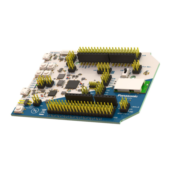
PAN9520 ETU Evaluation Tool 2 Overview 2 Overview The PAN9520 ETU is an evaluation board for the PAN9520 embedded Wi-Fi module, based on the Espressif ESP32-S2. It gives access to the PAN9520 over several different Interfaces like USB, UART, JTAG, and GPIOs. -
Page 8: Pan9520 Etu
PAN9520 ETU Evaluation Tool 3 PAN9520 ETU 3 PAN9520 ETU 3.1 Block Diagram PAN9520 ETU Easy-To-Use Evaluation Board User Interfaces Buttons LEDs FT232 USB to UART1 Debugging/UART USB HUB PAN9520 FT2232 USB to JTAG USB to UART0 Module Native... - Page 9 PAN9520 ETU Evaluation Tool 3 PAN9520 ETU Name Function 1 Module native USB connector Connected to GPIO 19 and GPIO 20, which can be used for USB. 3.11 USB-IO Switch 2 GPIO0/boot button Button SW1 to be used for controlling the Boot Mode at start-up or as general-purpose button in application.
- Page 10 PAN9520 ETU Evaluation Tool 3 PAN9520 ETU Name Function 19 USB IO switch Switch for connecting either periphery like e.g. the GPIO header pins or USB related pull resistors to the native USB traces. 3.11 USB-IO Switch Is connected to the PAN9520’s RF pad.
-
Page 11: Powering Options
PAN9520 ETU Evaluation Tool 3 PAN9520 ETU 3.3 Powering Options The ETU can be powered by the following different sources: (Light red: GND pin is not included on this pin header.) Risk of Damage the Board Components (no. 4 and no. 5) Do not supply 5 V on the 3.3 V pin (“Arduino pin header”... - Page 12 PAN9520 ETU Evaluation Tool 3 PAN9520 ETU Powering Option Description 1 Module native USB The whole board can be powered over the USB connector. connector 2 USB connector The whole board can be powered over the USB connector. The PAN9520 is still powered if the peripherals are deactivated over PER_EN.
-
Page 13: Default Boot Mode
PAN9520 ETU Evaluation Tool 3 PAN9520 ETU Powering Option Description 5 Breakout pins For power supply, the pin 3.3 V and the pin 5 V of the breakout pin headers can be used. If the pin 5V is used, it is recommended to set “5 V Sel.” to “input”. This will add a diode into the supply path, which avoids problems when connecting USB cables. -
Page 14: Breakout Pin Header
For ensuring that the PAN9520 boots the loaded application after powering the board, it is recommended to connect the related pull-up resistor on GPIO0. The caption “Boot Mode” on the PAN9520 ETU indicates the corresponding jumper placement. If the jumper is not placed, after powering the module, the module will enter the Download Mode and an additional reset is needed to start the device in the usual application Boot Mode. - Page 15 PAN9520 ETU Evaluation Tool 3 PAN9520 ETU ETU Pin PAN9520/ESP32-S2 PAN9520 Footprint ESP32-S2 Footprint Pin Name GPIO3 GPIO4 GPIO5 GPIO6 GPIO7 GPIO8 GPIO9 IO10 GPIO10 IO11 GPIO11 IO12 GPIO12 IO13 GPIO13 IO14 GPIO14 IO15 XTAL_32K_P IO16 XTAL_32K_N IO17 DAC_1...
-
Page 16: User Leds
3 PAN9520 ETU 3.6 User LEDs There are three LEDs that can be used for general purposes on the PAN9520 ETU. The LEDs are connected to GPIOs via pin header X3 and hence every LED can be disconnected by unplugging the related jumper. -
Page 17: Arduino Interface
PAN9520 ETU Evaluation Tool 3 PAN9520 ETU SW1/IO0 at Start-Up Pull-Up GPIO0 It is recommended to connect a pull-up resistor on GPIO0 by placing a jumper on the “Boot Mode” pins. This ensures that the PAN9520 boots the loaded application directly after powering the device. - Page 18 PAN9520 ETU Evaluation Tool 3 PAN9520 ETU Arduino Function PAN9520/ESP32-S2 PAN9520 Footprint ESP32-S2 Footprint Pin Name IOREF 3.3 V Ref Voltage nRST Module Reset CHIP PU 3.3 V The maximum output current is 500 mA (if no other 3.3 V pin is used as output).
-
Page 19: Arduino Board/Shield Configuration
PAN9520 ETU Evaluation Tool 3 PAN9520 ETU Arduino Function PAN9520/ESP32-S2 PAN9520 Footprint ESP32-S2 Footprint Pin Name GPIO/UART GPIO18 I7/I8 24/23 (DAC_2)/GPIO17 (RX/TX: depending (DAC_1) on “UART Pin Sel.” setup) 3.9 Arduino Board/Shield Configuration The ETU can be used either as Arduino board or as Arduino shield. The UART communication and the 5 V Power input/output configuration is different between these both modes. -
Page 20: Current Measurement
PAN9520 ETU Evaluation Tool 3 PAN9520 ETU 3.10 Current Measurement Unplug Jumper on X5 To cut the direct power supply to the PAN9520, the Jumper on X5 must be unplugged. Otherwise a current measurement will not work. The ETU provides the feature to measure the current of the PAN9520, independent from the peripheral components. -
Page 21: Usb-Io Switch
PAN9520 ETU Evaluation Tool 3 PAN9520 ETU 3.11 USB-IO Switch GPIO 19 and GPIO 20 can be configured to work as USB interface and are thus connected to the module native USB connector “USB Module”. The connection between the module and the USB connector is permanent. -
Page 22: Camera Interface
3.13 Camera Interface 3.13.1 Pin Assignment The PAN9520 ETU contains a 24-pin FPC connector for operating a camera module via an 8-bit parallel camera interface and SCCB (Serial Camera Control Bus). Placement of the Connector (on the ETU) Pin Assignment... - Page 23 PAN9520 ETU Evaluation Tool 3 PAN9520 ETU Camera Function PAN9520/ESP32-S2 PAN9520 Footprint ESP32-S2 Footprint Pin Name XCLK GPIO10 GPIO6 +3V3 (DOVDD) 1V2-1V8 (DVDD) HREF GPIO5 PWDN GPIO4 VSYNC GPIO3 RST_N (permanent pull-up) SIOC (SCCB clock) GPIO7 2V8-3V3 (AVDD) SIOD (SCCB data)
- Page 24 PAN9520 ETU Evaluation Tool 3 PAN9520 ETU Voltage on 1V2-1V8 (DVDD) Jumper Configuration 1.8 V If none of the described voltage levels is suitable for the used camera: custom voltages in the range from 1.2 V to 3.3 V can be configured by using resistors instead of jumpers for connecting the pins.
- Page 25 PAN9520 ETU Evaluation Tool 3 PAN9520 ETU 3.13.2.2 2V8-3V3 Pin Header Voltage on 2V8-3V3 (AVDD) Jumper Configuration 1.87 V (unusual) 2.8 V 3 V 3.3 V If none of the described voltage levels is suitable for the used camera: custom voltages in the range from 1.87 V to 3.3 V can be configured by using resistors instead of jumpers for...
-
Page 26: Disabling Peripherals
PAN9520 ETU Evaluation Tool 3 PAN9520 ETU The following figure shows the circuit. Pin header “2V8-3V3” is called “X7” in the circuit diagram. The relation between the pin header orientation in the schematic and on the board is also illustrated. -
Page 27: Pan9520 Rf Switch (Spdt) Control
The switch connects the ESP32-S2’s RF pin to either the module’s on-board chip antenna or the RF bottom pad. On the PAN9520 ETU, the bottom pad is connected to the U.FL connector “RF”. The SPDT control lines can be accessed via the pin header “SPDT Ctrl”. -
Page 28: Overview: Interfaces' Pin Assignment
PAN9520 ETU Evaluation Tool 3 PAN9520 ETU 3.16 Overview: Interfaces’ Pin Assignment The following table gives a quick overview of the GPIOs and the interfaces they are used for. Please note that all GPIOs are additionally connected to the GPIO breakout headers. -
Page 29: Software Development
PAN9520 ETU Evaluation Tool 3 PAN9520 ETU Pin Name LEDs Buttons UART0 Camera Arduino JTAG Interface Interface GPIO38 LED3 MTCK (GPIO39) MTCK MTDO (GPIO40) MTDO MTDI (GPIO41) MTDI MTMS (GPIO42) MTMS U0TXD (GPIO43) U0TXD U0RXD U0RXD (GPIO44) GPIO45 Evaluated at start-up (strapping pin) - Page 30 PAN9520 ETU Evaluation Tool 3 PAN9520 ETU 3.17.2 Espressif AT-Software The PAN9520 is a radio certified module. There are conditions on hardware and software which must be met for the modular approval to be valid. For detailed information please refer to “PAN9520 Module Integration Guide”.
- Page 31 Default Settings in the “factory_param” Binary 3.17.3.1 For a convenient usage of the pre-built AT software with the PAN9520 ETU, it is recommended to replace the file factory_param.bin. This configures the default settings for e.g. the pin assignment. On the PAN9520 ETU, the standard UART1 pins (GPIO 17 to 20) are connected to the FT232 USB to UART interface.
- Page 32 PAN9520 ETU Evaluation Tool 3 PAN9520 ETU 4. Copy the bytes (hexadecimal format) FC FC 02 05 40 01 01 0D 45 55 00 00 00 C2 01 00 11 12 14 13. Right-click on position 00 (1) > Paste write (2) to paste the bytes.
- Page 33 PAN9520 ETU Evaluation Tool 3 PAN9520 ETU 3.17.3.2 Flashing the AT Software and adapted Binaries This section gives a short description on how the AT software and the adapted binaries can be flashed. Please note that instead of flashing the combined “factory_WROVER” binary, all files could be downloaded separately.
- Page 34 PAN9520 ETU Evaluation Tool 3 PAN9520 ETU 3. Enter the address 0x0 (2). 4. Enable the option DoNotChgBin (3). 5. Click Start (4) to flash the AT software binary. ➔ The combined AT software binary has been flashed. Overwrite partitions by using the adapted binary files: 6.
-
Page 35: Contact Details
PAN9520 ETU Evaluation Tool 4 Contact Details 4 Contact Details 4.1 Contact Us Please contact your local Panasonic Sales office for details on additional product options and services: For Panasonic Sales assistance in the EU, visit https://eu.industrial.panasonic.com/about-us/contact-us Email: wireless@eu.panasonic.com For Panasonic Sales assistance in North America, visit the Panasonic website “Sales &...