Zip HydroTap G4 Installation And Operating Instructions Manual
B & ba commercial
Hide thumbs
Also See for HydroTap G4:
- User manual (560 pages) ,
- Installation instructions manual (40 pages) ,
- Installation and operating instructions manual (28 pages)

Related Manuals for Zip HydroTap G4


Summary of Contents for Zip HydroTap G4
-
Page 1: Step
Zip HydroTap G4 ® Installation and Operating Instructions B & BA Commercial Affix Model Number Label Here 801530 801530 v3.05 09.20 HT B BA Commercial Instructions Page 1 of 28... -
Page 2: Step
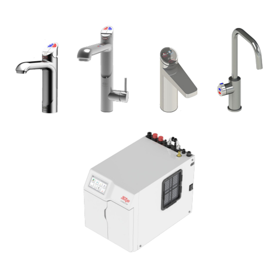
Tap Options The Zip HydroTap G4 appliance series offers a range of interchangeable taps to suit the customer’s needs Classic Tap These three taps are directly compatible with the G4 Command Centre. Arc / Cube Tap Elite Tap The Mixer tap range is an additional series of taps that... -
Page 3: Table Of Contents
Index HydroTap Specifications Installation Checklist ........................4 General Product Features ......................5 Important Safety Instructions ....................... 6 Warnings and Regulatory Information ..................7 Major Components and Accessories ................... 8 Technical Specification ........................ 9 Before Installation and Site Requirements ................... 10 Installation Instructions STEP 1 - Measure and cut all the tap holes before fitting the taps... -
Page 4: Installation Checklist
Installation Checklist Before Installation: Read the instructions and check if there is adequate space to mount all of the components. Note: Not all fittings are supplied with the appliance kit. Isolation valves are not supplied. Check the mains water pressure is between 150 - 700kPa and 200 - 700kPa when a Booster and / or filter softener is fitted Check the water quality to determine if extra filtration will be required. -
Page 5: General Product Features
General Product Features Thank you for purchasing a Zip HydroTap. Please read and follow these instructions carefully to ensure safe operation and trouble-free service. If service is required, please contact your Zip service provider. What is the Zip HydroTap ? The HydroTap Command Centres are under bench drinking water appliances with a dispensing tap mounted on a sink or bench, which may be used for residential or commercial applications. -
Page 6: Important Safety Instructions
Lifting Take care when lifting the Zip HydroTap Command Centre. Some units may exceed safe lifting limits. If you feel this is beyond your personal capabilities, please seek assistance with the lift. The weights of the units are marked on the packaging. -
Page 7: Warnings And Regulatory Information
7. Command Centres must never be located near, or cleaned with water jets. 8. Zip HydroTaps are not to be exposed to the elements of nature 9. Due to the process of continuous improvement, Zip Heaters reserves the right to change details mentioned in this manual, without notice. -
Page 8: Major Components And Accessories
Major Components and Accessories Parts supplied Description Accessories Description 1 x Tap option HydroTap Booster with hoses Water System with (Classic tap shown) connection hoses 1 x HydroTap Command Centre Softener cartridge with water filter and head assembly 1 x Mains water connection hose Font Kit for Arc &... -
Page 9: Technical Specification
Technical Specifications Commercial Models Boiling Only Boiling Ambient 3-in-1* and All-In-One BAHA 4-in-1* and All-In-One Disabled lever controls (optional accessory) Note: Cup measurement =167ml Products covered by these instructions: Capacity Power Power Boost Unit Dimensions **Dry H/T Tap Boost Boiling outlet's Rating Rating... -
Page 10: Before Installation And Site Requirements
• For Zip HydroTap 160 models, a 220-240V AC, 10A power outlet will be required. For Zip HydroTap 240 models, two 220-240V AC, 10A power outlets will be required (one power outlet for the Zip HydroTap and the other for the Booster heater). -
Page 11: Refer To The Tap Installation Instruction Book 803341
Section 1 Tap Installation Refer to the Tap installation instruction book 803341. Section 2 Ventilation All Models IMPORTANT: Proper air circulation must be provided. Allow a clearance envelope of 50mm either side, and 200mm above the Command Centre. The system will operate correctly only if the recom- mended clearances are provided. -
Page 12: Product Description
Product Description The Booster is a compact electronically controlled auxiliary water heater. It is intended to provide pre heating of water before it enters the Zip HydroTap G4 boiling tank. The Booster is supplied as standard equipment with all 240 cup models. -
Page 13: Installation Procedure
Booster Installation Installation Procedure Site requirements • The appliance must only be installed in a frost-free area. Never expose appliance to frost. • The appliance is designed for wall mounted Installation and must to be installed with water connectors facing upwards. •... -
Page 14: Braided Hose Connections
‘Bypass Out’ fitting to the water inlet of the booster unit (marked blue) and from the outlet of the booster unit (marked red) to the ‘Bypass IN’ fitting on the Zip HydroTap unit. Avoid exerting any mechanical pressure on the appliance. This can be achieved by applying a spanner on the flats of the inlet and outlet connections when tightening the braided hose connectors. -
Page 15: Section 4 - Filter / Softener Installation
Section 4 Filter / Softener installation An external filter / softener may be fitted to reduce the incidence of scale build up in the hot tank or may be at the customer’s request. Mounting the filter head • Choose a suitable location, (cupboard back or side wall) within the reach of the braided hoses. -
Page 16: Step
The diverter bypass valve allows the user to choose to have the boiling feed water bypass the internal filter and be filtered externally. The diverter valve is located at the rear panel of the Zip HydroTap Command Centre on the filter door side. Check the image below to determine which filter bypass position you need for your product. -
Page 17: Model B160
Installation Instructions Model B160 Note: the hoses the hoses Note: need to have a need to have a constant downward constant downward gradient to the gradient to the Hydrotap to allow all Hydrotap to allow all water to drain back water to drain back into the tanks. -
Page 18: Model B240
Installation Instructions Model B240 Booster Note: the hoses the hoses Note: need to have a need to have a constant downward constant downward gradient to the gradient to the Hydrotap to allow all Hydrotap to allow all water to drain back water to drain back into the tanks. -
Page 19: Model Ba160
Installation Instructions Model BA160 Note: the hoses the hoses Note: need to have a need to have a constant downward constant downward gradient to the gradient to the Hydrotap to allow all Hydrotap to allow all water to drain back water to drain back into the tanks. -
Page 20: Model Ba240
Installation Instructions Model BA240 Note: Note: the hoses the hoses Booster need to have a need to have a constant downward constant downward gradient to the gradient to the Hydrotap to allow all Hydrotap to allow all water to drain back water to drain back into the tanks. -
Page 21: Model Bha160 & Baha160
Installation Instructions Model BHA160 3-In-1 and BAHA160 4-in-1 Note: the hoses the hoses Note: HydroTap need to have a need to have a Mixer constant downward constant downward Connections gradient to the gradient to the Hydrotap to allow all Hydrotap to allow all water to drain back water to drain back into the tanks. -
Page 22: Model Bha240 & Baha240
Installation Instructions Model BHA240 3-In-1 and BAHA240 4-in-1 HydroTap Note: Note: the hoses the hoses Booster Mixer need to have a need to have a Connections constant downward constant downward gradient to the gradient to the Hydrotap to allow all Hydrotap to allow all water to drain back water to drain back... -
Page 23: Model Bha160 & Baha160 All-In-One
Installation Instructions Model BHA and BAHA160 All-In-One (Mains) HydroTap Note: the hoses the hoses Note: Mixer need to have a need to have a Connections constant downward constant downward gradient to the gradient to the Hydrotap to allow all Hydrotap to allow all water to drain back water to drain back into the tanks. -
Page 24: Section 6 - Commissioning
Section 6 Commissioning Do not commission your HydroTap until it is ready to be used! The HydroTap is designed to be installed, commissioned and used within 48 hours. If your HydroTap is left idle before use, a filter change and sanitisation may be required. -
Page 25: Boiling Calibration
Commissioning 1. Turn the stop cock ON 2. Press [Start] [Stop] buttons to start and stop the filter flush. 3. Allow at least 10 litres of water to flush through the filter. 4. Once the filter flush is finished, turn the stop cock OFF then press [Stop] to end filter flush mode. -
Page 26: Safety Sensor Calibration
Safety Sensor Calibration Safety Sensor Calibration Light intensity varies from site to site, therefore it is recommended that a re-calibration be performed at the time of the installation. All direct natural sun light must be shaded from the HydroTap, during the calibration. This can be achieved by closing any nearby curtains, blinds, or by shielding the HydroTap with a dark cloth. -
Page 27: Troubleshooting
Internal fault Call Zip Service Call an electrician, a plumber, or Zip service provider for assistance, service, spare parts or enquiries. End of Life Disposal In order to help preserve our environment we ask that you dispose of this product correctly. Please contact your local city council for collection centre details. -
Page 28: Contact Details
Zip Water (Aust) Pty Ltd ABN 46 000 578 727 67-77 Allingham St, Condell Park NSW 2200 Postal: Locked Bag 80, Bankstown 1885 Australia zipwater.com | (+612) 9796 3100 | 1800 ZIP TAP (1800 947 827) WMKA00099 AS 3498 The terms “Zip” and “HydroTap” are registered trade marks of Zip Water (Aust) Pty Ltd.