Advertisement
Quick Links
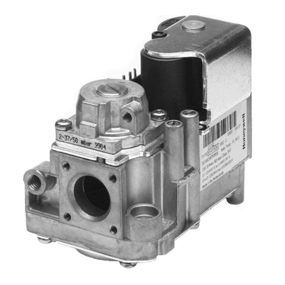
GAS CONTROLS WITH INTEGRATED 1:1 GAS/AIR REGULATOR FOR
APPLICATION
The VK41..V(B)/VK81..V(B) series gas controls with 1:1 gas/
air regulator have been developed for application in domestic
appliances with premix burners and automatic ignition.
For this system, the VK41..V series gas controls have been
designed to have the S4565 series ignition control attached
directly onto the valve.
The combined system then provides programmed safe light
up, flame supervision and regulation of gas flow to the main
burner of the appliance.
The VK41..V(B)/VK81..V(B) series can as well be used as
stand alone in direct burner applications. The plug (order
number 45.900.441-) with integrated rectifier circuit then has
to be used.
The VK41..V(B)/VK81..V(B) series are used in a system
context in conjunction with fan control and a direct spark
ignition (DSI) control.
The VK41..V(B)/VK81..V(B) series are approved in
accordance with european standards.
DESCRIPTION
VK41..V(B)/VK81..V(B) gas controls perform all the functions
required to safely regulate gas flow to the main burner of
domestic central heating equipment, warm air furnaces, back
boilers and water heaters.
VK41..V(B)/VK81..V(B) SERIES
COMBINED VALVE AND IGNITION SYSTEM
1
VK41..V(B)/VK81..V(B) gas controls hold a first electric on/
off direct operator for opening the safety valve of class B
according to EN161 and a second electric on/off servo
operator of class B or C to EN 161.
The pressure regulator is in accordance with class B
requirement of EN 88.
VK41..V/VK81..V gas controls can handle the three gas
families, manufactured gas, natural gas and LP gas.
VK41..VB/VK81..VB gas controls can handle second family
gas only.
SPECIFICATIONS
Models
VK41.0 series: line voltage gas control with pilot burner
connection, two automatic shut off valves and
pilot burner connection for direct spark
ignition (DSI) or hot surface ignition (HSI)
applications,
VK41.5 series: line voltage gas control without pilot burner
connection, two automatic shut off valves for
direct spark ignition (DSI) or hot surface
ignition (HSI) applications,
VK81.0 series: low voltage gas control with pilot burner
connection, two automatic shut off valves for
direct spark ignition (DSI) or hot surface
ignition (HSI) applications,
VK81.5 series: low voltage gas control without pilot burner
connection, two automatic shut off valves for
direct spark ignition (DSI) or hot surface
ignition (HSI) applications,
Suffix letter
V: fast opening, with integrated 1 : 1 gas/air regulation
VB: fast opening, with integrated 1 : 1 gas/air regulation
High capacity
Main gas connection
See table 1, table 2 and table 3.
3
1
/
" and
/
" straight or elbow flanges are according to the
8
2
torsion and bending stress of EN 126 group 2
1
Connections with G
/
" or G
2
nuts according to ISO 228-1 in combination with applicable
sealing(s) withstand the torsion and bending stress of EN
126 group 1
Side outlet (optional) and end outlet (flanged version) can be
fitted direct to a burner manifold.
End outlet or side outlet Quick connection for Mini-Venturi
Pilot gas connection (where applicable)
Standard at end outlet: M8 x 1 for 4 mm outer diameter
tubing.
INSTRUCTION SHEET
3
/
" external thread fitted with
4
EN1R-9134 0503R20-NE
Advertisement

Related Manuals for Honeywell VK41 V Series


Summary of Contents for Honeywell VK41 V Series
- Page 1 VK41..V(B)/VK81..V(B) SERIES GAS CONTROLS WITH INTEGRATED 1:1 GAS/AIR REGULATOR FOR COMBINED VALVE AND IGNITION SYSTEM INSTRUCTION SHEET VK41..V(B)/VK81..V(B) gas controls hold a first electric on/ off direct operator for opening the safety valve of class B according to EN161 and a second electric on/off servo operator of class B or C to EN 161.
- Page 2 Side outlet M5 x 0,8 (3) 94,8 6 mm full thread 68,3 Pressure tab Cap screw/offset adjustment 84,5 Hole 2.6 mm to connect ignition control Side outlet (optional) Air pressure connection Pilot outlet M8 x 1-6H for 4 mm tubing 36,7 36,7 Outlet...
-
Page 3: Electrical Data
VK4110/VK4115 Class B Class C VK8110/VK8115 Inlet End outlet Side outlet Body length (mm) VK4120/VK4125 Class B Class B VK8120/VK8125 Flanged Flanged Timing Flanged Flanged ≤ 1 s Closing time: Internal ” Flanged Opening time: see table ISO 7-1 Internal ”... -
Page 4: Installation
Mounting of rectifier plug Main gas connection See fig. 2. Gas controls with internal thread Mounting screw of rectifier plug • Take care that dirt cannot enter the gas control during Torque: 40 Ncm max. handling. • Use a sound taper fitting with thread according to ISO 7-1 or a piece of new, properly reamed pipe, free from swarf. - Page 5 Gas controls with external thread connection With ” nut and “O”-ring (see fig 7.) Pipe diameter: 15 mm WARNING Nut: drawing: ........45.006.583-003 “O”-ring size: ∅14.3 x ∅2.4 mm Fastening torque flat sealing ring only applicable for drawing ........45.001.528-048 Fastening torque: maximum 50 Nm type Klingersil C4324 minimum 10 Nm Pipe end construction: see fig.: 10.
-
Page 6: Electrical Connections
CAUTION Keep soap and water solution away from electrical + 0.2 23.4 - 0.2 connections. Electrical connections IMPORTANT Fig. 11. Pipe (dia 15 mm) for flat sealing ring connection Disconnect power supply to prevent electrical shock and/or equipment damage. Wiring must be in accordance with local regulations. The appliance manufacturer’s instructions should always be followed. -
Page 7: Maintenance And Service
ADJUSTMENTS CHECKOUT • After any adjustment check pressure taps and gas WARNING connections with an approved leak detection fluid for gas leakage. Adjustments must be made by qualified persons only. • After any adjustment set appliance in operation and If the appliance manufacturer supplies checkout and/ observe a complete cycle to ensure that all burner or service and maintenance instructions carefully components function correctly. - Page 8 Home and Building Control Combustion Control Center Europe Honeywell BV Phileas Foggstraat 7 7821 AJ Emmen The Netherlands Tel.: +31 (-)591 695911 Fax: +31 (-) 591 695200 http://europe.hbc.honeywell.com EN1R-9134 0503R20-NE...