Advertisement
Quick Links
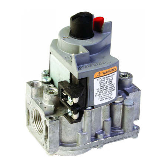
These continuous pilot gas controls are used in gas-fired
appliances with capacities up to 200 cu ft/hour at 1 in. wc
pressure drop [5.7 cu m/hour at 0.25 kPa] on natural gas.
They include a manual valve, safety shutoff, single auto-
matic operators, and a pressure regulator. See Table 3 for
temperature ranges and regulator types.
Size
(Inlet x Outlet)
1/2 x 1/2
1/2 x 3/4
3/4 x 3/4
a
Capacity based on 1000 Btu/cu ft, 0.64 specific gravity natural gas at 1 in. wc pressure drop [37.3 MJ/cu m, 0.64 specific
gravity natural gas at 0.25 kPa pressure drop.
Use conversion factors in Table 2 to convert capacities
for other gasses.
TABLE 2—GAS CAPACITY
CONVERSION FACTORS.
Specific
Gas
Gravity
Manufactured
Mixed
Propane
Model Number
VR8300A
VR8300C
VR8300H
VR8300K
VR8300M
VR8300P
VR8301
Continuous Pilot Combination
Application
TABLE 1: CAPACITY OF VR8300/VR8301
Capacity (at 1 in. wc
a
pressure drop)
180 cu ft/hr
[5.1 cu m/hr]
190 cu ft/hr
[5.4 cu m/hr]
200 cu ft/hr
[5.7 cu m/hr]
Multiply Listed
Capacity By
0.60
0.516
0.70
0.765
1.53
1.62
TABLE 3—TEMPERATURE RANGES AND REGULATOR TYPES.
Ambient Temperature Range
0° F to 175° F [-18° C to +79° C]
0° F to 175° F [-18° C to +79° C]
0° F to 175° F [-18° C to +79° C]
-40° F to 175° F [-40° C to +79° C]
-40° F to 175° F [-40° C to +79° C]
-40° F to 175° F [-40° C to +79° C]
0° F to 175° F [-18° C to 79° C]
J.H. • Rev. 9-94 • ©Honeywell Inc. 1994 • Form Number 69-0624—2
VR8300/VR8301
BODY PATTERN: Straight-through body pattern.
INLET X OUTLET SIZES AVAILABLE: 1/2 x 1/2 in., 1/2 x
3/4 in., and 3/4 x 3/4 in. (factory-installed inlet flange).
ADAPTERS: Adapters available for 1/2 and 3/4 inch straight
and angle connections. Refer to Table 4.
ELECTRICAL RATINGS:
Voltage and Frequency: 24 Vac, 50/60 Hz.
Current Draw: 0.70A.
CAPACITY: See Table 1.
Minimum
Regulated Capacity
30 cu ft/hr
[0.8 cu m/hr]
30 cu ft/hr
[0.8 cu m/hr]
30 cu ft/hr
[0.8 cu m/hr]
TABLE 4—FLANGE PART NUMBERS.
Inlet/Outlet
Flange
Pipe Size
Type
1/2 inch NPT
Straight 394599-6
Elbow
3/4 inch NPT
Straight 394599-4
Elbow
NOTE: Flange kits include one flange with attached O-ring
and fan mounting screw.
1
Gas Control
Maximum
Regulated Capacity
225 cu ft/hr
[6.4 cu m/hr]
290 cu ft/hr
[8.2 cu m/hr]
300 cu ft/hr
[8.5 cu m/hr]
Part Number
Without
Hex
Wrench
393690-16
394599-3
393690-13
393690-14
394599-5
393690-15
Regulator Type
Standard-opening
Step-opening
Slow-opening
Slow-opening
Standard-opening
Step-opening
Standard-opening
With
Hex
Wrench
69-0624—2
Advertisement

Related Manuals for Honeywell VR8300


Summary of Contents for Honeywell VR8300
- Page 1 -40° F to 175° F [-40° C to +79° C] Standard-opening VR8300P -40° F to 175° F [-40° C to +79° C] Step-opening VR8301 0° F to 175° F [-18° C to 79° C] Standard-opening J.H. • Rev. 9-94 • ©Honeywell Inc. 1994 • Form Number 69-0624—2 69-0624—2...
-
Page 2: Installation
To convert a gas control from natural gas to LP gas or from them could damage the product or cause a hazardous LP gas to natural gas, contact your Honeywell representative. condition. Standard- or slow-opening gas controls are converted from 2. - Page 3 TABLE 5—NPT PIPE THREAD LENGTH IN IN. Fig. 1—Install flange to gas control. Maximum Depth Pipe Can Be Pipe Thread Pipe Inserted Into Size This Amount Control 9/16 13/16 9/64 INCH HEX SCREWS (4) 4. Apply a moderate amount of good quality pipe com- pound (do not use Teflon tape) to pipe only, leaving two end threads bare.
- Page 4 Fig. 4—Top view of gas control. Fig. 6—Always use new compression fitting. PRESSURE REGULATOR WIRING ADJUSTMENT TERMINALS (3) (UNDER CAP SCREW) GAS CONTROL INLET OUTLET PRESSURE TAP TIGHTEN NUT ONE TURN PRESSURE BEYOND FINGER TIGHT BURNER INLET OUTLET FITTING BREAKS OFF AND CLINCHES PILOT OUTLET TUBING AS NUT IS TIGHTENED M3076A...
- Page 5 3. Adjust thermostat heat anticipator to 0.70 rating stamped on valve operator. Fig. 7—Installing thermocouple to the power unit. Fig. 8—VR8300 wiring connections for 24 volt control. THERMOCOUPLE LEAD 24 V THERMOSTAT HIGH LIMIT CONTROLLER (HOT) OPTIONAL CONVENIENCE TH/TR TERMINALS VR8300 TERMINALS POWER SUPPLY.
-
Page 6: Start-Up And Checkout
TABLE 7—MAXIMUM LENGTH OF SUPPLEMENTARY LIMIT LEADWIRES WHEN USING Q309A THERMOCOUPLE. Maximum Leadwire Length x 2 (Wires) Thermocouple Length Awg No. 14 Awg No. 16 Awg No. 18 Inches Meters Inches Meters Inches Meters Inches Meters DO NOT USE. Start-up and Checkout CAUTION Stand clear while lighting main burner to prevent WARNING... - Page 7 LIGHT MAIN BURNER Standard-Opening and Slow-Opening Pressure Follow the appliance manufacturer instructions or set the Regulator thermostat setting above room temperature to call for heat. 1. The gas control outlet pressure should match the mani- fold pressure listed on the appliance nameplate. 2.
-
Page 8: Maintenance
TABLE 8—PRESSURE REGULATOR SPECIFICATION PRESSURES IN IN. WC. Outlet Pressure Nominal Factory Setting Setting Range Nominal Inlet Pressure Nominal Inlet Type of Gas Pressure Range Model Step Full Rate Step Full Rate Natural 5.0 - 7.0 — — 3.0 - 5.0 Standard, Slow opening 12.0 - 14.0... - Page 9 Service 3. Use an ac voltmeter to measure the voltage across terminals TH and TR or MV/PV and MV. If: a. No voltage is present, check the control circuit for WARNING proper operation. b. 24 Vac is present, but first operator did not click open, FIRE OR EXPLOSION HAZARD CAN check for excessive inlet gas pressure.
- Page 10 Home and Building Control Home and Building Control Helping You Control Your World Honeywell Inc. Honeywell Limited—Honeywell Limitée 1985 Douglas Drive North 740 Ellesmere Road Golden Valley, MN 55422 Scarborough, Ontario M1P 2V9 QUALITY IS KEY 69-0624—2...