Advertisement
Quick Links
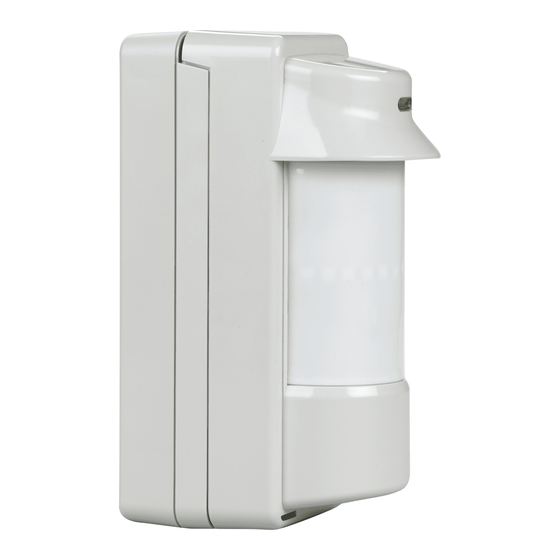
5800-OD Wireless Outdoor Motion Sensor – Installation Instructions
GENERAL INFORMATION
The Honeywell 5800-OD Wireless Outdoor Motion Sensor
(referred to as the 5800-OD) combines the convenience of wireless
technology with a full featured outdoor PIR motion sensor. The
major features are highlighted below:
Immunity to bright light
disturbances from headlights,
sunlight, and other bright
light sources.
Discriminates both large and
small animals to reduce false
alarms.
Battery saving circuit allows
for a 5 or 120 second period of
inactivity before being
reactivated.
SPECIFICATIONS
Passive Infrared
Detection Method
Initial Warm Up
~ 2 minutes
Mounting Height
0.8 - 1.2m (2.7 - 4ft) wall or pole
INSTALLATION (refer to the Component Identification Diagram on page 5)
1
Select the Mounting Position
Orient the detector
Avoid strong sunlight into the sensor's field.
so that intrusion
Avoid moving or swaying trees and bushes.
passes across the
detection field, not
into the sensor.
2
Prepare the Sensor for Mounting
1.
Loosen the Captive Lock
Screw and remove the
Cover.
3
Install / Replace the Battery
IMPORTANT:
Use only lithium batteries.
Use four (4) lithium 1.5VDC AA cells. (Energizer L91 or
equivalent.)
Observe polarity.
Mark the date of replacement on the batteries.
PLEASE GO TO PAGE 6 FOR FCC / IC STATEMENTS
Very low current draw.
Selectable detector
range and angle.
Tamper detection.
2.
Remove the four (4) screws fastening the Detector
to the Back Box.
Range
Pattern
Sensitivity
Detection Speed
Operating Voltage
Current
Battery Saving Timer
Alarm Period
LED Indicator
Weatherproof
Operating Temperature
Humidity
Accessories (included)
Allow 110mm (4.4")
above the sensor to
enable opening the
cover.
Choose an installation
height of 0.8m to 1.2m
(2.7 to 4ft).
3.
Remove Detector from the Back Box.
1.
If necessary, loosen the
Captive Lock Screw and lift
Cover off. Then, remove 4
screws that secure the
Detector to the Back Box.
2.
Observe the proper polarity
and replace the batteries.
Ensure positive side of
battery is pointing away from
the springs.
3.
For reference, mark the date of
replacement on the batteries.
Adjustable up to 12m (40ft)
90° pattern consisting of 13 zones. This
pattern can be adjusted in 15° incre-
ments from center up to 45°.
2.0° C at 0.6m/s (3.6° F at 2.0ft/s)
0.3 - 1.5m/s (1 - 5ft/s)
6 VDC (uses 4 lithium 1.5VDC AA cells)
3mA max (during walk test) 10uA
(standby)
Adjustable 120sec or 5sec
~ 2.5 seconds
Enabled during a walk test.
Disabled for normal operation.
IP54 compliance
– 20 to + 50 ° C (– 4 to +122° F)
95% Max
Pole mounting kit, screw kit, detection
masking strips.
Ensure the sensor can be
mounted on a perpendicular
wall or pole that would make
its detection pattern parallel
to the ground.
Parallel
Advertisement

Related Manuals for Honeywell 5800-OD


Summary of Contents for Honeywell 5800-OD
- Page 1 5800-OD Wireless Outdoor Motion Sensor – Installation Instructions GENERAL INFORMATION The Honeywell 5800-OD Wireless Outdoor Motion Sensor (referred to as the 5800-OD) combines the convenience of wireless Range Adjustable up to 12m (40ft) technology with a full featured outdoor PIR motion sensor. The Pattern 90°...
-
Page 2: Mount The Sensor
5800-OD Wireless Outdoor Motion Sensor – Installation Instructions Mount the Sensor WALL MOUNTING Install the Back Box on the Insert the batteries (see Perform Settings & Adjustments. wall with the two T4 x 20 Install/Replace the Battery), Perform a Walk Test. - Page 3 5800-OD Wireless Outdoor Motion Sensor – Installation Instructions Press and slide the Detection Length Adjustment Switch to the desired position. MAX DETECTION LENGTH POSITION STANDARD ENVIRONMENTAL 02.0m (6.7ft) 1.5 - 2.5m (5 - 8ft) 05.0m (16.7ft) 04 - 5.5m (13 - 18ft) 08.0m (26.7ft)
-
Page 4: Perform A Walk Test
5800-OD Wireless Outdoor Motion Sensor – Installation Instructions SET THE SENSITIVITY SET THE DIP SWITCHES Set the Sensitivity Select Switch to the desired Set switch 2 for the desired Set switch 3 for the desired Pulse Count sensitivity. Battery Saving Timer (selectable for 2 or 4). -
Page 5: Component Identification
5800-OD Wireless Outdoor Motion Sensor – Installation Instructions TROUBLESHOOTING SYMPTOM CAUSE REMEDY Alarms when no one is walking Sensor is not perpendicular to ground. Remount and align sensor so the detection area is parallel to through the detection area. the ground. -
Page 6: Fcc / Ic Statement
Tel: +44(0)1698 738200 Email: UK64Sales@Honeywell. © 2008 Honeywell International Inc. Honeywell is a registered trademark of Honeywell International Inc. All other trademarks are the properties of their respective owners. All rights reserved. Please contact your local authorized Honeywell representative for product warranty information.