Makita DHR263 Technical Information
Hide thumbs
Also See for DHR263:
- Instruction manual (85 pages) ,
- Instruction manual (37 pages) ,
- Instruction manual (37 pages)
Advertisement
Quick Links
T
ECHNICAL INFORMATION
Model No.
Description
C
ONCEPT AND MAIN APPLICATIONS
Models DHR263/ DHR264 are 26mm cordless combination hammers
based on Models BHR262 and BHR262T, and powered by
two 18V Li-ion batteries in series.
Their main features are:
• Compact design
• 3 operation modes (rotation only/ rotation with hammering/ hammering only)
• Battery capacity warning lamp
• XPT (eXtreme Protection Technology)
Models
Chuck system
DHR263
Normal chuck
DHR264
Quick change chuck
S
pecification
Specification
Voltage: V
Capacity: Ah
Battery
Energy capacity: Wh
Cell
Charging time (approx.): min.
Max output: W
No load speed: min.
¹= rpm
ˉ
Impacts per minute: min.
Chuck type
Capacity of Quick change chuck: mm (")
Concrete
Capacity: mm (")
Steel
Wood
Operation mode
Variable speed control
Reversing switch
Torque limiter
LED job light
Weight according to
EPTA-Procedure 01/2003*
*1 Round shank bits can also be used by replacing the factory-mounted chuck with Quick change drill chuck (keyless).
*2 With side grip, two batteries BL1830, BL1840 or BL1850
DHR263/ DHR264
26mm (1") Cordless Combination Hammers
Model
¹
ˉ
TCT bit
Core bit
Diamond core bit
3 modes (Rotation only/ Rotation with hammering/ Hammering only)
: kg (lbs)
2
DHR263
1.5, 2.0, 3.0, 4.0, 5.0
27x2, 36x2, 54x2, 72x2, 90x2
15x2, 24x2, 22x2, 36x2, 45x2 with DC18RC
Adapted for SDS-PLUS bits
N/A
65 (2-9/16)
4.6 (10.1)
OFFICIAL USE
for ASC & Sales Shop
PRODUCT
W
L
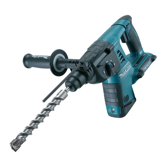
The image above is model DHR263.
Dimensions: mm (")
Model No.
DHR263
Length (L)
350 (13-3/4) 374 (14-3/4)
Width (W)
116 (4-9/16)
Height (H)
232 (9-1/8)
DHR264
36 (18x2)
Li-ion
600
0 - 1,250
0 - 5,000
Adapted for SDS-PLUS bits
and Round shank bits*
1.5 (1/16) - 13 (1/2)
26 (1)
54 (2-1/8)
13 (1/2)
32 (1-1/4)
Yes
Yes
Yes
Yes
4.7 (10.3)
P 1/ 22
H
DHR264
1
Advertisement

Related Manuals for Makita DHR263


Summary of Contents for Makita DHR263
- Page 1 DHR263/ DHR264 Description 26mm (1") Cordless Combination Hammers ONCEPT AND MAIN APPLICATIONS Models DHR263/ DHR264 are 26mm cordless combination hammers based on Models BHR262 and BHR262T, and powered by The image above is model DHR263. two 18V Li-ion batteries in series.
-
Page 2: Standard Equipment
P 2/ 22 tandard equipment Grip assembly Depth gauge (Stopper pole) Quick change drill chuck (for DHR264) Battery* Battery cover* Charger* Dust cup* Bit grease* Waste cloth* Tool bag* Plastic carrying case* *3: Battery and charger are not supplied with “Z” model *4: Supplied with the same quantity of extra Battery *5: For some countries Note: The standard equipmen may vary by country or model variation. - Page 3 [2] LUBRICATION Apply the following grease to protect parts and product from unusual abrasion. * Makita grease RB No.00 to the portions indicated by the black triangle * Molybdenum disulfide lubricant to the portions indicated by the gray triangle Item No.
- Page 4 P 4/ 22 epair [2] LUBRICATION (cont.) Apply Makita grease RB No.00 to the following portions indicated by black triangle to protect parts and product from unusual abrasion. Item No. Description Portion to lubricate DHR263 DHR264 Cap 35 Lip portion where Bit is to be inserted...
- Page 5 P 5/ 22 epair [3] DISASSEMBLY/ASSEMBLY [3] -1. Bit holder section for DHR263 Holder section for Drill chuck of DHR264 DISASSEMBLING for DHR263 Fig. 4 1. Remove Cap 35 with slotted screw- 2. Separate Chuck cover. 3. Bit holder section can be driver, then remove Ring spring 19 Then remove Steel ball 7.0...
- Page 6 (1) Assemble Change ring to Change cover. (Fig. 6) (2) Assemble Torsion spring 31 to Tool holder, then mount Steel balls 6 to Tool holder. (Fig. 7) Note: Apply Makita Grease RB No.00 to Steel balls 6 to prevent them from falling off. Fig. 6 Fig.
- Page 7 P 7/ 22 epair [3] DISASSEMBLY/ASSEMBLY [3] -2. Drill chuck assembly for DHR264 DISASSEMBLING Drill chuck assembly can be disassembled as drawn in Figs. 10 to 14. Fig. 10 Fig. 11 After Removing Ring spring 21, strike Drill chuck assembly against Pull off Change cover.
- Page 8 Drill chuck to Spacer. Chuck holder Spacer Spacer Note: Apply Makita grease RB No.00 to Steel balls 6 to protect them from falling off. Fig. 17 2. Insert the long arm of Torsion spring 31 3. By turning Drill chuck 1.
- Page 9 P 9/ 22 epair [3] DISASSEMBLY/ASSEMBLY [3]-3. Change lever DISASSEMBLING Fig. 19 1. While pushing Lock button into Change lever, 2. Insert a slotted screwdriver between Change lever and turn Change lever a little over Drill mode Gear housing complete, then pry up Change lever. position to lock it in place.
- Page 10 P 10/ 22 epair [3] DISASSEMBLY/ASSEMBLY [3]-4. Motor section, Switch DISASSEMBLING of Motor section Note: Motor section and Switch can be replaced without removing Carbon brushes. (1) Disassemble Motor section as drawn in Fig. 22. Fig. 22 1. Before disassembling, support Housing (L) with the loop 2.
- Page 11 P 11/ 22 epair [3] DISASSEMBLY/ASSEMBLY [3]-4. Motor section, Switch (cont.) DISASSEMBLING of Motor section Fig. 23 When removing Ball bearing 6001DDW, remove Retaining ring WR12 from Armature shaft in advance. Then remove Ball bearing 6001DDW together with Sleeve 12 using 1R269. Note: Retaining ring WR12 is firmly seated in the groove of Armature shaft, and the groove is so small that the ring cannot be removed with a pair of commercial retaining ring pliers only.
- Page 12 P 12/ 22 epair [3] DISASSEMBLY/ASSEMBLY [3]-4. Motor section, Switch (cont.) DISASSEMBLING of Switch section Fig. 26 1. Remove two 4x40 Tapping screws (tightening Gear housing complete to Housing (R)). And then, remove ten 4x18 Tapping screws to separate Housing (R). 4x18 Tapping screw (10 pcs.) Housing (R)
- Page 13 P 13/ 22 epair [3] DISASSEMBLY/ASSEMBLY [3]-5. Tool holder section of DHR263 Tool holder guide section of DHR264 DISASSEMBLING (1) Model DHR 263: Disassemble Bit holder section as drawn in Fig. 4. Model DHR 264: Disassemble Tool holder set (Quick change chuck) as drawn in Fig. 5.
- Page 14 P 14/ 22 epair [3] DISASSEMBLY/ASSEMBLY [3]-5. Tool holder section of DHR263 Tool holder guide section of DHR264 (cont.) ASSEMBLING (1) Assemble Spur gear 51, Compression spring 32 and Washer 31 to Tool holder (guide). (Fig. 27) (2) Using repairing jigs of 1R249 and 1R369, secure the parts with Ring spring 29. (Fig. 27) [3]-6.
- Page 15 P 15/ 22 epair [3] DISASSEMBLY/ASSEMBLY [3]-7. Impact bolt in Tool holder complete for DHR263 Tool holder guide complete for DHR264 DISASSEMBLING (1) When Striker is left in Tool holder (guide) complete, push Striker out of Tool holder (guide) complete by inserting 1R281 from the top end and tapping 1R281 with a plastic hammer.
- Page 16 P 16/ 22 epair [3] DISASSEMBLY/ASSEMBLY [3]-7. Impact bolt in Tool holder complete for DHR263 Tool holder guide complete for DHR264 (cont.) ASSEMBLING (1) Assemble Impact bolt section to Tool holder (guide) complete as drawn in Fig. 35. Fig. 35 Note: The five components are directional, and must be mounted as shown below.
- Page 17 P 17/ 22 epair [3] DISASSEMBLY/ASSEMBLY [3]-8. Swash bearing 10, Gear section DISASSEMBLING Fig. 37 Note: This step can be done without removing Motor section. (1) Remove Gear housing complete as per top left drawn in Fig. 27. Inner housing (2) Remove Inner support complete by loosening two M4x25 Hex socket M4x25 Hex socket head bolts with 1R170.
- Page 18 ASSEMBLING Fig. 44 Note: Be sure to apply Makita grease RB No.00 and Molybdenum disulfide lubricant to the specific portions as shown in Figs. 1, 2 and 3. (1) Onto Cam shaft, slide Swash bearing 10, Sleeve 9, Spiral bevel gear 26 Guide plate in order, then press-fit them using 1R032 and1R033.
- Page 19 It is recommended to replace the following parts at the same time when replacing Carbon brushes. (Fig. 48) Note: Be sure to put Makita grease RB No. 00 and Molybdenum disulfide lubricant to the specific portions. (Refer to Figs. 1, 2 and 3.) Fig.
-
Page 20: Circuit Diagram
P 20/ 22 ircuit diagram Fig. D-1 Color index of lead wires' sheath Black White Orange Yellow Blue Switch Line filter (ø10-30) Line filter (2 holes type) These Line filters are not used for some countries. Line filter Housing set (L) side (the component of Controller) This Line filter is used Brush holder... -
Page 21: Wiring Diagram
P 21/ 22 iring diagram Fig. D-2 Wiring to Switch 1. Connect Brush holder’s lead wire (red) to M1 terminal of 2. Bent Connector of Brush holder’s lead Switch and the black one to M2 terminal while keeping wire (black) toward the red one side. their connectors in 90 degrees as shown below. - Page 22 P 22/ 22 iring diagram Fig. D-5 Wiring of Controller and Terminals 1. Put Controller to Housing set (L) while facing 2. Connect Flag connectors to Terminals while facing the wire its Lead wire connected portion to the housing. connected portions to the housing as shown below. Then, set Terminals to Housing set (L) while facing the wire connected side of Receptacles to the housing.