Makita EK7650H Technical Information
Hide thumbs
Also See for EK7650H:
- Original instruction manual (236 pages) ,
- Instruction manual (104 pages) ,
- Owner's and safety manual (92 pages)
Advertisement
Quick Links
T
ECHNICAL INFORMATION
Models No.
Description
C
ONCEPT AND MAIN APPLICATIONS
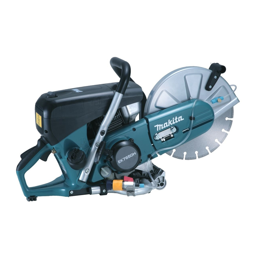
Models EK7650H and EK7651H are the world's first 4-stroke power cutters.
Their main features are:
• Low fuel consumption, low noise and clean exhaust emission achieved
by 4-stroke engine
• Easy start-up with Automatic decompression, Primer pump and
On/off choke combination switch with automatic half-throttle lock
• Low-vibration system with damper springs to absorb vibration from
engine to integrated front and rear handles.
Each wheel diameter is:
305mm (12") for model EK7650H
355mm (14") for model EK7651H
S
pecification
Specifications
Type
Displacement: cm³ (cu.in)
Engine
Fuel
Max. output: kW
Max. torque: N.m
Engine oil
Fuel consumption: L/h (US oz/h)
Fuel tank capacity: L (US oz)
Rapid start
Starting
(Spring-assisted recoil starter)
system
Decompression valve
Wheel diameter:
mm (")
Max. cutting depth:
Dry weight*
: kg (lbs)
2
*1 Some countries: E10 or E25 gasoline
*2 without cutting wheel
S
tandard equipment
Tool kit (Socket wrench 13-16, Hexalobular wrench, Slotted screwdriver and Tool bag)
Oil bottle (containing 220ml engine oil)
Water supply kit
Adapter ring (for some countries only)
Note: The standard equipment for the tool shown above may vary by country.
O
ptional accessories
Filter set
Trolley kit
Oil bottle set (10 bottles of 220ml engine oil)
Diamond wheel
Abrasive cut-off wheel
EK7650H, EK7651H
Power Cutters 305mm (12"), 355mm (14")
Model
mm (")
Length (L)
Width (W)
Height (H)
EK7650H
4-stroke
75.6 (4.6)
Straight unleaded gasoline*
3.0 (at 7,500 min.
4.6 (at 5,500 min.
SAE10W-30 oil
in the class SF or higher of API Classification
1.7 (57.5)
1.1 (37.2)
No
Automatic (Mechanical)
305 (12)
97 (3-13/16)
12.7 (28.0)
PRODUCT
P 1/ 19
Dimensions: mm (")
EK7650H
EK7651H
761 (30)
780 (30-3/4)
310 (12-1/4)
435 (17-1/8) 455 (17-7/8)
EK7651H
1
¹)
ˉ
¹)
ˉ
355 (14)
122 (4-13/16)
12.9 (28.4)
Advertisement

Related Manuals for Makita EK7650H


Summary of Contents for Makita EK7650H
- Page 1 Description Power Cutters 305mm (12"), 355mm (14") ONCEPT AND MAIN APPLICATIONS Models EK7650H and EK7651H are the world’s first 4-stroke power cutters. Their main features are: • Low fuel consumption, low noise and clean exhaust emission achieved by 4-stroke engine •...
- Page 2 P 2/ 19 epair CAUTION: Repair the machine in accordance with “Instruction manual” or “Safety instructions”. Warning: Follow the instructions described below in advance before repairing: • Wear gloves. • Remove the cutting tool from the unit. • When the engine is hot from use, cool down the engine enough or you can get burned. •...
- Page 3 • Contact surface with Push rod Cam lifter R • Contact surface with Cam gear complete Oil seal 17 Inner periphery Makita grease N No. 2 a little • Steel balls in Ball bearings 6204LU and 6204 4-cycle Engine oil Crankshaft a little •...
- Page 4 P 4/ 19 epair [4] DISASSEMBLY/ASSEMBLY [4]-1. V-belt 5-800, Cutting device DISASSEMBLING (1) Loosen two M8 Hex nuts slightly with Wrench 13-16 of a standard accessory. (Fig. 2) (2) Release the tension on V-belt 5-800 by turning M6 Tensioning screw counterclockwise with Screwdriver. The position of M6 square nut shows the tension level;...
- Page 5 P 5/ 19 epair [4] DISASSEMBLY/ASSEMBLY [4]-1. V-belt 5-800, Cutting device (cont.) ASSEMBLING Assemble their parts by reversing the disassembly procedure. (1) Assemble one of Ball bearing 6203LLU to Cutting holder, then snap Retaining ring R-40 into the groove of Cutting device to secure the bearing.
- Page 6 Spiral spring in place in Reel first, then by winding Spiral spring here. Spiral spring counterclockwise towards the center of Reel. (Fig. 13) (2) Apply a little amount of Makita grease N No.2 to the whole surface of Spiral spring. (3) Put Starter rope through Starter case complete.
- Page 7 P 7/ 19 epair [4] DISASSEMBLY/ASSEMBLY [4]-3. Clutch, Ratchet DISASSEMBLING Fig. 16 (1) Remove Cutting device. Refer to the clause of [4]-1. (2) Loosen three M5x12 Hexalobular socket head bolts, then remove Clutch cover together with Starter assembly. (Fig. 16) (3) Loosen three M5x16 Hexalobular socket head bolts with 1R290 Clutch cover and Cordless impact driver, and remove Ratchet complete.
- Page 8 P 8/ 19 epair [4] DISASSEMBLY/ASSEMBLY [4]-4. Flywheel, Ignition coil Fig. 22 DISASSEMBLING FLYWHEEL COMPLETE (1) Loosen four M5x30 - Hexalobular socket head bolts, then remove Fan cover. (Fig. 22) (2) Remove M10 Flange nut from Crankshaft by turning counterclockwise by using Cordless impact driver with 14mm flats width Socket bit.
- Page 9 P 9/ 19 epair [4] DISASSEMBLY/ASSEMBLY [4]-4. Flywheel, Ignition coil (cont.) DISASSEMBLING IGNITION COIL (1) Loosen M6x15 Thumb screw, then remove Top cover. (Fig. 27) (2) Loosen four M5x40 Hexalobular socket head bolts, then remove Filter cover complete (Fig. 28) and Air filter.
- Page 10 P 10/ 19 epair [4] DISASSEMBLY/ASSEMBLY [4]-5. Carburetor Fig. 32 (1) After completion of the steps (1) and (2) on [4]-4, remove Grip cover by loosening 5.5x20 Hexalobular tapping screw. (Fig. 32) (2) Loosen two M5x45 Hexalobular socket head bolts, then remove Carburetor and Filter gasket from Carburetor mount.
- Page 11 P 11/ 19 epair [4] DISASSEMBLY/ASSEMBLY [4]-5. Carburetor (cont.) ADJUSTMENT OF CARBURETOR AFTER REPLACEMENT Pull throttle lever fully after a while engine running at idle position. When there is Fig. 38 a problem with the engine quick acceleration, adjust H needle (Fig. 38) as follows: (1) Warm up the engine by pulling the throttle lever fully for one minute.
- Page 12 P 12/ 19 epair [4] DISASSEMBLY/ASSEMBLY [4]-6. Throttle lever Fig. 42 DISASSEMBLING (1) Remove Pin 5 from the grooves on Tank complete by levering it up with a slotted screwdriver. (Fig. 42) (2) Expand the hinge portion for Throttle lever on Tank complete with 1R003. (Fig.
- Page 13 P 13/ 19 epair [4] DISASSEMBLY/ASSEMBLY [4]-7. Engine block (cont.) DISASSEMBLING (6) Remove four M6x30 Hexalobular socket head bolts that fasten Front handle, Tank complete and Engine. (Fig. 46) Engine block can be removed. (Fig. 47) Fig. 46 [Viewed from Blade installation side] [Viewed from Starter assembly installation side] M6x30 Hexalobular socket M6x30 Hexalobular socket...
- Page 14 P 14/ 19 epair [4] DISASSEMBLY/ASSEMBLY [4]-8. Engine DISASSEMBLING (1) Remove Clutch complete and Clutch drum. Refer to [4]-3. (2) Remove Flywheel. Refer to [4]-4. If necessary, remove Ignition coil. (3) Loosen five M6x25 Hexalobular socket head bolts, then remove Cutting arm from Cylinder block complete. (Fig. 48) (4) Remove Exhaust muffler from Cylinder block complete.
- Page 15 P 15/ 19 epair [4] DISASSEMBLY/ASSEMBLY [4]-8. Engine (cont.) DISASSEMBLING Note: Cam gear assembly functions as automatic decompression valve system. Valve is slightly open to release the compressed air in Engine at the starting time, before moving fly weight by centrifugal effects. It means the insufficient setting of Cam gear assembly will cause engine stall/ extreme reaction force at engine running due to too much load by the compressed air.
- Page 16 P 16/ 19 epair [4] DISASSEMBLY/ASSEMBLY [4]-8. Engine (cont.) DISASSEMBLING Important: When Intake/ Exhaust valves have to be replaced, remove Cylinder head complete. (Refer to previous page.) (5) Loosen eleven Hexalobular socket head bolts on the bottom of Crank case (Fig. 58), then remove Crank case from Cylinder block.
- Page 17 [4]-8. Engine (cont.) ASSEMBLING ENGINE BLOCK Note: Be sure to apply Makita grease N No.2/ 4-cycle engine oil in accordance with [3] LUBRICANT APPLICATION. (1) Connect Piston with Crankshaft complete by inserting Piston pin into place; there is no front/back to Piston.
- Page 18 P 18/ 19 epair [4] DISASSEMBLY/ASSEMBLY [4]-8. Engine (cont.) DISASSEMBLING (8) Assemble Cam gear section by reversing the disassembly procedure. (Refer to Fig. 53 and 52.) (9) Move Piston to the upper dead point in Cylinder block by turning Crankshaft slowly and carefully by hand. (10) Adjust the gap between Rocker arms and Exhaust valve section/ Intake valve section as follows: A.
- Page 19 P 19/ 19 epair [4] DISASSEMBLY/ASSEMBLY [4]-9. Ignition system (cont.) CHECKING SPARK PLUG WARNING !! • When a spark is produced, high-voltage current is delivered from Ignition coil to Spark plug. It is, therefore, very dangerous to pull Recoil starter knob with your hand on Ignition cable. Be sure to keep your hands off from Ignition cable when checking for spark.