
Related Manuals for GE ABB ReliaGear SB


Summary of Contents for GE ABB ReliaGear SB
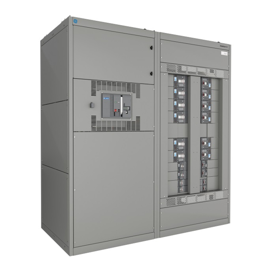
- Page 1 I N S TA L L AT I O N , O P E R AT I O N S A N D M A I N T E N A N C E M A N UA L ReliaGear® SB Switchboards...
- Page 3 TA B L E O F C O N T E N T S Table of contents Safety measures and classifications 05 – 07 Pre-installation 08 – 11 Installation: Switchboard location and requirements 12 – 21 Installation: Multiple switchboard 22 – 25 Installation: Accessories and devices 26 –...
- Page 4 R E L I A G E A R ® S B S W I TC H B O A R D S Safety measures and classifications Read the following hazard classifications carefully, This document is based on information available and fully inspect the equipment for any identifiable at the time of its publication.
- Page 5 I N S TA L L AT I O N , O P E R AT I O N S A N D M A I N T E N A N C E M A N U A L Pre-installation —...
- Page 6 R E L I A G E A R ® S B S W I TC H B O A R D S — Crane / Hoist Lifting slings, spreaders, blocking, and other lifting equipment is not included with the switchboard. Lifting hooks as installed —...
- Page 7 I N S TA L L AT I O N , O P E R AT I O N S A N D M A I N T E N A N C E M A N U A L —...
- Page 8 R E L I A G E A R ® S B S W I TC H B O A R D S Installation: Switchboard location and requirements Before installation Front access Before any installation work is performed, study all The space in front of the switchboard must drawings furnished by the supplier.
- Page 9 I N S TA L L AT I O N , O P E R AT I O N S A N D M A I N T E N A N C E M A N U A L —...
- Page 10 R E L I A G E A R ® S B S W I TC H B O A R D S — Seismically certified equipment ½-13 Bolt; min. legth 1.50inch For seismically certified switchboards of IBC-2018 Installation of seismically ½...
- Page 11 I N S TA L L AT I O N , O P E R AT I O N S A N D M A I N T E N A N C E M A N U A L Torque specifications Neutral-to-ground spacing should be based on the Switchboards are furnished with medium carbon...
- Page 12 R E L I A G E A R ® S B S W I TC H B O A R D S Installation: Multiple switchboard sections — Joining section frames The joining of the sections involves two bolted Top and bottom bolted Section 1 connection, two connections each on the top and bottom depth...
- Page 13 I N S TA L L AT I O N , O P E R AT I O N S A N D M A I N T E N A N C E M A N U A L —...
- Page 14 R E L I A G E A R ® S B S W I TC H B O A R D S — Main bus Main bus splice splice Main bus splice – Front and Top Views for two Main bus Main bus individually mounted...
- Page 15 I N S TA L L AT I O N , O P E R AT I O N S A N D M A I N T E N A N C E M A N U A L —...
- Page 16 R E L I A G E A R ® S B S W I TC H B O A R D S — The offset splice assembly consists of two bus bar sets, already installed from the factory. One of the Offset Main Bus Splice - Alignment of two sets is installed on the left section and the...
- Page 17 I N S TA L L AT I O N , O P E R AT I O N S A N D M A I N T E N A N C E M A N U A L —...
- Page 18 R E L I A G E A R ® S B S W I TC H B O A R D S — The offset neutral bus splice assembly consists of a ‘Z’ shaped bus bar that connects two neutral buses. Neutral Offset Bus Splice –...
- Page 19 I N S TA L L AT I O N , O P E R AT I O N S A N D M A I N T E N A N C E M A N U A L —...
- Page 20 R E L I A G E A R ® S B S W I TC H B O A R D S — Splicing ReliaGear/ Evolution and Spectra bus – Top and Front Detail A Views of 3000A bus configuration (shown for reference).
- Page 21 I N S TA L L AT I O N , O P E R AT I O N S A N D M A I N T E N A N C E M A N U A L —...
- Page 22 R E L I A G E A R ® S B S W I TC H B O A R D S Installation: Accessories and devices DANGER — For circuit breakers and accessories, refer to WARNING the individual instruction manuals provided Cable Brace –...
- Page 23 I N S TA L L AT I O N , O P E R AT I O N S A N D M A I N T E N A N C E M A N U A L Ground •...
- Page 24 R E L I A G E A R ® S B S W I TC H B O A R D S DANGER — Testing and inspection Typical single-source WARNING ground-fault protection using ground-fault relays Warning: Keep equipment de-energized during —...
- Page 25 I N S TA L L AT I O N , O P E R AT I O N S A N D M A I N T E N A N C E M A N U A L After thorough cleaning and inspection, if the For field commissioning of the Reduced Energy megohm reading is still low, it may still be safe to...
- Page 26 R E L I A G E A R ® S B S W I TC H B O A R D S Switchboard maintenance General maintenance procedures • Retorque terminal connections and hardware To obtain the best service from the switchboard, to the values specified in Table 1 to eliminate establish a periodic maintenance schedule.
- Page 27 I N S TA L L AT I O N , O P E R AT I O N S A N D M A I N T E N A N C E M A N U A L Arcing damage to insulation When equipment has become exposed to non- Some organic insulating materials carbonize when...
- Page 28 R E L I A G E A R ® S B S W I TC H B O A R D S Reference document numbers Installation manuals Additional technical information, instructions and installation manuals can be found in the following documents: •...
- Page 29 I N S TA L L AT I O N , O P E R AT I O N S A N D M A I N T E N A N C E M A N U A L Reference standards All ABB switchboards meet the following standards: •...
- Page 30 R E L I A G E A R ® S B S W I TC H B O A R D S...
- Page 32 305 Gregson Drive Cary, NC 27511 USA abb.com/contacts abb.com/lowvoltage GE is a trademark of GE. Manufactured by ABB Ltd under license from General Electric Company. The information contained in this document is for general information purposes only. While ABB strives to keep...