Table of Contents
Advertisement
Quick Links
Advertisement
Table of Contents

Related Manuals for GE Entellisys


Summary of Contents for GE Entellisys
- Page 1 DEH-237 BCS Switchgear Inc. Switchgear | Circuit Breakers | Parts | Tech Support GE Entellisys™ Low Voltage Switchgear ________________________________________________ Installation and Maintenance Instructions bcsswitchgear.com | 888.599.0486 Need Help? 888.599.0486...
- Page 2 BCS Switchgear Inc. Switchgear | Circuit Breakers | Parts | Tech Support bcsswitchgear.com | 888.599.0486 Need Help? 888.599.0486...
- Page 3 Features may be described herein that are not present in all hardware and software systems. GE Consumer & Industrial assumes no obligation of notice to holders of this document with respect to changes subsequently made.
-
Page 4: Table Of Contents
Key Interlocks........51 EGF-50 Rollout Carriage ....17 Breaker Operation Test ..... 51 Compartments for Future Breakers .. 18 Entellisys System Test Kit ....51 Auxiliary/Transition Sections .... 18 Final Steps to Be Taken Before 3-10 Bus Area..........19 Energizing Equipment ....... 52 Busing System ........ - Page 5 Removal and Installation.... 54 Paint Refinishing ....... 63 Door Removal ......54 Circuit Breaker Lifting Mechanism .. 63 Door Installation...... 54 Entellisys Switchgear Accessories ..55 Appendices Future Circuit Breaker Torque Values........65 Compartments ......55 Circuit Breaker Rejection Features... 66 Circuit Breaker Key Interlock ..
-
Page 7: Chapter 1. Introduction
Entellisys Low Voltage Switchgear Chapter 1. Introduction 1-1 General Information • Chapter 3, Description, describes the Entellisys Low This manual contains procedures for receiving, handling, storage, equipment installation, operation, maintenance, and Voltage Switchgear various components. service of Entellisys Low Voltage Switchgear. -
Page 8: Related Publications
3. Summary of all the components furnished with the In addition to instruction books, the following drawings will switchgear, including the breakers, identified by catalog be supplied as required for each order of Entellisys number. switchgear equipment: These are all documents necessary to install, operate, and 1. -
Page 9: Chapter 2. Receiving, Handling, And Storage
Entellisys Low Voltage Switchgear Chapter 2. Receiving, Handling, and Storage 2-1 Receiving Equipment Packages Every package leaving the factory is plainly marked with the shop order number, requisition number, and customer's order number. If the equipment has been split for shipment, the section numbers of the equipment enclosed in each shipping package are identified. -
Page 10: Handling
HEAD SPACE IS moins de 45 degrés. INSUFFICIENT, USE A Si l’espace de dégagement SPREADER BAR. est insuffisant utiliser une barre d’écartement. THIS LABEL IS LOCATED ON EACH CORNER BY THE LIFTING HOLE Fig. 2-3. Recommended method of lifting Entellisys enclosure... -
Page 11: Rollers
Une détérioration ou un désenlignement des composantes internes sont possibles si le dispositif de Fig. 2-4. Placing forklift tines under Entellisys commutation est manipulé grossièrement ou soumis à des equipment shipping skid vibrations. -
Page 12: Jacks
Entellisys Low Voltage Switchgear Chapter 2. Receiving, Handling, and Storage Fig. 2-6. Method of rolling equipment into place ATTENTION: Il ne faut pas placer de vérins en aucun 7. While carefully pushing the switchgear to its final site endroit autre que les coins avants et arrières du dispositif position, the rollers that are freed from the rear of the de commutation. -
Page 13: Storage
Entellisys Low Voltage Switchgear Chapter 2. Receiving, Handling, and Storage 2-3 Storage required. Incandescent lamps may be used for this purpose. These lamps should be located in the bottom Switchgear breaker compartment of each section and supported so the bulbs will not touch adjacent materials. -
Page 14: Chapter 3. Description
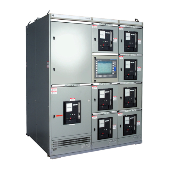
Chapter 3. Description 3-1 General 3-2 Summary Description This section contains a description of the General Electric General Electric Entellisys Low Voltage Switchgear is a Entellisys Low Voltage Switchgear. It also describes the freestanding assembly of metal-enclosed sections containing functions of the electrical and mechanical systems. - Page 15 EntelliGuard Messengers. The unit substation illustrating the nomenclature used for all breakers are provided with self-aligning primary and equipment. secondary disconnect contacts and a breaker mechanism Fig. 3-2. Outline of a typical Entellisys Load Center Unit Substation...
-
Page 16: Compartment Area
Two CPUs (Central Processing Units) provide EntelliGuard low voltage power circuit breakers or Entellisys the processing capability to support all switchgear functions. At least one HMI (Human-Machine Interface) provides user instrumentation. access to the Entellisys system. Network switches provide... -
Page 17: Breaker Compartment
Closed-door drawout circuit breaker compartments, Fig. interruption. 4, are standard construction with all Entellisys switchgear equipment. The circuit breaker compartment doors remain closed and latched while the breaker is racked out Additionally, the breaker compartment, Fig. - Page 18 Entellisys Low Voltage Switchgear Chapter 3. Description Side barrier Primary disconnects -- load Bottom barrier Drawout rails Rear base/barrier Racking anchor pins Primary disconnects – line Secondary Disconnect Current Transformers Fig. 3-5 Circuit breaker compartment (22-inch)
- Page 19 Entellisys Low Voltage Switchgear Chapter 3. Description Fuses for the charge, close, and trip circuits of electrically operated breakers are mounted in the upper left corner of the NOTE: If a fuse rollout (FRE) carriage is used with an breaker compartment behind the door. Fuses for the set and...
- Page 20 (5) behind the shutter assembly. Stationary barrier Shutters (not visible in retracted position) Operating lever Operating lever springs Primary disconnect stabs Fig. 3-7. Entellisys primary disconnect shutter assembly (30-inch wide compartment). Shutters manually retracted...
- Page 21 EntelliGuard breakers do not contain current transformers. Instead, current transformers are mounted over the primary 1. CONNECTED POSITION-The breaker is in operating disconnect stabs of all Entellisys breaker compartments. position, both primary and secondary contacts made, Primary disconnects are equipped with short-circuit braces and the door closed.
-
Page 22: Circuit Breakers
Fig. 3-10. EGX-08 circuit breaker (electrically operated) Six General Electric EntelliGuard™ Circuit Breakers form EGF-16 Fused Circuit Breaker the complete family of breakers used in the Entellisys • 1600-ampere frame size switchgear. These circuit breakers range from 800 to 5000 •... -
Page 23: Circuit Breaker
Entellisys Low Voltage Switchgear Chapter 3. Description EGS/EGH/EGX/EGF -32 Circuit Breaker EGF-32 Rollout Carriage • 3200-ampere frame size • 3200-ampere rating • Standard 65,000-ampere interrupting and short-time • 200,000-ampere interrupting rating capability at 480 volts • Accepts 2000- through 4000-ampere fusing •... -
Page 24: Compartments For Future Breakers
Entellisys Low Voltage Switchgear Chapter 3. Description Quarter-turn latch Compartment door Steel plate (future breaker cubicle) Fig. 3-13. Future breaker compartment 3-8 Compartments for Future 3-9 Auxiliary/Transition Sections Breakers Sections may be provided for any one or more of several... -
Page 25: Bus Area
Entellisys Low Voltage Switchgear Chapter 3. Description 3-10 Bus Area Busing System Bus bars are fully tin-plated copper with bolted joints. The The bus area, 3-14, contains the main horizontal bus and Fig. standard construction is open bus. A barrier system (Bus vertical riser bus bars (1) for the particular section. -
Page 26: Insulated/Isolated Bus System
Chapter 3. Description Insulated/Isolated Bus System A bus insulation system, 3-16, that fully insulates each Fig. phase of the horizontal main bus and isolates each phase of the vertical bus, is optionally available for Entellisys switchgear when specified. With INSULATED/- ISOLATED BUS system, there are no live connections accessible in the rear of each section except the cable lugs. - Page 27 Entellisys Low Voltage Switchgear Chapter 3. Description the bus bars. (The top portion of the vertical bus is shown A vertical barrier (2), 3-17, between the transition Fig. with the cover removed.) section (1) and the first breaker section is always furnished.
-
Page 28: Feeder Cable And Busway Compartment
Entellisys Low Voltage Switchgear Chapter 3. Description Fig. 3-19 illustrates the various components comprising the 3-11 Feeder Cable and Busway insulation/isolation system for the horizontal main bus bars. Compartment The horizontal bus bars (2) are insulated with an epoxy coating applied by a fluidized bed process. -
Page 29: Ground Bus
Entellisys Low Voltage Switchgear Chapter 3. Description 3-12 Ground Bus All General Electric Entellisys switchgear sections are grounded to the internal equipment ground bus (4), Fig. 3-21, located at the bottom of the cable compartment. Feeder runbacks Vertical riser bus covers... -
Page 30: Chapter 4. Equipment Installation
Anchor bolts and In locating the Entellisys Switchgear, adequate aisle space channels are to be provided by the purchaser. must be provided at the front and rear of the equipment to ensure proper ventilation of the equipment and to allow service and maintenance of the equipment with the front and rear doors open. - Page 31 à des charges d’impact (choc) causées par les conditions d’opération ou des séismes environnementaux Entellisys Switchgear and Load Center Substations are (tremblements de terre), les boulons d’ancrage devraient frequently mounted on steel floors and/or structural steel in être fabriqués d’acier à moyenne teneur en carbone industrial installations (such as a mezzanine) to minimize (spécification de charge classe 5).
- Page 32 Entellisys Low Voltage Switchgear Chapter 4. Equipment Installation If studs or anchor bolts are to be used, they should be cover all of the standard enclosures available for installed in the foundation as it is poured. It is important Entellisys Switchgear.
-
Page 33: Assembly And Installation Of Switchgear Equipment
Entellisys Low Voltage Switchgear Chapter 4. Equipment Installation 4-2 Assembly and Installation of Switchgear Equipment General Requirements Before assembling or installing the switchgear equipment, all components should be available at the site location. This will facilitate switchgear component identification as well as installation. - Page 34 Entellisys Low Voltage Switchgear Chapter 4. Equipment Installation Fig. 4-5. View showing method of attaching equipment to shipping skids NOTE: All mating sections of the equipment line-up (including transformer, if applicable) must be securely fastened together prior to tightening anchor bolts fastening the equipment to the mounting surface.
- Page 35 This includes the installation of splice Fig. 4-8. Typical location of buses at shipping split plates for the main bus bars, the neutral bus, and the ground bus in addition to the Entellisys control and communication circuitry. WARNING: switchgear...
- Page 36 Entellisys Low Voltage Switchgear Chapter 4. Equipment Installation The ground bus is mounted directly on the rear upright If a GE transformer (rated above 750 kVA) is present in the channels. line-up, a ground bar located in the transition compartment, Fig.
- Page 37 Entellisys Low Voltage Switchgear Chapter 4. Equipment Installation All bolted bus joints should be made using the proper torque as shown in Table A-1 in Appendix A of this manual. Transformers not manufactured by General Electric may require special mounting and bus connection hardware.
- Page 38 Entellisys Low Voltage Switchgear Chapter 4. Equipment Installation After completing the installation of the main bus splice bars, the joint covers may be mounted and secured by a 3/8-16 6. INTERCONNECT ENTELLISYS CONTROL nylon bolt and polyester flat washer if the bus insulation COMMUNICATION WIRING - Interconnection of option has been supplied with the equipment.
-
Page 39: Anchoring Switchgear Equipment
Entellisys Low Voltage Switchgear Chapter 4. Equipment Installation Anchoring Switchgear Equipment b. The rear of the equipment may be anchored by one of three procedures: Correct anchoring of the switchgear equipment to the foundation is very important. After completion of re- •... - Page 40 Entellisys Low Voltage Switchgear Chapter 4. Equipment Installation Channel sill 3/16-inch fillet weld Front width post Plug weld in anchor bolt hole Rear sill angle Rear width post Fig. 4-15. Equipment weld anchoring...
-
Page 41: Busway Connections
Connect the cables to the terminal blocks in accordance contact surfaces be coated with a film of GE lubricating with the connection diagrams for the equipment. Refer grease D6A15A2. A can of this grease is supplied with the to the equipment frontview / floorplan drawings for equipment. -
Page 42: Power Cable Connections
Bolt the cable terminal connectors to the ends of the bars For copper cables, coat the wires with GE lubricating in the cable compartment. Non-oxidizing grease, such as grease D6A15A2, insert the cables into the terminals, and... -
Page 43: Breaker Hoist
Entellisys Low Voltage Switchgear Chapter 4. Equipment Installation Breaker Hoist dispose of this guide since it must be reinstalled after mounting the hoist on the equipment. Fig. 4-18 shows the breaker hoist assembled on a switchgear lineup. The hoist is shipped in a separate carton completely... -
Page 44: Final Inspection
Entellisys Low Voltage Switchgear Chapter 4. Equipment Installation The hoist should be lifted into position on top of the switchgear so that the end with two rollers is toward the rear of the equipment, Fig. 4-21. Fig. 4-23. Replacing the runner guide after completion of hoist installation Fig. -
Page 45: Installation Of Wall-Mount Hmi
Entellisys Low Voltage Switchgear Chapter 4. Equipment Installation 4-3 Installation of Wall-Mount HMI proper sealing and enclosure protection rating, use the provided sealing washers. Install the sealing washers inside the enclosure with the tapered cone against the enclosure and then add the flat washers General Requirements as shown in Figs. - Page 46 Entellisys Low Voltage Switchgear Chapter 4. Equipment Installation Ethernet port Areas suitable for conduit hole Power Supply Terminal Block RS232/RS485 Converter Fig. 4-28. HMI enclosure and devices...
-
Page 47: Chapter 5. Installing And Removing Circuit Breakers
Be sure that a thin film of GE lubricating grease being racked onto the primary stabs. D6A15A2 is present on primary disconnects of the switchgear before installing the breaker. -
Page 48: Installing Eg-08/16/20 Circuit Breakers
2. Verify that the breaker is the correct type for that compartment. 3. Ensure that the breaker is OPEN. 4. Apply a thin fresh coat of GE lubricating grease D6A15A2 to the breakers primary disconnects. 5. Ensure that the racking forks on the breaker are correctly positioned for initial engagement with the pins in the compartment. - Page 49 Entellisys Low Voltage Switchgear Chapter 5. Installing and Removing Circuit Breakers Fig. 5-4. Reel out hoist cable. Attach spreader bar assembly Fig. 5-5. Hoist breaker above rails to circuit breaker Fig. 5-7. Lower the breaker onto the rails of the cell.
- Page 50 Entellisys Low Voltage Switchgear Chapter 5. Installing and Removing Circuit Breakers CAUTION: When using the switchgear hoist, do not un- wind the cable completely from the drum. To lift the breaker, turn the hoist operating crank clockwise. lower the breaker, turn the hoist operating crank counter- clockwise.
-
Page 51: Installing Eg-32/40/50 Circuit Breakers
Entellisys Low Voltage Switchgear Chapter 5. Installing and Removing Circuit Breakers 5-3 Installing EG-32/40/50 Circuit Breakers 7. Slide rails back into compartment. Close compartment door and rotate latch ¼ turn counter- clockwise. WARNING: Do not stand under the circuit breaker during the hoisting operation. -
Page 52: Removing The Egs-08/16/20 Circuit Breakers
Entellisys Low Voltage Switchgear Chapter 5. Installing and Removing Circuit Breakers 5-4 Removing the EG-08/16/20 Circuit 5-5 Removing the EGS-32/40/50 Breakers Circuit Breakers WARNING: Do not stand under the circuit breaker WARNING: Do not stand under the circuit breaker during the lowering operation. -
Page 53: Installing Fuses In Egf-08/16 Circuit
Entellisys Low Voltage Switchgear Chapter 5. Installing and Removing Circuit Breakers 5-6 Installing and Removing EGF- 08/16 Fused Circuit Breakers Except for the open fuse lockout device and the integrally mounted fuses on the upper studs, the EGF-08 and -16 breakers are identical to the non-fused EGS-08 and -16 models. - Page 54 Entellisys Low-voltage Switchgear Chapter 5. Installing and Removing Circuit Breakers 1. Remove the primary disconnect assembly from the fuse CAUTION: When replacing the fuse in the right pole tang. This is accomplished by first loosening the two (plan view) of the breaker, note particularly that this fuse keys (2), Fig.
-
Page 55: Installing And Removing Fuse Rollout Elements (Fre) 30 And 38-Inch Wide Compartments
Entellisys Low-voltage Switchgear Chapter 5. Installing and Removing Circuit Breakers Fig. 5-16. Mounting for special 2500-ampere fuse on EGF-16 breaker Fig. 5-17. Fuse rollout carriage (FRE) showing hinged, perforated steel screen panel 5-8 Installing and Removing Fuse Rollout Elements (FRE)-30-38-inch... - Page 56 Entellisys Low-voltage Switchgear Chapter 5. Installing and Removing Circuit Breakers The breaker is prevented from being closed until the key is reinserted and captured in the breaker compartment key interlock mechanism. Secondary disconnects on the FRE provide the voltage signals across each fuse to the OPEN FUSE LOCKOUT DEVICE on the associated circuit breaker, Fig.
-
Page 57: Chapter 6. Testing And Inspection
6-4 Entellisys System Test Kit exceed 75 percent of the IEEE factory test voltage. For the power circuit, the IEEE factory test voltage is two An Entellisys System Test Kit is required for testing times switchgear rating plus 1,000 volts. See Table 6-1. -
Page 58: Final Steps To Be Taken Before Energizing Equipment
Using the Entellisys HMI, exercise all EntelliGuard breakers to determine all devices work correctly. See Energizing Equipment DEH-231 for instructions on using the Entellisys HMI. The following steps should be taken before energizing the Test all protection functions using the Entellisys equipment: System Test Kit. -
Page 59: Chapter 7. Operating The Switchgear
Electrically Operated Breakers The breakers may be closed by a mechanically operated, double insulated push-button switch on the breaker escutcheon or by the Entellisys HMI. Fuses are located in the breaker compartment, just behind the door. Electrically Opening EntelliGuard Breakers Fig. -
Page 60: Drawout Operation
7-3 Front Doors Operation The front access doors on all standard Entellisys Switchgear Fig. 7-2. Entellisys switchgear front access doors are hinged with a are hinged and equipped with a ¼-turn latch, Fig. 7-3. To rotary-type latch open the door, rotate the knob clockwise ¼ turn. -
Page 61: Entellisys Switchgear Accessories
Entellisys Low Voltage Switchgear Chapter 7. Operating the Switchgear 7-4 Entellisys Switchgear bolt may be extended and the key removed. breaker will remain trip free in the CONNECT position Accessories until the key is returned and the lock bolt is retracted. -
Page 62: Padlocking The Eg-08/16/20 Breakers
Assurez-vous de court-circuiter les secondaires avant de bouger un transformateur de courant. Padlocking the EG-32/40/50 Breakers & EG-32/40/50 FRE Fuse Rollout Element (See Fig. 7-7.) Phase current transformers (CT's) in Entellisys Low Voltage Switchgear mounted stationary primary 1. The circuit breaker compartment door must be opened disconnect studs in the breaker compartment and are readily to put the padlock on;... -
Page 63: Removing Shutter Units
Spring Frame assembly 8. Support block Complete upper shield Shutter Actuator 9. Bottom shield assembly Bottom shutter 10. Connector link Shield cover Support Block 11. Spring Label Center shield 12. Spring Fig. 7-9. Entellisys circuit breaker shutter unit (EGS-08/16 breakers) -
Page 64: Removing A
5. Shutters 3. Movable shield assembly 6. Shutter actuator Fig. 7-10. Entellisys circuit breaker shutter unit (EG-32/40/50 breakers) Removing an EG-08/16/20-Shutter Unit The frame is then maneuvered forward past the cam plates on each side, then upward and forward over the To remove these shutter units, proceed as follows: cam pins. -
Page 65: Installing A Shutter Unit
Entellisys Low Voltage Switchgear Chapter 7. Operating the Switchgear Installing a Shutter Unit If it was present, reinstall the Clamp Circuit. Reconnect the 12 wires in the same positions as they were before. Reattach the enclosure to the side WARNING: Unless the proper precautions are taken, sheet using ¼”-inch hex head screws... -
Page 66: Chapter 8. Energizing The Switchgear
The equipment should be energized in sequence by starting at the source end of the system and working toward the load end. In other words, energize the main devices, then the feeder devices, and then the branch- circuit devices. Turn the devices on using the Entellisys HMI. -
Page 67: Chapter 9. Maintaining The Switchgear
For specific information regarding the maintenance of circuit a. For the EG-32/40/50 frame breakers, raise the breakers and Entellisys instrumentation, refer to the breaker frame off the work surface to ensure the instruction book furnished with each device. -
Page 68: Lubrication
In general, the circuit breaker requires moderate lubrication. Bearing points and sliding surfaces should be lubricated at WARNING: De-energize equipment completely before the regular inspection periods with a thin film of GE doing maintenance work on any devices, connections, bus lubricant D6A15A2. Before lubricating, remove any work, breaker or feeder cable compartments. -
Page 69: Overall Switchgear
Entellisys Low Voltage Switchgear Chapter 9. Maintaining the Switchgear ATTENTION: Assurez-vous que la condition ayant causé le surchauffement a été corrigée avant de mettre sous 9-6 Paint Refinishing tension. Indoor switchgear is finished with ANSI-61 gray acrylic Check all bolts that hold cable terminals to the enamel paint. -
Page 70: Torque Values
Entellisys Low Voltage Switchgear Appendix A. Torque Values Table A-1—Torque Values for Low- voltage Equipment Table A-2—Torque Values for Self-threading Screws in Electrical Joint Hardware other than Cable Terminals Plastic (Copper, Tin or Silver Plated) Wire Torque* Size (in/lbs) Torque*... - Page 71 Entellisys Low Voltage Switchgear Appendix B. Circuit Breaker Rejection Features General 22-inch Wide Compartment In general, EntelliGuard breakers of the same type and Figure B-1 (EG-08/16/20 breaker family) shows the breaker- rating are interchangeable in their equipment compartments. mounted rejection tabs located on the bottom left side of the Similarly, breakers may be installed into equipment backframe.
-
Page 72: Circuit Breaker Rejection Features
Entellisys Low Voltage Switchgear Appendix B. Circuit Breaker Rejection Features EGX-08 shown Circuit Breaker Rejection Pin Position Type EGS-08 ¡ ¡ ¡ ¡ ¡ ¡ ¡ EGH-08 ¡ ¡ ¡ ¡ ¡ ¡ EGX-08 ¡ ¡ ¡ ¡ ¡ EGF-08 ¡... - Page 73 30 & 38-inch Wide Compartment An EGX-32 or EGX-40 can be inserted into an EGH- 32 compartment. EG-32/40/50 breakers and fuse rollouts for Entellisys switchgear include means to prevent improper interchange of An EGX-40 can be inserted into an EGX-32 these 3200-, 4000-, and 5000-ampere sizes.
- Page 74 Entellisys Low Voltage Switchgear Appendix B. Circuit Breaker Rejection Features The rejection tab logic shown in Fig. B-3 is for EntelliGuard breakers only. Rejection pin patterns on the breakers prevent their installation into AKD-10™ equipment compartments. Likewise, rejection pins Entellisys equipment compartments prevent installation of WavePro™...
- Page 75 Entellisys Low Voltage Switchgear Appendix C. Circuit Breaker Ratings System Three-phase Short Circuit Rating RMS Symmetrical kA Frame Nominal Short With Without Size Breaker Voltage Time Instantaneous Instantaneous (Amperes) Type (60 HZ AC) Withstand Trip Trip EGS-08 EGH-08 EGX-08 1600...
-
Page 76: Circuit Breaker Ratings
Entellisys Low Voltage Switchgear Appendix D. Circuit Breaker Accessory Devices Shunt Trip Remote Close The Shunt Trip allows the breaker to be opened remotely by The Remote Close accessory provides a means of remotely the EntelliGuard Messenger™. It is always provided on closing the circuit breaker after the closing springs have electrically operated breakers. -
Page 77: Circuit Breaker Accessory Devices
Entellisys Low Voltage Switchgear Appendix D. Circuit Breaker Accessory Devices OFLO OFLO OFLO Lockout Status Phase A Phase B Phase C Trip Coil Contact Figure D-3. Open-Fuse Lockout (OFLO) connections to the Secondary Disconnect Figure D-4. Bell Alarm with Lockout connections to the Secondary Disconnect. - Page 78 Circuit breakers are designed primarily to perform the the minimum performance that is indicated in Table F-1. function of circuit interruption under short-circuit conditions. With adequate maintenance, GE breakers can be expected to Nevertheless modern circuit breaker mechanisms are capable exceed the standards.
-
Page 79: Circuit Breaker Weights
Entellisys Low Voltage Switchgear Appendix F. Circuit Breaker Repetitive Duty Data This standard applies to all parts of a circuit breaker that perform at least one opening operation at rated short- function during normal operation. It does not apply to other circuit current. - Page 80 GE Consumer & Industrial General Electric Company 510 Agency Road, West Burlington, IA 52655 DEH237 R01 1205 © 2005 General Electric Company...