Table of Contents
Advertisement
Quick Links
Advertisement
Table of Contents
Troubleshooting

Related Manuals for GE PhastSystem


Summary of Contents for GE PhastSystem
- Page 1 user manual automated electrophoresis Phast System 80-1320-15 Edition AI...
-
Page 3: Table Of Contents
1. Contents Contents Introduction ..............5 Important safety information ......... 9 Connection to the mains supply ....... 9 Safety arrangements ..........9 Safety precautions ..........10 Description of the system ..........11 The separation and control unit ......11 The development unit ........... 15 PhastGel media and chemicals ....... - Page 4 GE Healthcare Bio-Sciences AB. GE Healthcare Bio-Sciences AB shall in no event be liable for incidental or consequential damages, including without limitation, lost profits, loss of income, loss of...
-
Page 5: Introduction
These components work together to form a system for fast, high-resolution, and reproducible electrophoresis. With PhastSystem, isoelectric focusing is as easy to perform as gel electrophoresis; Coomassie staining is as easy as silver staining. The schematic diagram below illustrates the steps involved in producing a finished electrophoresis gel using PhastSystem with PhastGel separation media. - Page 6 You will also find a list of the most common spare parts required for maintenance of PhastSystem. A list of the technical data on PhastSystem instruments and PhastGel media and accessories is also included. Chapter 9: Separation technique files;...
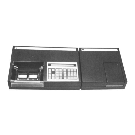
- Page 7 1. Introduction Phastsystem Fig.1. PhastSystem consists of a separation and control unit, a development unit, PhastGel separation media, accessories and a technical support package.
-
Page 9: Important Safety Information
2. Important safety information 2. Important safety information 2.1 Connection to Voltage selector setting the mains supply The instruments are available in two versions: one for 220-230/240 V AC, referred to here as the 220 V model, and one for 100/120 V AC, referred to here as the 120 V model. -
Page 10: Safety Precautions
2. Important safety information The voltage supplied by PhastSystem is capable of delivering a lethal 2.3 Safety electric shock. The numerous safety devices and circuits built into the precautions instrument prevent this. The “pause” and “start/stop” keys can also be pressed to halt the supply of power at any stage of the experiment or operation of PhastSystem. -
Page 11: Description Of The System
3. Description of the system 3. Description of the system The aim of this chapter is to introduce you to PhastSystem. Each component of PhastSystem is described in turn; the separation and control unit, the development unit, and PhastGel media and chemicals. - Page 12 3. Description of the system The Peltier element automatically cools and heats the separation bed to the programmed temperature. The programmable temperature range extends from 0°C to 70°C (see cooling capacity, page 14). The heat generated during electrophoresis is transferred to a large air cooled heat sink.
- Page 13 3. Description of thae system electrode assembly may take up two horizontal positions, depending on the setting of the two eccentric levers. The lower position is used for PhastGel IEF media, where the inner electrodes (the anode nearest the cathode and the cathode) rest directly on the gel. The higher posi- tion is used for PhastGel electrophoresis media, where the outer elec- trodes rest on PhastGel buffer strips which are held in place on the gel...
- Page 14 3. Description of the system For maximum reproducibility, the duration of each method step and the time for sample application is measured in volthours. Volthours indicate the extent of protein migration in the gel since electrophoretic mobility is proportional to the applied voltage and the time that this voltage is applied.
-
Page 15: The Development Unit
3. Description of the system Fig. 5 below shows the lowest separation bed temperature maintained (within ±l°C) for separations run at 4 and 7 watts with different ambient temperatures. Lower temperatures can be achieved but temperature drifts exceeding ±l°C might occur. Depending on the magnitude of the temperature drift, results may or may not be affected. - Page 16 3. Description of the system through a hole in the bottom of the chamber. Similarly, by creating excess pressure in the chamber, liquid is pushed out through the same hole in the bottom. Development methods Nine development methods are available for programming. For each method, you can program up to 20 steps.
- Page 17 3. Description of the system Fig. 7. 10-port valve. Chemical resistance The parts that come into contact with development solutions in the development unit are resistant to chemicals typically used in Coomassie and silver staining, for example acetic acid, methanol, and silver staining solutions.
-
Page 18: Phastgel Media And Chemicals
3. Description of the system Table 1: A general guide for the chemical resistance of the wetted parts in the development unit. Wetted parts Material of Generally Generally construction resistant to attacked by Distributor and PVDF strong acids and ketones, esters, and hot distributing plate PVDF bases in moderate acids... - Page 19 The migration distance of a protein is related to the logarithm of its molecular weight (MW). Molecular weights are easily estimated using one of the GE Healthcare molecular weight calibration kits. (See Evaluation and presentation of data, chapter 6, for instructions.)
- Page 20 3. Description of the system Fig. 8. The approximate pH ranges of PhastGel IEF media are superimposed on a histogram showing the isoelectric point. The histogram is made up of data from 800 proteins. (Gianazza, E., Righetti, P.G., J. Chromatography 193 (1980) 1-8.) By kind permission of the authors and publisher.
- Page 21 3. Description of the system Fig. 10. The approximate molecular weight separation ranges of PhastGel gradient media are superimposed on a histogram showing the molecular weight distribution of native proteins. The histogram is made up of data collected from 530 proteins. Each bar spans 10,000 daltons.
-
Page 22: Using The Keyboard
Silver staining is traditionally a complex method, with several steps that are both time and temperature sensitive. With the automated development in PhastSystem even complex methods have become easy to manage reproducibly. With PhastGel silver kit all the solutions that can be critical are conveniently packed in ready-to-use bottles. -
Page 23: The Keyboard
3. Description of the system The display The liquid crystal display prompts you for the correct series of entries when programming a method. It also displays running conditions during a run, and help messages which include messages for power failures, and programming and system errors. Fig. - Page 24 3. Description of the system Fig. 12. Numeric pad. The “CE” (Clear Entry) key is used to erase programmed entries. The cursor must rest under the programmed entry to be erased. The ”.” (decimal or period) key is used when entering a number containing a decimal point, for example, 2.4 volts, and when entering a method number and method step, for example, 1.2 (step 2 of method 1).
- Page 25 3. Descriptiaon of the system Programming keys The keys in the two centre blocks on the keyboard are used for programming and editing programmed methods. (The ”help/return” key and the ”do” key are used for both programming and run control.) Below, the function of each programming key is described following the key name.
- Page 26 3. Description of the system Press ” ” or ” ” until the first character you want in the name appears in the parentheses on the right of the display. Depress these keys for more than one second to move rapidly through the character selection.
- Page 27 3. Description of the system Enter the method number and press ”do” to delete a whole method, or enter the method number and step number to delete one step in the method. For example, press ”1” and ”do” to delete everything in method 1: DELETE SEP METHOD 1.0 <do>...
- Page 28 3. Description of the system Run control keys The key block on the far left of the keyboard is used to start/stop, pause/continue, and monitor separation and development runs. These keys are described below. Fig. 14. Run control keys. ”SEP start/stop”: Press to start a separation run. Press again to end the run.
- Page 29 3. Description of the system POWER FAILURE — METHOD SET TO PAUSE An alarm will sound and the LED will blink to inform you about the power failure. ”SEP standby temp”. Press to cool (or heat) the separation bed before starting a separation. A separation method does not start until the separation bed temperature for the first step is reached.
-
Page 31: Installation
Unpack the equipment carefully and check the contents of the carton 4.1 Unpacking against the packing list. Save the packing material and the carton in case PhastSystem must be returned. Check the equipment for any visible signs of damage that may have occurred during shipment. Removal of locking screw Remove the locking screw on the left of the underside of the development unit. - Page 32 Fuses Each unit has two fuses. Check that the fuses are correctly installed and intact. Connecting the units Connect the separation and control unit to the development unit with the communication cable (code no. 19-6005-02). Fig. 15. PhastSystem controls rear...
-
Page 33: Turning The System On
Diagnostics Turn on the system and check that the diagnostics are successfully completed. PhastSystem does a self-diagnostic test every time it is turned on. If an error is detected during the test, a message will appear on the display and an alarm will sound. -
Page 35: Operation
5. Operation 5. Operation The aim of this chapter is to show you how to program a separation method and a development method, how to load samples into the sample applicators, and how to run PhastGel lEF media, electrophoresis titration curves, and PhastGel homogeneous and gradient media. - Page 36 If one gel is run, the limiting values are 2000 V, 50.0 mA, and 7.0 W, which are the maximum values PhastSystem can deliver. If two gels are run, the limiting values for each gel are 2000 V, 25.0 mA, and 3.5 W.
- Page 37 5. Operation Press ” ” or ” ” until the first character you want in the name appears in the parentheses to the right, for example, method 3 can be called IEF 3-9. SEP 3 Press ”do” to enter this character into the name field: SEP 3 Continue with steps 5 and 6 above to enter the rest of the char- acters.
- Page 38 5. Operation Programming method steps. Press ”step forward” to program the first method step: SEP 3.1 0000V 00.0mA 0.0W 00°C 0000Vh Enter the limiting voltage (up to 2000V) for the first step in the method: SEP 3.1 2000V 00.0mA 0.0W00°C 0000Vh Press ”...
-
Page 39: Sample Application
5. Operation Program the last step as a low voltage (100 V for SDS-PAGE or 1000 V for lEF) step of 0 volthours. The alarm will sound immediately once this step is reached, but the method will continue to run at low voltage until you press ” SEP start/stop”. Program the extra alarm to sound before the last step is finished. - Page 40 5. Operation The PhastGel sample-well stamp forms correctly spaced depressions in ® strips of Parafilm , from which the desired size of sample applicator may be loaded. Samples are pipetted into the depressions and are drawn up into the applicator capillaries by capillary action. The actual volume of the sample drawn up will depend on its surface tension;...
-
Page 41: Running Ief Media
5. Operation Fig. 17. Loading the applicator Slide the loaded sample applicator into the appropriate slot on the sample applicator arm in the separation and control unit. Do not press down on the applicator arm or samples may touch the gel surface. In IEF techniques, a pre-focusing step is usually run before the sample 5.3 Running IEF is applied. - Page 42 5. Operation Wipe off the separation bed with a moist, lint-free cloth to remove dust or particles. It is also advisable to wipe off the electrodes gently with a cloth that does not leave dust or other particles. Note: In order to obtain the best results possible we recommend frequent cleaning of the electrodes.
- Page 43 5. Operation Fig. 19. Bending the tab up. Place the gel on a hard surface and bend the plastic tab up using the forceps. (This makes it easy to handle the gel.) Lower the gel onto one of the gel areas so that a film of liquid, free from air bubbles, forms between the gel support and separation bed.
- Page 44 5. Operation Fig. 21. Removing the plastic film. Starting the run Press ”SEP start/stop” and enter the number of gels for this run: NUMBER OF GELS <do> Methods are programmed for 1 gel. If you enter 2 gels here, the current and power will be adjusted automatically so that both gels run under the same conditions according to the programmed method (only if both gels are the same type e.g.
- Page 45 5. Operation the running step is displayed. Press ”SEP real condition” to display AVh again. Sample application Load the applicator with sample as described earlier (p. XX). Press ”SEP pause/continue”. The SEP ON LED will blink and an alarm will sound at 20 second intervals to remind you that the method is paused.
-
Page 46: Running Electrophoresis Media
5. Operation The procedure for running PhastGel electrophoresis media is essentially 5.4 Running the same for both native and SDS techniques. The only operational electrophoresis difference is the use of PhastGel native or SDS buffer strips and sample media preparation. The general procedure for running PhastGel electrophore- sis media is described below. - Page 47 5. Operation Fig. 23. Bending the tab up. Finally, position the gel so that its edges are in perfect alignment with the red lines. Follow this procedure for the second gel. Fig. 24. Positioning a gel. Remove any excess liquid with absorbent paper. Note: If only one gel is being run, make sure that the empty gel area is dry.
- Page 48 5. Operation Place the PhastGel buffer strip holder over the gels by first sliding the buffer strip holder forward so that the two black pins and the holes in the holder form a hinge. Lower the buffer strip holder onto the separation bed. Fig.
- Page 49 5. Operation Fig. 27. Inserting the applicators. Starting the run Press ’SEP start/stop” and enter the number of gels for this run: NUMBER OF GELS <do> Methods are programmed for 1 gel. If you enter 2 gels here, the current and power will be adjusted so that both gels run under the same conditions according to the programmed method.
-
Page 50: Programming Development Procedures
PhastGel media can also be electrotransferred to an immobilizing membrane with the help of PhastTransfer. This is a rapid, economical and efficient method of blotting. For more detailed information, please contact your GE Healthcare representative. Introduction Programming development methods is similar to programming separation methods. - Page 51 5. Operation Each method also contains a special programming option called tem- perature compensation, that works in conjunction with tempera- ture control- This function does not operate unless you program it. Temperature control When a solution enters the development chamber, it is heated to the programmed temperature for that step.
- Page 52 5. Operation Naming a method Press ”name method”: DEV 1 Press ”step forward” six times to display the name field for method 7: DEV 7 Press ” ” or ” ” until the first character you want in the name appears in the parentheses to the right, for example method 7 can be called COOM-IEF (Coomassie for IEF runs): DEV 7 Press ”do”...
- Page 53 5. Operation Press ” ” and enter the process time for this step, for example, enter 10.5 minutes (you must press ”.” although it is shown): DEV7.01 IN = 1 OUT = 1 t = 10.5min T= 00°C Note: If you are using temperature compensation, you must program the process time as the time required for this step at 20°C, regardless of the temperature you program for the step.
-
Page 54: Running A Development Method
5. Operation The procedure for running development methods comprises four steps: 5.6 Running a making up the solutions, connecting the bottles to the correct ports with development the PVC tubing, inserting the gels and pressing the start key. The rest is method automatic. - Page 55 5. Operation Fig. 28. Inserting the gel into the gel holder Close the lid and lock it by simultaneously pressing down on the top of the lid and pushing in the red bar. Fig. 29. Closing the development chamber lid...
- Page 56 5. Operation Starting the run Press ”DEV start/stop” and enter the programmed method number: START DEV METHOD 0.00 <do> Once you enter the method number, the method name (if you gave your method a name) will appear in parentheses beside the method number, for example: 7.00 (COOM-IEF) <do>...
-
Page 57: Cleaning Method
5. Operation Subsequent steps The subsequent steps will be carried out in the same manner (except there is no initial emptying step). When the method reaches an empty step (not programmed) the method ends, and the display will show, for example: DEV t = 0.0 min METHOD 7 DONE Interrupting the run If any thing goes wrong while the method is running, you can stop the... - Page 58 5. Operation Press ”9" and ”do”. Press ”step forward”. Leave these values set to 1.0. DEV 9 Ct(5,30,40,50)°C = (1.0,1.0,1.0,1.0) Press ”step forward”. Leave the alarm instruction blank. EXTRA ALARM TO SOUND AT 9.00 t=00.0min Press ”step forward” for the first method step. In steps 1 through 9, program the in-port (IN = 0) to correspond to the step number, for example, IN = 1, IN = 2, IN = 3, for steps 1, 2, and 3, respectively.
-
Page 59: Temperature Compensation
PhastSystem has a temperature compensation function that can be programmed to adjust for these variations. This function is based on the rate of development processes at 2O°C; PhastSystem uses 20°C as the reference temperature. During a development run, deviations from 20°C are compensated for by adjusting the programmed process time, t. - Page 60 Each development method in the method file has a Ct curve instruction where you program Ct factors for 5°, 30°, 40° and 50°C. PhastSystem interpolates a Ct curve from these points and stores it as part of the method program.
- Page 61 5. Operation The temperature compensation factor for 50°C is 2.6, that is, the process will reach completion 2,6 times faster than it would at 20°C. When the solutions for this step are pre-heated to 50°C (4), the process ends exactly 2.6 times faster than when the, process is run at 20°C (12.0 min/2.6 = 4.6 min).
- Page 62 5. Operation Use the process time at 20°C as the reference time and estimate the Ct factors for 5°, 30°, 40° and 50°C: divide the reference time 130 minutes in Fig. 3) by the time required for the respective runs. For this example, shown in Figure 3, the Ct factors are: •...
- Page 63 5. Operation Press ” ”, ”CE”, and enter the Ct factor for 50°C, for example, 2.6: DEV 7 Ct(5,30,40,50)°C = (0.5,1.3,2.0,2.6) Important! When you program a method using temperature compensation, you must program the process time t, as the time required to process the step at 20°C, regardless of the temperature you plan to run the step at.
-
Page 65: Evaluation And Presentation Of Data
6. Evaluation and presentation of data 6. Evaluation and presentation of data This chapter is divided into two parts: preservation and evaluation. The first part describes procedures for storing PhastGel media, includ- ing how to dry and photograph gels. The second part contains proce- dures for estimating the isoelectric point and molecular weight of proteins. - Page 66 6. Evaluation and presentation of data Light source We recommend using a light box with a daylight fluorescent and/or a UV light source. The top of the box should be opaque white plastic or glass. For color photography, light boxes should be color balanced to 5.800°K (daylight), with adjustable light intensity.
-
Page 67: Evaluation
Three pI calibration kits are available from GE Healthcare (Table 1). Each kit contains 8-11 proteins, depending on the kit. Table 1: Selecting the correct pI calibration kit for PhastGel IEF media... - Page 68 6. Evaluation and presentation of data Reconstitute one vial from the Low pI, High pI or Broad pI calibration kit in 30-40 µl of distilled water for Coomassie stain- ing, and in 2 ml for silver staining. Reconstituted kit proteins can be store frozen at -20°C.
- Page 69 (LMW) kit for SDS-denatured proteins, a high molecular weight calibration kit especially prepared for SDS runs with PhastSystem (HMW-SDS) and a molecular weight kit intended for SDS runs of very small proteins or peptides (PMW). GE Healthcare calibration kit proteins come in convenient freeze dried mixtures.
- Page 70 6. Evaluation and presentation of data Table 2: Molecular weight calibration kits available for native and SDS electrophoresis. µg marker/ Storage number Marker MW range Number of prot. per Unused Reconst. vials kit vial HMW kit SDS: 18,500- 250/5 +4°C 20°C 330,000 Native 67,000-...
- Page 71 6. Evaluation and presentation of data Use the furthest migrating calibration protein as the reference point. With SDS-PAGE, use the tracking dye position as the reference point. Plot the R , values of calibration kit proteins against the logarithms of their molecular weight. Calculate the R , value for the sample protein(s).
- Page 72 6. Evaluation and presentation of data Fig. 36. The calibration curve established using the LMW calibration kit for the gel shown in Fig. 35. The gel was projected onto a 25 x 25 cm format for measuring band distances. The proteins starting from the cathode and their corresponding molecular weights are: phosphorylase b 94,000...
-
Page 73: Maintenance And Trouble Shooting
7. Maintenance and trouble shooting 7. Maintenance and trouble shooting In this chapter, instructions are given for the maintenance of the instru- ments parts that your service department can easily and quickly per- form. This chapter begins with instructions concerning both instru- ments;... -
Page 74: Separation And Control Unit
6. Evaluation and presentation of data Press ”do” to confirm (9202) SEP TEMP. SENSOR CALIBRATED Press ”step forward”. (9203) CALIBRATE DEV TEMP T ? XX°C <do> Press ”CE” and enter the correct temperature Press ” do” to confirm (9203) DEV TEMP SENSOR CALIBRATED Press ”SEP method file”... - Page 75 7. Maintenance and trouble shooting Fig. 37. The electrode assembly Replacing the contact pieces The contact blocks and pins should be replace when damaged. When you have pulled out the applicator arm and electrode assembly unit, lay it down on a table and pull out the contact blocks. Replace the blocks and fit the eccentric levers into place.
-
Page 76: Development Unit
7. Maintenance and trouble shooting Fig. 38. Exploded view of the contact block The maintenance required by the operator concerns the gasket in the 7.2 Development lid, the gasket in the 10-port valve, and the tubing between the 10-port unit valve and the chamber. - Page 77 7. Maintenance and trouble shooting pressure plate. Screw in the left and right screws first a few turns, then the bottom screw and finally the top screw. Tighten the left and right screws and the top and bottom screws just until there is resistance.
-
Page 78: Trouble Shooting
7. Maintenance and trouble shooting Replacing the valve to chamber tubing Disconnect the power cable. Let the unit rest on the end opposite to the 10-port valve. Remove the clamp at the valve end first and discon- nect the tubing from the valve. Remove the black cover plate for the tubing using a Philips screw- driver. -
Page 79: Ordering Information And Technical Data
Help Message Reference Help Message Reference This section is designed as a reference for the made to help you solve a particular problem, for help messages that appear on the display when example, if the development chamber cannot fill you press the ”help/return” key, or at an alarm correctly. - Page 80 Help Message Reference With the cursor in any of the V, mA, Q or °C fields DEV 1 Ct (5,30,40,50)°C = (1.0,1.0,1.0,1.0) 23>TEMP. COMPENSATION FACTOR AT 40°C in a method step DEV 1 Ct (5,30,40,50)°C = (1.0,1.0,1.0,1.0) SEP 1.3 0000V 00.0MA 0.0W 00°C 0000Vh 24>TEMP.
- Page 81 Help Message Reference 110>INSERT ALLOWED ONLY AT METHOD STEPS Programming error messages When trying to insert at an applicator or If an alarm sounds while you are programming or alarm instruction in a separation method, or editing a method, or if an alarm sounds when you at a Ct or alarm instruction in a development start a method, press ”help/return”...
- Page 82 Help Message Reference If codes 201 to 207 appear on the display, call for 119>CANNOT INSERT AT A RUN/RUNNING STEP service. These messages appear when something When trying to insert a step before, or at the is wrong with the valves (V3 or V10) or the level step in progress when you paused the run.
- Page 83 Help Message Reference Full chamber: To unclog ports: If the chamber is full of liquid when this message Press ”DEV real condition” to see what appears on the display it means that the lever step the run is at. Then, find out what the sensor is not functioning properly.
- Page 84 Help Message Reference 211>POWER FAILURE – METHOD(S) SET TO PAUSE System error messages If mains power fails longer than 5–10 seconds, The following messages will appear on the running methods will be paused. When power display if an error is detected during diagnostics returns, an alarm will sound to inform you when you turn the system on: about the power failure.
- Page 85 Trouble Shooting Guide Trouble Shooting Guide This guide lists the symptoms, in illustrated form Each part is subdivided into problem common to both PhastGel IEF, homogenous and gradient (when possible), of some problems you might encounter with separation and development media and problems specific to each of these techniques.
- Page 86 Trouble Shooting Guide Probable Cause Solution(s) Symptom Dirty electrodes Clean the electrodes with a wet, lint- free cloth after every run. From time to time, pull out the electrode assembly and wash the electrode with detergent or HNO using a soft brush. Rinse thoroughly with distilled water.
- Page 87 Trouble Shooting Guide Symptoms Probable Cause Solution(s) PhastGel IEF media 1. Particulates in the sample. 1. Centrifuge or filter samples. 2. Poorly soluble protein that 2. Try applying the sample at a dif- precipitates when applied to the ferent point. Decrease the field gel.
- Page 88 Trouble Shooting Guide Symptoms Probable Cause Solution(s) 1. Sample focused for insufficient 1. Apply the sample at different number of volthours. sites. Note the Vh´s for coal- Proteins do escence. 2. Gradient drift (over focusing. not reach 2. Stop the run sooner. Find the their pI correct volthours for focusing) as in 1 above).
- Page 89 Trouble Shooting Guide Symptoms Probable Cause Solution(s) PhastGel gradient and homogeneous media SDS buffer strips were used instead Be sure to use the correct buffer of native buffer strips. strips. Extra bands with native- PAGE The native buffer strips were used in- Be sure to use the correct buffer stead of the SDS buffer strips.
- Page 90 Trouble Shooting Guide Symptoms Probably Cause Solution(s) 1. Proteolysis of sample proteins. 1. Prepare samples at low tempera- ture. Try adding protease inhibi- 2. Incomplete protein dissociation tors. Loss of protein with SDS-PAGE. bands/ 2. Heat samples in SDS-buffer (10 appearance of mM Tris/HCl, 1.0 mM EDTA, extra bands...
- Page 91 Trouble Shooting Guide Symptoms Probable Cause Solution(s) Development Coomassie staining (PhastGel Blue R) 1. The coomassie stock solution or 1. The stock solution is stable for 1 the final solution was too old and/ month. Filter the stock solution or unfiltered. before use.
- Page 92 Trouble Shooting Guide Symptoms Probably Cause Solution(s) Solution bottles were incorrectly Always label bottles with their corre- connected to the ports according to sponding port number. Label tubes the programmed method, or, the with their corresponding port num- wrong method was started. bers using the yellow tubing mark- ers.
- Page 93 Trouble Shooting Guide Symptoms Probably Cause Solution(s) PhastGel IEF media No (or too little) copper sulphate in Add enough CuSO to make the the staining solution. solution 0.1% CuSo Dark area across the Old fix and wash solutions. Do not recycle the fix and wash solutions more than 3 or 4 times.
- Page 94 Trouble Shooting Guide Symptoms Probably Cause Solution(s) PhastGel electrophoresis No (or too little) glycerol in the (pre- Rehydrate the gel in glycerol: acetic serving) solution. acid: water according to Develop- ment Technique Files. Dry it again. Store the dried gel in a plastic slide holder, or cover the gel again with the protective film you removed Gels curls and/or...
- Page 95 Trouble Shooting Guide Symptoms Probably Cause Solution(s) Acetic acid wash ineffective in stop- Check the concentration of acetic ping the developer. acid. It should be 5% in water. The gel Increase the time for this step. turns yellow or brown upon drying Touching the gel with fingers or Avoid touching the gel surface with...
-
Page 97: Ordering Information
8. Ordering information and technical data 8 Ordering information and technical data 8.1.1 Gel media and accessories 8.1 Ordering information This is a list of ordering information for gel media and accessories mentioned in this users manual. Designation Code no. Quantity PhastGel®... - Page 98 8. Ordering information and technical data 8.1.2 Spare parts This is a list of spare parts that might be required when following the maintenance outlined in chapter 7. A complete spare parts lists is contained in the service manual. Designation Code no.
-
Page 99: Technical Data
8. Ordering information and technical data 8.2 Technical data 8.2.1 Separation and control unit A list of the technical data for PhastSystem instruments is given below. Dimensions 460 x 300 x 138 mm (W x L x H) Weight 6.2 kg... - Page 100 • used in laboratory locations • used in same state as it was delivered from GE Healthcare Bio-Sciences AB except for alterations described in the user manual. • used as ”stand alone” unit or connected to other CE labelled GE Healthcare Bio-Sciences AB instruments or other products as recommend.
- Page 101 8. Ordering information and technical data 8.2.4 PhastGel separation media and accessories A list of the technical data for PhastGel separation media and accesso- ries is given below. Common data Gel material polyacrylamide Gel backing polyester (0.175 mm thick) Storage 4-8°C (Do not freeze) PhastGel IEF media Dimensions...
- Page 102 8. Ordering information and technical data PhastGel homogeneous 7.5 Stacking zone 5.0% T; 3% C Separation zone 7.5% T; 2% C PhastGel high density Stacking zone 7.5% T; 2% C 30% ethylene glycol Separation zone 20% T; 2% C 30% ethylene glycol PhastGel buffer strips* Dimensions 41 x 10 x 6 mm...
- Page 103 PhastSystem Separation and Development Technique Files, Application Notes and Technical Notes are now available at http://www.gehealthcare.com/lifesciences...