Makita HR4501C Technical Information
Hide thumbs
Also See for HR4501C:
- Instruction manual (57 pages) ,
- Brochure & specs (2 pages) ,
- Instruction manual (56 pages)
Table of Contents
Advertisement
Quick Links
T
ECHNICAL INFORMATION
Model No.
Description
C
ONCEPT AND MAIN APPLICATIONS
HR4501C series models have been developed as successor models
of HR4500C, featuring low vibration level and high work efficiency.
Listed below are their main features.
Model No.
Active dynamic vibration absorber
Vibration absorbing handle
Selectable two on-off switches
S
pecification
Voltage (V)
110
120
220
230
240
Model No.
No load speed: min-
Impacts per min: min-
Shank type
Capacities: mm (")
Torque limiter
Variable speed control by dial
Electronic
Soft start
features
Constant speed control
Double insulation
Net weight: kg (lbs)
Power supply cord: m (ft)
S
tandard equipment
Side handle (D-shaped) .............. 1
Side handle (Bar-shaped) ........... 1
Depth gauge ............................... 1
Note: The standard equipment for the tool shown above may differ by country.
O
ptional accessories
TCT bits, Core bits, Bull points, Cold chisels, Scaling chisels,
Scaling chisel (for Tile), Grooving chisel, Clay spade, Bushing tool, Rammer,
Shank (for Bushing tool and Rammer), Chemical anchor adapter, Bit grease
Hammer grease, Side handle (D-shaped), Plastic carrying case, Blow-out bulb,
Safety goggle, Hammer service kit
HR4501C, HR4510C, HR4511C
Rotary Hammers 45mm (1-3/4")
HR4501C
No
No
Yes
Dimensions: mm (")
Model No.
HR4501C
Length (L)
Width (W)
121 (4-3/4)
Height (H)
Current (A)
Cycle (Hz)
14
13.5
7
7
7
=rpm
1
=ipm
1
Max TCT bit diameter
Max Core bit diameter
Bit grease ................................. 1
Plastic carrying case ................ 1
Cleaning cloth .......................... 1
HR4510C
HR4511C
Yes
Yes
No
Yes
Yes
No
HR4510C
HR4511C
458 (18)
136 (5-3/8)
288 (11-3/8)
Continuous Rating (W)
Input
50/60
1,350
---
50/60
50/60
1,350
50/60
1,350
50/60
1,350
HR4501C
HR4510C
130 - 280
1,250 - 2,750
SDS-Max
45 (1-3/4)
125 (5)
Yes
Yes
Yes
Yes
Yes
7.8 (17.2)
8.4 (18.5)
Europe: 4.0 (13.1), Other countries: 5.0 (16.4)
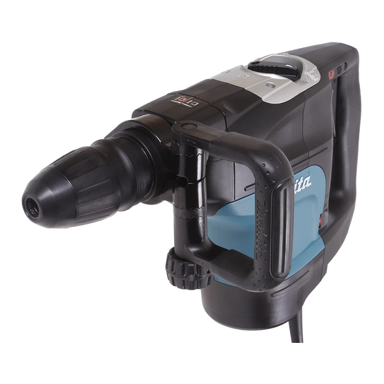
NEW TOOL
L
H
W
HR4501C
HR4511C
Max. Output (W)
Output
600
600
600
600
600
HR4511C
8.5 (18.7)
P 1/ 23
HR4510C
1,600
1,600
1,700
1,700
1,700
Advertisement
Table of Contents

Related Manuals for Makita HR4501C


Summary of Contents for Makita HR4501C
- Page 1 Model No. HR4501C, HR4510C, HR4511C Description Rotary Hammers 45mm (1-3/4") ONCEPT AND MAIN APPLICATIONS HR4501C series models have been developed as successor models of HR4500C, featuring low vibration level and high work efficiency. Listed below are their main features. HR4510C HR4501C...
-
Page 2: Necessary Repairing Tools
[2] LUBRICATION Apply the following lubricants to protect parts and product from unusual abrasion: *Makita grease N No. 2 (Part No. 181573-3: Grease vessel 93g) with white triangle *Makita grease R. No.00 (Part No. 181490-7: Hammer grease 30g) with black triangle Barrel and Tool holder section Item No. - Page 3 P 3/ 23 epair [2] LUBRICATION (cont.) Crank housing and Motor section Item No. Description Grease Portion to lubricate Amount Straight bevel gear 35 Gear teeth a little O Ring 27 on Striker Whole portion Cylinder 34 Inside between Striker and Piston Connecting rod Hole for Crank shaft pin O Ring 27 on Piston...
-
Page 4: Chuck Section
P 4/ 23 epair [3] DISASSEMBLY/ASSEMBLY [3] -1. Chuck Section DISASSEMBLY 1) Disassemble Handle section. (Fig. 4) Hold the machine upright and disassemble Chuck section in the order of Figs. 5 to 11. Fig. 4 Fig. 5 1. Separate Handle section from Motor housing by unscrewing 5x25 Tapping screws. - Page 5 P 5/ 23 epair [3] DISASSEMBLY/ASSEMBLY [3] -1. Chuck Section (cont.) DISASSEMBLY Fig. 8 Fig. 9 Tool holder Tool holder Chuck ring Chuck ring Tool retainer Release cover Release cover Ring spring 25 Remove another Ring spring 25 from Remove Chuck ring and Release cover. Tool holder.
- Page 6 P 6/ 23 epair [3] DISASSEMBLY/ASSEMBLY [3] -2. Tool Holder Section DISASSEMBLY 1) Disassemble Chuck section. (Figs. 4 - 11) 2) Disassemble the Tool holder section in the order of Figs. 13 -17. Fig. 13 Fig. 14 Fig. 15 Unscrew M4x25 Hex socket head bolt Disassemble Barrel complete Separate Tool holder from Barrel and remove Barrel cover complete.
- Page 7 P 7/ 23 epair [3] DISASSEMBLY/ASSEMBLY [3] -2. Tool Holder Section (cont.) DISASSEMBLY 3) Parts assembled to Cylinder 34 are removed. (Fig. 18) Fig. 18 Lock sleeve O ring 53 and Lock sleeve are Driving sleeve O ring 53 removed from Driving sleeve. Straight bevel gear 35 Striker Cylinder 34...
- Page 8 P 8/ 23 epair [3] DISASSEMBLY/ASSEMBLY [3] -2. Tool Holder Section (cont.) ASSEMBLY 3) After installing Fluoride ring 28 on the groove of Impact bolt, the Ring is stretched and its edges are protruding from the groove. Correct the deformation as illustrated in Fig. 21. Fig.
- Page 9 P 9/ 23 epair [3] DISASSEMBLY/ASSEMBLY [3] -3. Barrel Complete DISASSEMBLY 1) Remove Barrel complete from the machine as illustrated in Figs. 13, 14 and 15. 2) Remove Ring spring 50 and Oil seal 35 as illustrated in Figs. 24 and 25. Fig .
- Page 10 P 10/ 23 epair [3] DISASSEMBLY/ASSEMBLY [3] -4. Active Dynamic Vibration Absorber (HR4510C and HR4511C only) DISASSEMBLY 1) Disassemble Chuck section. (Figs. 4 to 11) and remove Barrel cover complete and Barrel section. (Figs. 13 and 14) 2) Disassemble Active dynamic vibration absorber in the order of Figs. 27 to 30. Fig.
- Page 11 P 11/ 23 epair [3] DISASSEMBLY/ASSEMBLY [3] -4. Active Dynamic Vibration Absorber (HR4510C and HR4511C only) ASSEMBLY 1) Assemble Active dynamic vibration absorber. (Fig. 30) 2) Set Spring guide in place as illustrated in Fig. 31. 3) Mount Active dynamic vibration absorber on the both side of Crank housing complete. (Fig. 32) 4) Do the reverse step of disassembly in Fig.
- Page 12 Fig. 36. 4) Mode change mechanism has to be assembled in Rotation with hammering mode as illustrated in Fig. 37, and Fig. 38 (for HR4511C) / 38A (for HR4501C and HR4510C) in the next page. Fig. 37...
- Page 13 5) After assembling Spring guide, mount Crank cap section. (Fig. 38: HR4511C only) 5A) Assemble Control plate by fitting its elliptic Loop portion with the protrusion of Crank lever. Then mount Crank cap cover. (Fig. 38A: HR4501C and HR4510C only) Fig. 38: HR4511C only Fig.
- Page 14 P 14/ 23 epair [3] DISASSEMBLY/ASSEMBLY [3] -6. Crank section, Cylinder, Piston (cont.) DISASSEMBLY 3) Disassemble Cylinder 34 as illustrated in Fig. 40. Fig. 40 Set Repairing jigs as follows. Turn Handle clockwise. Cylinder 34 gripped with 1R213's claw is pulled out from Crank housing complete. 1R213 Ring 38 is left in Crank housing complete after removal of Cylinder 34.
- Page 15 [3] -7. Switches, Controller, Power Supply Cord DISASSEMBLY 1) Main switch and Slide switch (for HR4501C and HR4510C only) can be disassembled as illustrated in Figs. 46 and 47. Fig. 46 Disassemble Handle Main switch can be...
-
Page 16: Motor Section
P 16/ 23 epair [3] DISASSEMBLY/ASSEMBLY [3] -7. Switches, Controller, Power Supply Cord (cont.) 3) Controller and Power supply cord can be disassembled as illustrated in Figs. 48 and 49. Fig. 48 Fig. 49 Power supply cord Lever up Controller's tabs Controller Controller with slotted screwdrivers. - Page 17 P 17/ 23 epair [3] -8. Motor Section (cont.) DISASSEMBLY 4) Disconnect Carbon brush from Armature's commutator. (Figs. 53) 5) Regarding HR4510C and HR4511C, remove Active Dynamic Vibration Absorber before separating Motor housing from Crank housing complete. (Fig. 54) Armature can be disassembled as illustrated in Fig. 55. Fig.
-
Page 18: Gear Section
P 18/ 23 epair [3] DISASSEMBLY/ASSEMBLY [3] -9. Gear Section DISASSEMBLY 1) Disassemble the following parts from Crank housing complete. * Chuck section (Figs. 4 to 11) * Barrel section (Figs. 13 and 14) * Handle section and Controller (Figs. 46 to 48) * Motor section (Figs. - Page 19 P 19/ 23 epair [3] DISASSEMBLY/ASSEMBLY [3] -10. Handle Section (HR4511C: with Vibration absorbing handle) DISASSEMBLY 1) Vibration absorbing handle consists of the following main parts. * Handle base * Dust cover and Dust cover support * Compression spring 11 (functions as a Vibration absorber) * Handle with Handle cover 2) Disassemble in the order from Figs.
-
Page 20: Fastening Torque
P 20/ 23 epair [3] DISASSEMBLY/ASSEMBLY [3] -11. Fastening Torque Fasten the bolts to the fastening torque listed in Fig. 63. Note: Apply adhesive (ThreeBond 1342 or Loctite 242) to the thread of M4x12 Pan head screw (Item No. 78). Fig. -
Page 21: Circuit Diagram
P 21/ 23 ircuit diagram Fig. D-1 Model HR4511C without Lock ON Switch Main Switch Color index of lead wires' sheath (ON / OFF Switch) Black White Controller is connected directly to Brush holder unit which is assembled to Field. Handle Lead wire of A is blue Motor... - Page 22 P 22/ 23 ircuit diagram Models HR4501C and HR4510C with Lock ON Switch Fig. D-3 Color index of lead wires' sheath Main Switch Black Lock ON Switch (ON / OFF Switch) White Handle Controller is connected directly to Brush holder unit which is assembled to Field.
- Page 23 P 23/ 23 iring diagram Connecting Carbon Brush Fig. D-5 Correct Connecting Rear cover side Wire connecting Pigtail from Carbon brush portion Terminal of Rear cover side Brush holder unit Armature shaft Connector Carbon brush Brush holder unit Motor housing Field side Connect Carbon brushe's Connector to Brush holder unit facing the wire connecting portion to Rear cover side.