Table of Contents
Advertisement
Quick Links
Advertisement
Table of Contents

Related Manuals for Makita AN935H


Summary of Contents for Makita AN935H
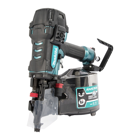
- Page 1 INSTRUCTION MANUAL Construction Coil Nailer AN935H Read before use.
-
Page 2: Specifications
SPECIFICATIONS Model: AN935H Air pressure 1.28 - 2.26 MPa (12.8 - 22.6 bar) Nail length Wire-collated coil nail 45 mm - 90 mm Sheet-collated coil nail 45 mm - 75 mm Nail capacity Wire-collated coil nail 120 pcs - 300 pcs... - Page 3 Personal protective equipments Always check contact element as instructed in this manual. Fasteners may be driven acci- dentally if the safety mechanism is not working correctly. Loading fasteners Do not load the tool with fasteners when any one of the operating controls is activated. Use only fasteners specified in this manual.
-
Page 4: Parts Description
Keep the tool in tip-top condi- tion. Lubricate moving parts to prevent rusting and minimize friction-related wear. Wipe off all dust from the parts. Ask Makita authorized service center for peri- 1. Nailing frequency (times/min) 2. Compressor air odical inspection of the tool. output per minute (L/min) 3. 2.26 MPa (22.6 bar) 4. 1.77 To maintain product SAFETY and RELIABILITY, MPa (17.7 bar) 5. -
Page 5: Functional Description
The air compressor must comply with the requirements FUNCTIONAL of EN60335-2-34. DESCRIPTION Select a compressor that has ample pressure and air output to assure cost-efficient operation. The graph shows the relation between nailing frequency, applica- ble pressure and compressor air output. CAUTION: Before adjusting or checking func- Thus, for example, if nailing takes place at a rate of tion on the tool, always lock the trigger by turning approximately 40 times per minute at a compression of the trigger lock lever to the lock position , and 1.77 MPa (17.7 bar), a compressor with an air output... - Page 6 ► 1 . Hook ► 1 . Nose adapter 2. Contact element 3. Protrusion 4. Recessed part Furthermore, this hook can be installed on either side of the tool. Air duster To change the installation position, remove the bolt with a hex wrench. Install the hook on another side and then secure it firmly with the bolt. CAUTION: Do not aim the ejection port of the air duster to someone.
-
Page 7: Loading Nailer
Then place the first nail in the nail rail and the second Loading nailer nail in the feed claw. Also, place other uncoiled nails on feeder body. CAUTION: Do not use deformed nails or linked sheet. Disconnect the air hose. Depress the latch lever and open the door and magazine cap. ► 1 . Nail rail 2. Feed claw Check that the nail coil is set properly in the magazine. Close the magazine cap carefully. Then with depressing the latch lever, close the door until the latch lever locks. -
Page 8: Operation
The trigger for single sequential actuation mode is factory-installed. To change the nailing mode to contact actuation, replace the trigger part with the one for con- tact actuation. ► 1 . Trigger for contact actuation 2. Silver part 3. Trigger for single sequential actuation 4. Black part Turn the trigger lock lever to the lock position ► 1 . Hinged part 2. Rod of the valve Insert the pin to the hole and secure it by urethane washer. Connect the air hose, and make sure that the tool operates properly. Refer to the section “Checking proper action before operation”. NOTE: To set back to single sequential actuation, follow the procedures for changing the trigger above. - Page 9 Single sequential actuation — Make sure that the tool does not operate only by placing the contact element against the workpiece Place the contact element against the workpiece and without pulling the trigger. pull the trigger fully. After nailing, release the contact element, and then release the trigger. ► 1 . Contact element 2.
- Page 10 Nailing on steel plate Nailing on concrete WARNING: WARNING: When nailing on the C-shaped Use hardened nails only for con- steel, limit the thickness to 3.2 mm (1/8") or thin- crete. Using other purposed nails may cause serious ner. Otherwise the tool will bounce severely and a injuries.
-
Page 11: Maintenance
MAINTENANCE CAUTION: Before attempting to perform inspection or maintenance, always lock the trig- ger by turning the trigger lock lever to the lock position , and disconnect the air hose from the tool. NOTICE: Never use gasoline, benzine, thinner, alcohol or the like. Discoloration, deformation or cracks may result. -
Page 12: Optional Accessories
OPTIONAL ACCESSORIES CAUTION: These accessories or attachments are recommended for use with your Makita tool specified in this manual. The use of any other accessories or attachments might present a risk of injury to persons. Only use accessory or attachment for its stated purpose. If you need any assistance for more details regard- ing these accessories, ask your local Makita Service ► 1 .