Table of Contents
Advertisement
Quick Links
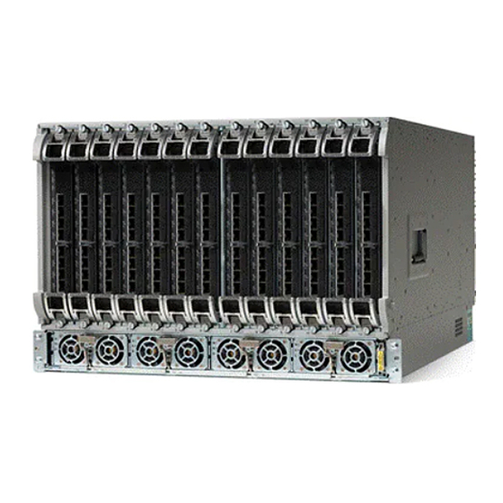
Installing the Cisco Remote PHY Shelf 7200
•
•
•
•
•
Installing the Chassis
The Cisco Remote PHY Shelf 7200 can be either mounted on the rack at the front or in the middle. Also, the
router can be either mounted on a standard 19-inch wide four-post equipment rack unit or a two-post rack
unit.
Note
The Cisco Remote PHY Shelf 7200 fully configured system can weigh up to 271 lbs, components must be
removed from the chassis to make the chassis lighter for rack installation. Remove all front power modules
and front RPD cards for rack mounting to reduce the weight. The PIC cards and Fan Tray can remain in the
system during rack mounting. For instructions on how to remove the components, see the monitoring sections.
Make sure that you place the cards and modules in an anti-static bag until you install the chassis in the rack.
Proceed with the installation if you have already unpacked your chassis and read all the site requirements for
your new equipment.
Required Tools and Equipment
• ESD-preventive wrist strap
• #2 Phillips torque screwdriver
• Flat-head screwdriver
Verifying Rack Dimensions
Before you install the chassis, measure the space between the vertical mounting flanges (rails) on your
equipment rack to verify that the rack conforms to the measurements shown in the following figure.
Installing the Chassis, on page 1
Installing the Fan Tray, on page 18
Installing the Power Shelf, on page 23
Installing the Cisco Remote PHY Shelf 7200 PIC, on page 30
Installing the RPDs, on page 32
Installing the Cisco Remote PHY Shelf 7200
1
Advertisement
Table of Contents

Related Manuals for Cisco Remote PHY Shelf 7200


Summary of Contents for Cisco Remote PHY Shelf 7200
- Page 1 Installing the Chassis The Cisco Remote PHY Shelf 7200 can be either mounted on the rack at the front or in the middle. Also, the router can be either mounted on a standard 19-inch wide four-post equipment rack unit or a two-post rack unit.
- Page 2 Installing the Cisco Remote PHY Shelf 7200 Installing the Chassis Installation Brackets Figure 1: Verifying Equipment Rack Dimensions Step 1 Mark and measure the distance between two holes on the left and right mounting rails. The distance should measure 18.31 inches ± 0.06 inches (46.5 cm ± 0.15 cm).
-
Page 3: Attaching The Chassis Rack-Mount Brackets
Installing the Cisco Remote PHY Shelf 7200 Attaching the Chassis Rack-Mount Brackets Figure 2: Chassis Installation Bracket Chassis Installation Bracket After you install the chassis and secure it to the rack, remove the chassis installation brackets from the rack. Note The chassis does not need these brackets for supporting the weight, after all rack mount screws are secured. - Page 4 • Front Rack-Mounting the system: The chassis is shipped with the rack-mount brackets installed in the front. Proceed to Installing the Cisco Remote PHY Shelf 7200 in a Rack, on page • Mid Rack-Mounting the system: Install the mounting bracket in the middle of the chassis, so that you can recess the chassis in the rack or install the chassis in a two-post rack unit.
- Page 5 Installing the Cisco Remote PHY Shelf 7200 Installing the Cisco Remote PHY Shelf 7200 in a Rack Figure 4: Installing rack-mount brackets mid mount Step 4 Repeat the steps 1, 2, and 3 on the other side of the chassis.
- Page 6 Installing the Cisco Remote PHY Shelf 7200 Installing the Cisco Remote PHY Shelf 7200 in a Four-Post Rack Warning To prevent physical injury when mounting or servicing this unit in a rack, you must take special precautions to ensure that the system remains stable. The following guidelines are provided to ensure your safety: •...
- Page 7 Installing the Cisco Remote PHY Shelf 7200 Installing the Cisco Remote PHY Shelf 7200 in a Four-Post Rack Step 5 Position the chassis until the rack-mounting flanges are flush against the mounting rails on the rack. Installing the Cisco Remote PHY Shelf 7200...
- Page 8 Installing the Cisco Remote PHY Shelf 7200 Installing the Cisco Remote PHY Shelf 7200 in a Four-Post Rack Step 6 Hold the chassis in position against the mounting rails and do the following: a) Insert a bottom screw into the rack mount ear on each side and use a hand-held screwdriver to tighten the screw to the rack rail.
- Page 9 Installing the Cisco Remote PHY Shelf 7200 in a Two-Post Rack You can install the Cisco Remote PHY Shelf 7200 in a two-post 19-inch (48.26 cm) rack either as a front mount or a mid-mount if the spacing between rails is at least 17.70 inches (44.96cm) wide. If the rack rail opening is narrower than this you can only use the mid mount option for mounting the chassis into the two post rack.
- Page 10 Installing the Cisco Remote PHY Shelf 7200 Installing the Cisco Remote PHY Shelf 7200 in a Two-Post Rack Step 7 Hold the chassis in position against the mounting rails and do the following: a) Insert a bottom screw into the rack mount ear on each side and use a hand-held screwdriver to tighten the screw to the rack rail.
-
Page 11: Attaching The Cable-Management Bracket
Installing the Cisco Remote PHY Shelf 7200 Attaching the Cable-Management Bracket Step 8 Ensure that all screws on each of the side rack-mount brackets are tightened to the equipment rack before the chassis installation bracket is removed from the rack. - Page 12 Installing the Cisco Remote PHY Shelf 7200 Attaching the Cable-Management Bracket Note The chassis will not fit through a 19-inch rack rail opening with the cable management system pre-installed. Complete the following steps to install the Cable-Management Bracket: 1. Install the chassis into the rack.
- Page 13 4. Repeat steps 1-3 for the right side RF management bracket. The Cisco Remote PHY Shelf 7200 has 216 ports, and the coax cable routing was designed for half the cables that are routed to either side of the system.
-
Page 14: Attaching A Chassis Ground Connection
Installing the Cisco Remote PHY Shelf 7200 Attaching a Chassis Ground Connection Cables from PIC0 Cables from PIC1 Cables from PIC2 Cables from PIC3 Cables from PIC4 Cables from PIC5 Attaching a Chassis Ground Connection Before you begin Warning This equipment must be grounded. Never defeat the ground conductor or operate the equipment in the absence of a suitably installed ground conductor. - Page 15 Installing the Cisco Remote PHY Shelf 7200 Attaching a Chassis Ground Connection Caution The grounding wire is always the first to be installed or connected and the last to be removed or disconnected. Required Tools and Equipment • Phillips Screwdriver •...
- Page 16 Installing the Cisco Remote PHY Shelf 7200 Installing the Optical Cable Management Kit (Optional) Installing the Optical Cable Management Kit (Optional) To install the optional Optical Cable Management (OCMG) Kit, complete the following steps: 1. Remove the top two screws from the power shelf flange ears. Keep the screws safe.
- Page 17 Installing the Cisco Remote PHY Shelf 7200 Installing the Optical Cable Management Kit (Optional) 3. Install the right and left cable management support brackets onto the power shelf flanges as shown in the following image. Secure the bracket with four T15 Torx screws. Tighten to 6-8 Lb-In torque.
-
Page 18: Installing The Fan Tray
Air is expelled from the rear of the chassis. The keep-out areas are defined to ensure adequate space around the Cisco Remote PHY Shelf 7200 chassis. The space is necessary to ensure adequate air intake and exhaust. The figure shows the keep-out areas for the Cisco Remote PHY Shelf 7200 chassis. - Page 19 Installing the Cisco Remote PHY Shelf 7200 Installing the Fan Tray Figure 6: Allow keep-Out Areas for the Cisco Remote PHY Shelf 7200 Chassis The Cisco Remote PHY Shelf 7200 Fan Tray is a Field Replaceable Unit without Fans. Installing the Cisco Remote PHY Shelf 7200...
- Page 20 Installing the Cisco Remote PHY Shelf 7200 Installing the Fan Tray Restrictions • Do not boot the chassis unless all the Fan Modules are installed. • Only one fan module should be removed at a time for servicing or replacement.
- Page 21 Using only one ejector for Fan Tray installation could cause damage to the Fan Tray connector. Step 4 Secure the 4 mounting screws on the Cisco Remote PHY Shelf 7200 Fan Tray to the chassis. Torque to 8 Lb-In. Fan Tray Screws...
-
Page 22: Installing The Fan Module
Installing the Cisco Remote PHY Shelf 7200 Installing the Fan Module The Cisco Remote PHY Shelf 7200 system should not be operating without a Fan Tray installed for more than Note 1-2 minutes or the system could experience thermal events, alarms, and potentially trip thermal protections that would shut down RPD cards. -
Page 23: Installing The Power Shelf
Installing the Cisco Remote PHY Shelf 7200 Installing the Power Shelf 3. Ensure that the top and bottom Fan Module latches are engaged on every fan module to the fan tray sheetmetal bay. Installing the Power Shelf The chassis ships with an AC or DC Power Shelf installed depending on the configuration. In the future you may need to install a new Power Shelf or to swap the power system of the chassis. - Page 24 Installing the Cisco Remote PHY Shelf 7200 Installing the Power Shelf Warning When you install the module, the chassis ground connection must always be made first and disconnected last. Statement 1046 • Be aware of the weight and size of the equipment. Handle it with care.
- Page 25 Installing the Cisco Remote PHY Shelf 7200 Installing the Power Shelf Figure 8: Removing the Front Power Shelf from the Chassis 4X AC or DC Power Modules Power Shelf Ejectors Power Shelf T15 Securing Screws Step 5 Loosen and remove the four T15 screws on the front power shelf chassis mounting ears using a T15 torx screwdriver.
- Page 26 Installing the Cisco Remote PHY Shelf 7200 Connecting Power to the AC-Powered Cisco Remote PHY Shelf 7200 Step 6 Use the two Power Shelf ejectors to eject the Power Shelf from the chassis. Note The Power Shelf to Power Modules are keyed AC modules to the AC Shelf and DC modules to the DC Shelf...
- Page 27 Installing the Cisco Remote PHY Shelf 7200 Connecting Power to the AC-Powered Cisco Remote PHY Shelf 7200 chamfers in the upper corners, which are used to distinguish them as rated for 155C instead of the typical 70C used on the C19/C20.
- Page 28 The terminal block covers are an integral part of the safety design of the product. Do not operate the unit without the covers installed. Statement 1077 Warning Before connecting DC Power to theCisco Remote PHY Shelf 7200 DC Power Shelf, the ground connection must always be made first and disconnected last. Warning Before performing any of the following procedures, ensure that power is removed from the DC circuit.
- Page 29 Installing the Cisco Remote PHY Shelf 7200 Connecting Power to the DC-Powered Cisco Remote PHY Shelf 7200 leads, source DC (-) and source DC return (+), can be used for each DC Power Module. These cables are available from any commercial cable vendor. All input power cables for the chassis must have the same wire gauge.
- Page 30 Installing the Cisco Remote PHY Shelf 7200 PIC Note The Cisco Remote PHY Shelf 7200 PIC should be handled gently and carefully, to avoid damage to the RF connectors. Complete the following steps to install the Cisco Remote PHY Shelf 7200: 1.
- Page 31 Installing the Cisco Remote PHY Shelf 7200 Installing the Connectors into the PIC Connector Latches 5. Install the RF cables into the port holes of the RF PIC. The recommended cables and connectors to be used with the PIC cards are listed in the following table:...
- Page 32 Installing the Cisco Remote PHY Shelf 7200 Installing the RPDs Figure 9: Installing the connector into the PIC connector latches 2. Gently wiggle and push the connector into the panel port hole. 3. The latch will snap closed when the connector is fully seated.
- Page 33 Installing the Cisco Remote PHY Shelf 7200 Installing the RPDs 2. Gently slide the RPD into the chassis. Ensure that there is no binding of the card during installation. 3. Actuate the two ejectors together to finish the connector engagement of the RPD to the chassis.
-
Page 34: Installing The Air Filter
Installing the Cisco Remote PHY Shelf 7200 Installing the Air Filter Installing the Air Filter Required Tools and Equipment • Air filter for the line card • ESD-preventive Wrist Strap Note Attach an ESD-preventive wrist strap to your wrist and connect its end to the grounding lug that is connected to the chassis.