Cisco SCE8000 Installing
Hide thumbs
Also See for SCE8000:
- Configuration manual (262 pages) ,
- Installation and configuration manual (248 pages) ,
- Installation manual (51 pages)
Table of Contents
Advertisement
Quick Links
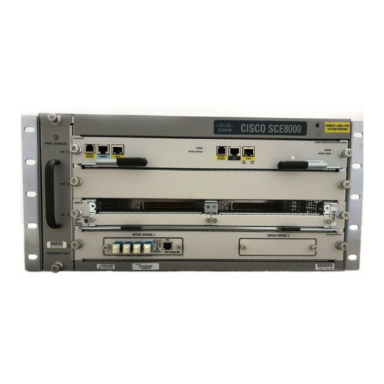
Installing the Cisco SCE8000 Chassis
Revised: November 8, 2010, OL-21054-04
Introduction
This chapter describes how to install a Cisco SCE8000 chassis.
Only trained and qualified personnel should be allowed to install, replace, or service this equipment.
Warning
Statement 1030
Warning
There is the danger of explosion if the battery is replaced incorrectly. The battery is not a
user-serviceable part.
Statement 1015
Warning
Class 1 laser product.
Statement 1008
Because invisible laser radiation may be emitted from the aperture of the port when no cable is
Warning
connected, avoid exposure to laser radiation and do not stare into open apertures.
Statement 1056
Blank faceplates and cover panels serve three important functions: they prevent exposure to
Warning
hazardous voltages and currents inside the chassis; they contain electromagnetic interference (EMI)
that might disrupt other equipment; and they direct the flow of cooling air through the chassis. Do not
operate the system unless all cards, faceplates, front covers, and rear covers are in place.
Statement 1029
Before you install, operate, or service the system, read the
Note
Information for the Cisco SCE8000
should know before working with the system.
OL-21054-04
C H A P T E R
Regulatory Compliance and Safety
Platform. This guide contains important safety information you
Cisco SCE8000 10GBE Installation and Configuration Guide
4
4-1
Advertisement
Table of Contents

Related Manuals for Cisco SCE8000


Summary of Contents for Cisco SCE8000
- Page 1 C H A P T E R Installing the Cisco SCE8000 Chassis Revised: November 8, 2010, OL-21054-04 Introduction This chapter describes how to install a Cisco SCE8000 chassis. Only trained and qualified personnel should be allowed to install, replace, or service this equipment. Warning Statement 1030 Warning There is the danger of explosion if the battery is replaced incorrectly.
-
Page 2: Preparing For Installation
Preparing for Installation, page 4-2 • Installing the Cisco SCE8000 Chassis in the Rack, page 4-14 • Connecting the System Ground, page 4-19 • Installing the Power Supplies in the Cisco SCE8000 Chassis, page 4-20 • Preparing for Installation Safety, page 4-2 • •... -
Page 3: Site Requirements
Chapter 4 Installing the Cisco SCE8000 Chassis Site Requirements Site Requirements This section provides site power requirements for the Cisco SCE8000 chassis. Verify the site power before installation. • Preventing Electrostatic Discharge Damage, page 4-3 • Environmental Requirements, page 4-3 •... -
Page 4: Power Requirements
• failures at your site. Avoid UPS types that use ferroresonant technology. These UPS types can become unstable with systems like the Cisco SCE8000, which can have substantial current draw fluctuations because of bursty data traffic patterns. Cisco SCE8000 10GBE Installation and Configuration Guide... -
Page 5: Power Connection Guidelines
Chapter 4 Installing the Cisco SCE8000 Chassis Power Connection Guidelines Power Connection Guidelines This section provides the guidelines for connecting the Cisco SCE8000 AC and DC power supplies to the site power source. • AC-Powered Systems, page 4-5 • DC-Powered Systems, page 4-11 •... - Page 6 AC-input frequency rating 50/60 Hz (nominal) (±3% for full range) Table 4-4 lists the AC-input power cord options, specifications, and Cisco product numbers for the 2700 W AC-input power supplies. It also references power cord illustrations. Table 4-4 AC-Input Power Cord Options...
- Page 7 *The PDU power cable is designed for users who power their switch from a PDU. The end of the cable that plugs into the Cisco SCE8000 chassis has a C19 connector; the other end of the cable that plugs into the PDU has a C20 connector.
- Page 8 Chapter 4 Installing the Cisco SCE8000 Chassis AC-Powered Systems Figure 4-2 CAB-AC16A-CH= Cordset rating: 16A, 250V Length: 14 ft 0 in. (4.26 m) Plug: GB16C Connector: IEC 60320-1 C19 Figure 4-3 CAB-AC-2500W-EU= Cordset rating: 16 A, 250 V Length: 14 ft 0 in. (4.26 m)
- Page 9 Chapter 4 Installing the Cisco SCE8000 Chassis AC-Powered Systems Figure 4-5 CAB-AC-2500W-ISRL= Cordset rating: 16 A, 250 V Length: 14 ft 0 in. (4.26 m) Plug: SI16S3 Connector: IEC 60320 C19 Figure 4-6 CAB-AC-2500W-US1= Figure 4-7 CAB-AC-C6K-TWLK= Cisco SCE8000 10GBE Installation and Configuration Guide...
- Page 10 Chapter 4 Installing the Cisco SCE8000 Chassis AC-Powered Systems Figure 4-8 CAB-7513AC= Cordset rating: 20 A, 125 V Plug: NEMA 5-20 Length: 14 ft 0 in. (4.26 m) Connector: IEC 60320 C19 Figure 4-9 CAB-7513ACSA= Cordset rating: 16 A, 250 V Length: 14 ft 0 in.
-
Page 11: Dc-Powered Systems
The DC supplies each have the provision for a dual connection to the power source in order to permit • high-power operation without exceeding current ratings. For the SCE8000, it is not necessary to connect both of these inputs to DC power sources; it is sufficient to connect only the '1' connections. - Page 12 The DC supplies each have the provision for a dual connection to the power source in order to permit Note high-power operation without exceeding current ratings. For the Cisco SCE8000, it is not necessary to connect both of these inputs to DC power sources; it is sufficient to connect only the '1' connections.
-
Page 13: Site Planning Checklist
Chapter 4 Installing the Cisco SCE8000 Chassis Site Planning Checklist Site Planning Checklist Table 4-6 lists the site planning activities that you should perform before installing the Cisco SCE8000 chassis. Completing each activity helps ensure a successful installation. Table 4-6 Site Planning Checklist Task No. -
Page 14: Installing The Cisco Sce8000 Chassis In The Rack
Do not discard the shipping container when you unpack the Cisco SCE8000. Flatten the shipping cartons and store them with the pallet. You need these containers to move or ship the Cisco SCE8000. Perform the following to check the contents of the shipping container: •... -
Page 15: Required Tools
Depth of the rack, measured between the front and rear mounting strips, must be at least 19.25 in (48.9 cm) but not more than 32 in (81.3 cm). Rack must have sufficient vertical clearance to insert the chassis. The height of the Cisco SCE8000 •... -
Page 16: Installing The Chassis Brackets
Chapter 4 Installing the Cisco SCE8000 Chassis Installing the Chassis Brackets Installing the Chassis Brackets The chassis is shipped with the mounting brackets installed on the front of the chassis. These brackets can be installed on the rear of the chassis. - Page 17 Chapter 4 Installing the Cisco SCE8000 Chassis Installing the Chassis in the Rack To install the Cisco SCE8000 chassis in the equipment rack, perform these steps: Position the chassis in the rack as follows: Step 1 If the front of the chassis (front panel) is at the front of the rack, insert the rear of the chassis between •...
-
Page 18: Installing An Optical Bypass Module
Installing an Optical Bypass Module There are two installation options for the external bypass modules: Chassis mount panel—This panel is mounted on slot 4 of the Cisco SCE8000 chassis. It hosts two • optical bypass modules, which will serve the two traffic links supported by one Cisco SCE8000 chassis. -
Page 19: Connecting The System Ground
Connecting the System Ground Connecting the System Ground This section describes how to connect a system (earth) ground to the Cisco SCE8000 chassis. Two threaded M4 holes are provided on the chassis frame to attach the ground cable. Connect the system ground on both AC- and DC-powered systems to an earth ground if this equipment Note is installed in a US or European Central Office. -
Page 20: Installing The Power Supplies In The Cisco Sce8000 Chassis
Cisco SCE8000 chassis. Installing the Power Supplies in the Cisco SCE8000 Chassis The Cisco SCE8000 chassis is shipped with the power supplies (AC or DC) already installed. Should it be necessary to install a power supply module, see the “Removing and Replacing the Power...