
Related Manuals for Target 5948307T


Summary of Contents for Target 5948307T
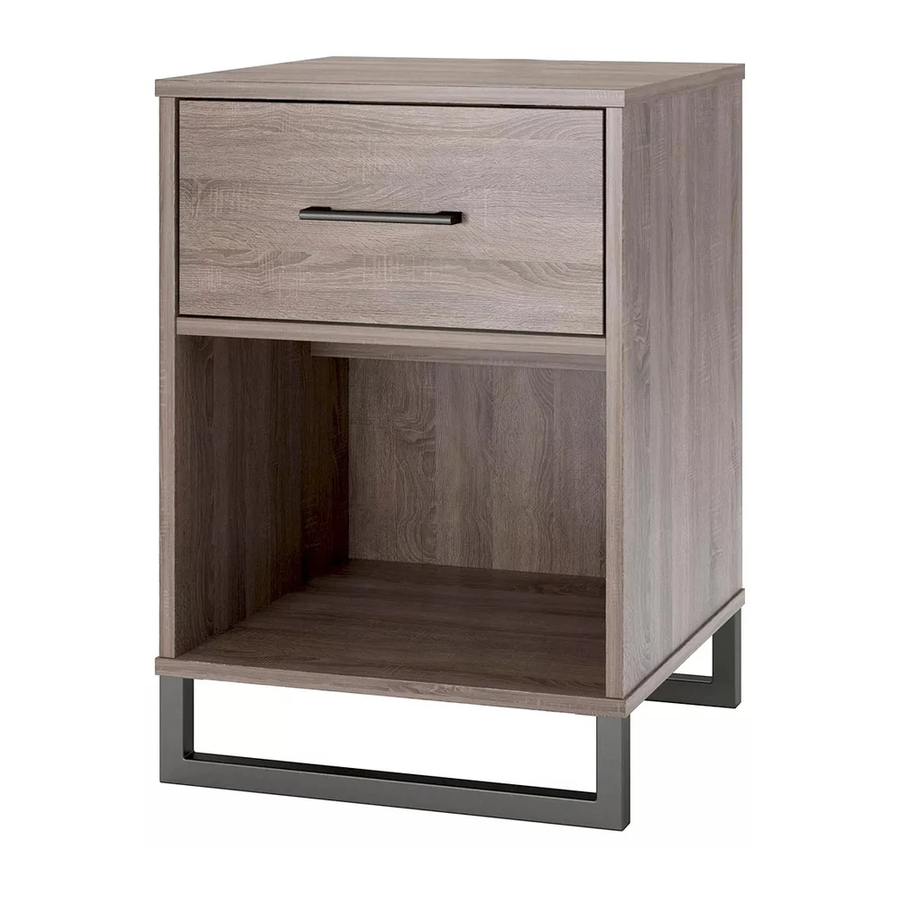
- Page 1 Mixed Material night stand style # 5948307T DPCI # 249-05-0492 >> assembly instructions B345948307T 01...
- Page 2 Congratulations on your latest Target purchase. Now what? Don't start sweating over the box of parts. This will be easy. We did the hard work for you. All you need to do is follow our simple instructions and you'll be on your way to transforming your room in no time.
- Page 3 table of contents introduction hardware parts list how to use the cam lock system assembly 7-22 Just call 1-855-MYTGTHOME (855-698-4846) for parts and service. For faster service, have the style number and DPCI number QUESTIONS? ready when calling.
- Page 4 hardware (4) x4 (1) x8 (2) x8 (3) x10 (6) x16 (5) x21 cam lock cam bolt wood dowel nail #8x1- " flat head screw " pan head screw #A22570 #A22510 #A21660 #A21110 #A13410 #A12120 (10) x2 (7) x4 (8) x10 (9) x2 drawer bracket #6x1-...
- Page 5 Parts shown are the base cabinet of your model. Please note, most parts are labeled with a sticker or have a letter stamped on a raw edge. Parts List Part F may not be labeled. ITEM PART NUMBER DESCRIPTION 35948307010 LEFT PANEL 35948307020 RIGHT PANEL...
- Page 6 how to use the cam lock system Tighten to fully seat. Do not over tighten. Proper orientation of cam. ½ turn to fully lock. Lock...
- Page 7 step Proper orientation of CAM LOCK (8) x3 (1) x2 (2) x2 (3) x1 (12) x1 cam bolt wood dowel " screw cam lock left cabinet slide marked with an "L" 1. Screw-in cam bolts must be screwed down flush. 2.
- Page 8 step Proper orientation of CAM LOCK (8) x3 (2) x2 (1) x2 (12) x1 (3) x1 cam bolt cam lock right cabinet slide wood dowel " screw marked with an "R" 1. Screw-in cam bolts must be screwed down flush. 2.
- Page 9 step (2) x4 cam bolt 1. Screw-in cam bolts must be screwed down flush. 2. Refer to page 6 for instructions on how to use the cam lock system.
- Page 10 step Proper orientation of CAM LOCK (1) x4 (3) x8 cam lock wood dowel 1. Refer to page 6 for instructions on how to use the cam lock system.
- Page 11 step raw surface UNLOCK LOCK finished edge raw surface 1. In this step, make sure the Rear Upright (G) finished edge is up. 2. The finished surface of Rear Brace (F) is up. 3. Refer to page 6 for instructions on how to use the cam lock system.
- Page 12 step (4) x4 #8x1- " flat head screw 1. In this step, position the Bottom (D) so that the back edge is flush with back edge of Left Panel (A) / Right Panel (B).
- Page 13 step UNLOCK LOCK 1. Refer to page 6 for instructions on how to use the cam lock system.
- Page 14 step IMPORTANT! THE BACK PANELS ARE A STRUCTURAL PART OF THIS UNIT AND MUST BE INSTALLED PROPERLY. WARNING Please make sure that the Back Panel is attached securely. All nails must be driven into the parts straight and centered. Failure to do so could cause instability, product collapse, and/or serious injury.
- Page 15 step (6) x12 (13) x2 metal leg " pan head screw...
- Page 16 step Bracket Orientation Bracket Orientation (10) x2 drawer bracket 1. Lay the drawer sides down on a flat hard surface. Carefully line up the drawer bracket with the holes in the drawer side as shown. Using a hammer, tap each drawer bracket stem part way into each hole. Repeat this process until the drawer bracket is fully seated on the drawer side.
- Page 17 step line up all grooves during assembly (6) x4 " pan head screw...
- Page 18 step finished surface 1. Slide drawer bottom into grooves in drawer sides. Make sure finished surface is facing up.
- Page 19 step (7) x4 #6x1- " flat head screw...
- Page 20 step marked with an "L" marked with an "R" (12) x1 (11) x1 (9) x2 (8) x4 (12) x1 left drawer slide handle #6x7/16" flat head screw right drawer slide 8-32x " bolt...
- Page 21 step roller cabinet member drawer runner roller Notice, the drawer bracket holes are slotted. Drawer fronts can be adjusted by loosening screws, making needed adjustments and retightening screws.
- Page 22 MAXIMUM LOADS This unit has been designed to support the maximum loads shown. Exceeding these load limits could cause sagging, instability, product collapse, and/or serious injury. Warning: Risk of injury to persons - do not place a television on this furniture. This furniture is not approved for use with a television.
- Page 23 ©2017 Target. The Bullseye Design is a trademark of Target Brands inc. All rights reserved.