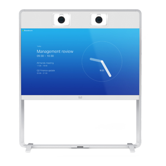
Cisco TelePresence MX700 Installation Manual
Single camera on a free standing floor stand or a floor stand secured to the wall
Hide thumbs
Also See for TelePresence MX700:
- Reference manual (241 pages) ,
- Administrator's manual (141 pages) ,
- Installation manual (32 pages)

Related Manuals for Cisco TelePresence MX700


Summary of Contents for Cisco TelePresence MX700
- Page 1 Installation guide for Cisco TelePresence MX700 Single Camera on a free standing floor stand or a floor stand secured to the wall 78-100218-03A0 | 2018 JUNE | © 2018 Cisco Systems, Inc. All rights reserved. https://www.cisco.com/go/mx-docs...
- Page 2 Use the first link if your device is registered to the Cisco Webex service and the second link if the device is registered to another service. Floor stand secured to the wall 78-100218-03A0 | 2018 JUNE | ©...
- Page 3 Lay the box marked with A, and B+C+E+K flat on the floor. Remove the lid. Boxes B, C, E and K are inside. F-J+ L+M B+C+E+K 78-100218-03A0 | 2018 JUNE | © 2018 Cisco Systems, Inc. All rights reserved. Page 3...
- Page 4 Tool: Allen key, 4 mm PT4x10, pan Tool: Torx T20 M4x8, pan Tool: Allen key, 2.5 mm Allen key, 4 mm Allen key, 2.5 mm Torx T20 78-100218-03A0 | 2018 JUNE | © 2018 Cisco Systems, Inc. All rights reserved. Page 4...
- Page 5 Remove covers from floor stand parts Set aside the covers. They will be replaced when the system is fully assembled and tested (step 20). Front 78-100218-03A0 | 2018 JUNE | © 2018 Cisco Systems, Inc. All rights reserved. Page 5...
- Page 6 8 × M6x12, first on one side; then on the other. countersunk Six screws from the back and two from the top. 8 × M6x12, countersunk 78-100218-03A0 | 2018 JUNE | © 2018 Cisco Systems, Inc. All rights reserved. Page 6...
- Page 7 Installation guide for Cisco TelePresence MX700 Single camera - Floor stand Fasten center bracket 2 × M6x12, pan Front 78-100218-03A0 | 2018 JUNE | © 2018 Cisco Systems, Inc. All rights reserved. Page 7...
- Page 8 Mount the feet to the floor stand to allow it to be free standing Option B (secured to the wall) is described on the next page. 4 × M6x35, countersunk Front 78-100218-03A0 | 2018 JUNE | © 2018 Cisco Systems, Inc. All rights reserved. Page 8...
- Page 9 94 mm / 3.70 in. 37 mm / 1.46 in. Fasten the floor stand to the wall brackets with the 4 × M6x12, pan four screws (provided). Side view 78-100218-03A0 | 2018 JUNE | © 2018 Cisco Systems, Inc. All rights reserved. Page 9...
- Page 10 78-100218-03A0 | 2018 JUNE | © 2018 Cisco Systems, Inc. All rights reserved. Page 10...
- Page 11 Tighten the wing nuts on both sides. They are accessed from the sides of the monitor. Front view Front view 78-100218-03A0 | 2018 JUNE | © 2018 Cisco Systems, Inc. All rights reserved. Page 11...
- Page 12 9. 4 × M6x35, countersunk Enter four screws from front and four screws from underneath. Then, tighten all screws. 78-100218-03A0 | 2018 JUNE | © 2018 Cisco Systems, Inc. All rights reserved. Page 12...
- Page 13 Front view Do not let go of the monitor before it is securely placed on the floor stand. Front view 78-100218-03A0 | 2018 JUNE | © 2018 Cisco Systems, Inc. All rights reserved. Page 13...
- Page 14 The socket must be reached from below. Make sure that the power switch next to the socket is in its ON position. 78-100218-03A0 | 2018 JUNE | © 2018 Cisco Systems, Inc. All rights reserved. Page 14...
- Page 15 Installation guide for Cisco TelePresence MX700 Single camera - Floor stand Remove support handles Unscrew the screws (4 × M4x8) and remove the support handles. 78-100218-03A0 | 2018 JUNE | © 2018 Cisco Systems, Inc. All rights reserved. Page 15...
- Page 16 Place the joining bracket in the channel. Make sure it aligns with the channel at top. Push down the lever to 7 × M6x12, pan horizontal position. 78-100218-03A0 | 2018 JUNE | © 2018 Cisco Systems, Inc. All rights reserved. Page 16...
- Page 17 Lead the guidance pins on the back cover into the holes. Lower the back cover toward the system. The cover snaps to magnets. 78-100218-03A0 | 2018 JUNE | © 2018 Cisco Systems, Inc. All rights reserved. Page 17...
- Page 18 HDMI (step 14) number 3–5 (step 17) USB, type B (step 14) Power (step 16) 5 × Loudspeaker cables Ethernet (step 16) number 1–5 (step 17) 78-100218-03A0 | 2018 JUNE | © 2018 Cisco Systems, Inc. All rights reserved. Page 18...
- Page 19 Connect cables to right monitor and PoE injector SWITCH Ethernet Power over Ethernet injector COLOR HDMI DO NOT CALIBRATION REMOVE HDMI USB (type B) Right monitor connector panel 78-100218-03A0 | 2018 JUNE | © 2018 Cisco Systems, Inc. All rights reserved. Page 19...
-
Page 20: Mount Camera
Fasten the stud to the top profile with one screw from above. Repeat this step for the left side. 78-100218-03A0 | 2018 JUNE | © 2018 Cisco Systems, Inc. All rights reserved. Page 20... - Page 21 2 × M4x8, pan Enter the camera cover in the clips at the bottom, and align it with the back panels. The cover snaps to magnets. 78-100218-03A0 | 2018 JUNE | © 2018 Cisco Systems, Inc. All rights reserved. Page 21...
- Page 22 Installation guide for Cisco TelePresence MX700 Single camera - Floor stand Connect camera cables DAISY VISCA CHAIN HDMI Power Ethernet Camera connector panel 78-100218-03A0 | 2018 JUNE | © 2018 Cisco Systems, Inc. All rights reserved. Page 22...
- Page 23 Enter the loudspeaker onto the speaker clip. Fasten with one screw. 8 × PT4x10 Make sure the cable is not pinched. (one for each loudspeaker) 78-100218-03A0 | 2018 JUNE | © 2018 Cisco Systems, Inc. All rights reserved. Page 23...
-
Page 24: Connect External Cables
CAT 5e, shielded Ethernet cable, 5 m. extension cord and country-specific cable. Codec connector panel Two presentation cables are provided: HDMI ↔ HDMI; and DVI/Euroblock ↔ VGA/mini jack. 78-100218-03A0 | 2018 JUNE | © 2018 Cisco Systems, Inc. All rights reserved. Page 24... - Page 25 The Ethernet socket is behind the lid at the rear of Touch 10. Use one of the provided PoE rated CAT 5e Ethernet cables, 12.5 or 4 m, flat. 78-100218-03A0 | 2018 JUNE | © 2018 Cisco Systems, Inc. All rights reserved. Page 25...
-
Page 26: Start Up The System
Started articles for room devices. Other services: For further information on set-up and configuration, download the Getting Started Guide from the Cisco web site, https://www.cisco.com/go/mx-docs 78-100218-03A0 | 2018 JUNE | © 2018 Cisco Systems, Inc. All rights reserved. Page 26... - Page 27 Installation guide for Cisco TelePresence MX700 Single camera - Floor stand Mount covers The top cover is fastened by clips. The other covers snap to magnets. 78-100218-03A0 | 2018 JUNE | © 2018 Cisco Systems, Inc. All rights reserved. Page 27...
- Page 28 Installation guide for Cisco TelePresence MX700 Single camera - Floor stand Mount textile grilles L, M Use the provided gloves when handling the textile grilles. The grilles snap to magnets. 78-100218-03A0 | 2018 JUNE | © 2018 Cisco Systems, Inc. All rights reserved. Page 28...
- Page 29 For a list of offices, visit the Cisco website at https://www.cisco.com/go/offices Cisco and the Cisco logo are trademarks or registered trademarks of Cisco and/or its affiliates in the U.S.and other countries. To view a list of Cisco trademarks, go to this URL: www.cisco.com/go/trademarks. Third-party trademarks mentioned are the property of their respective owners.