
Related Manuals for Feig Electronic OBID i-Scan ID ISC.ANT340/240-A


Summary of Contents for Feig Electronic OBID i-Scan ID ISC.ANT340/240-A
- Page 1 MONTAGE ® OBID i-scan INSTALLATION ID ISC.ANT340240 Padantenna (deutsch / english) final public (B) 2007-09-25 M10101-3de-ID-B.doc...
- Page 2 ® OBID i-scan Montage ID ISC.ANT340/240-A / -B deutsche Version ab Seite 3 english version from page 16 FEIG ELECTRONIC GmbH Seite 2 von 28 M10101-3de-ID-B.doc...
- Page 3 Hinweise jederzeit dankbar. Die in diesem Dokument gemachten Installationsempfehlungen gehen von günstigsten Rahmenbedingun- gen aus. FEIG ELECTRONIC GmbH übernimmt weder Gewähr für die einwandfreie Funktion in system- fremden Umgebungen, noch für die Funktion eines Gesamtsystems, welches die in diesem Dokument be- schriebenen Geräte enthält.
-
Page 4: Table Of Contents
Der Einfluss von Metall auf die Reichweite...............10 Das Messen des Stehwellenverhältnisses VSWR ............11 Der Verlauf der magnetischen Feldlinien der Antenne Technische Daten Zulassungen Europa (CE)........................14 USA (UL)........................14 Gerätevorschläge und mögliche Bezugsquellen : FEIG ELECTRONIC GmbH Seite 4 von 28 M10101-3de-ID-B.doc... -
Page 5: Sicherheits- Und Warnhinweise - Vor Inbetriebnahme Unbedingt Lesen
Obwohl dieses Gerät die zulässigen Grenzwerte für elektromagnetische Felder nicht über- schreitet, sollten Sie einen Mindestabstand von 25 cm zwischen dem Gerät und Ihrem Herz- schrittmacher einhalten und sich nicht für längere Zeit in unmittelbarer Nähe des Geräts bzw. der Antenne aufhalten. FEIG ELECTRONIC GmbH Seite 5 von 28 M10101-3de-ID-B.doc... -
Page 6: Leistungsmerkmale Der Antenne
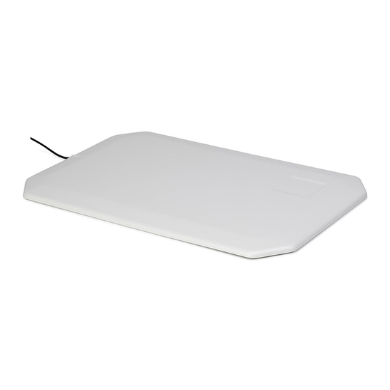
Folgende Varianten der Antenne sind derzeit erhältlich Bezeichnung Variante Bestellnummer ID ISC.ANT340/240-A mit ABS Gehäuse 1663.000.00.00 ID ISC.ANT340/240-B ohne Gehäuse 2396.000.00.00 Hinweis Im Lieferumfang sind 1 Stück Antenne inklusive Anschlusskabel und eine Montageanlei- tung enthalten. FEIG ELECTRONIC GmbH Seite 6 von 28 M10101-3de-ID-B.doc... -
Page 7: Montage Und Anschluss
Leser beschädigen. Beim Anschluss an den Reader ID ISC.MR101 ist darauf zu achten das die Antennen Impedanz in dem Bereich von 50 Ohm ± 15 Ohm, Phase 15° liegt. FEIG ELECTRONIC GmbH Seite 7 von 28 M10101-3de-ID-B.doc... - Page 8 Bei festen Installationen ist darauf zu achten, dass gemäß Bild 3das Kabel mindestens 20cm von der Antenne weggeführt wird. Der markierte Bereich sollte für die Kabelführung vermieden werden. 20 cm Antenne Kabel Bild 3: Kabelführung FEIG ELECTRONIC GmbH Seite 8 von 28 M10101-3de-ID-B.doc...
- Page 9 Wurde die Antenne in der Nähe von Metall installiert (Mindest Abstand 20cm). • Prüfung der Antennen Impedanz von 50 Ω. Diese muss in einem Bereich von 50 Ohm ± 15 Ohm, Phase 15° liegen. • Siehe Seite 11 Das Messen des Stehwellenverhältnisses VSWR FEIG ELECTRONIC GmbH Seite 9 von 28 M10101-3de-ID-B.doc...
-
Page 10: Inbetriebnahme
Metall und Antenne. Dabei wird ein Label (45mm x 76 mm, Labelempfindlichkeit Hmin=75mA/m rms) in paralleler Ausrichtung über der Antennen Mitte geführt. Diagramm 1: Lesereichweite bei verschiedenen Abständen zu Metall 100% Abstand Metall / cm FEIG ELECTRONIC GmbH Seite 10 von 28 M10101-3de-ID-B.doc... -
Page 11: Das Messen Des Stehwellenverhältnisses Vswr
VSWR bis zu 1.3 :1 als guter Wert. Bild 4: Einbau eines VSWR-Meters an das Antennenkabel Pad Antenne ID ISC.ANT340/240 Antenne VSWR Meter Eine Auswahl von empfohlenem VSWR Messgeräten werden im Kapitel 9 Gerätevorschläge und mögliche Bezugsquellen : vorgestellt. FEIG ELECTRONIC GmbH Seite 11 von 28 M10101-3de-ID-B.doc... -
Page 12: Der Verlauf Der Magnetischen Feldlinien Der Antenne
Die Reichweite der Antenne hängt sehr stark von der Ausrichtung der Transponder im Feld ab. Diese Antenne hat die größte Reichweite in der Mitte bei einer Ausrichtung der Transponder pa- rallel zur Antennefläche. Bild 5: Verlauf der magnetischen Feldlinien Label FEIG ELECTRONIC GmbH Seite 12 von 28 M10101-3de-ID-B.doc... -
Page 13: Technische Daten
* Typische Reichweite mit ID ISC.MR101 und Label 45mm x 76 mm über der Antennen Mitte, Empfind- lichkeit / Minimale Feldstärke H =75 mA/m rms, parallele Ausrichtung des Labels zur Antenne (Transponder abhängig). FEIG ELECTRONIC GmbH Seite 13 von 28 M10101-3de-ID-B.doc... -
Page 14: Zulassungen
Artikels 3 und den übrigen einschlägigen Bestimmungen der R&TTE Richtlinie 1999/5/EG vom März 99. Equipment Classification gemäß ETSI EN 300 330 und ETSI EN 301 489: Class 2 8.2 USA (UL) FEIG ELECTRONIC GmbH Seite 14 von 28 M10101-3de-ID-B.doc... -
Page 15: Gerätevorschläge Und Mögliche Bezugsquellen
• VHT – Impex, Ecke, Deutschland, Tel.: 05224/9709-0 CIA – HF Complex Impedance Analyzer 5012 – 5000 Lieferanten: • AEA, Vista, California 92083, USA • Garant – Funk, 53879 Euskirchen, Tel. 02251/55757 FEIG ELECTRONIC GmbH Seite 15 von 28 M10101-3de-ID-B.doc... - Page 16 FEIG ELECTRONIC call explicit attention that devices which are subject of this document are not designed with components and testing methods for a level of reliability suitable for use in or in connection with surgical implants or as critical components in any life support systems whose failure to perform can reasonably be expected to cause significant injury to a human.
- Page 17 Effect of metal on the range ..................23 How to measure the voltage standing wave ratio (VSWR) ........24 Pattern of the antenna magnetic field lines Technical Data Approval Europe (CE)........................27 USA (FCC) ........................27 Recommended equipment and possible sources: FEIG ELECTRONIC GmbH Page 17 of 28 M10101-3de-ID-B.doc...
-
Page 18: Safety Instructions / Warning - Read Before Start-Up
Although this device doesn't exceed the valid limits for electromagnetic fields you should keep a minimum distance of 25 cm between the device and your cardiac pacemaker and not stay in an immediate proximity of the device respective the antenna for some time. FEIG ELECTRONIC GmbH Page 18 of 28 M10101-3de-ID-B.doc... -
Page 19: Id Isc.ant340/240-A Antenna Features
Order Number ID ISC.ANT340/240-A with ABS housing 1663.000.00.00 ID ISC.ANT340/240-B without housing 2396.000.00.00 • Note: Within the scope of delivery the antenna ID ISC.ANT340/240-A came including connec- tion cable assembly and mounting instruction. FEIG ELECTRONIC GmbH Page 19 of 28 M10101-3de-ID-B.doc... -
Page 20: Assembly And Wiring
By the connection on a ID ISC.MR101 reader you must ensure that the antenna im- pedance is in the range of 50Ohm ± 15 Ohm, Phase 15°. FEIG ELECTRONIC GmbH Page 20 of 28 M10101-3de-ID-B.doc... - Page 21 For fixed installations be sure that the cable is routed at least 20 cm away from the antenna as shown in Figure 3. Avoid the hash-marked area when routing cable. 20 cm (7,87inch) Antenna Cable Figure 3: Cable routing FEIG ELECTRONIC GmbH Page 21 of 28 M10101-3de-ID-B.doc...
- Page 22 The tuning of the antenna impedance of 50 Ω. This must be in a range of 50 Ohm ± 15 Ohm, Phase 15°. • See page 24 How to measure the voltage standing wave ratio (VSWR) FEIG ELECTRONIC GmbH Page 22 of 28 M10101-3de-ID-B.doc...
-
Page 23: Startup
, label sensitivity Hmin=75 mA/m rms) is brought over the center of the antenna in a parallel direction. Diagram 1: Range at various distances from metal 100% Distance from metal in cm FEIG ELECTRONIC GmbH Page 23 of 28 M10101-3de-ID-B.doc... -
Page 24: How To Measure The Voltage Standing Wave Ratio (Vswr)
Figure 4:Inserting a VSWR meter into the antenna cable Pad antenna ID ISC.ANT340/240 Antenna VSWR Meter A selection of recommended VSWR devices are shown on page 9 Recommended equipment and possible sources:. FEIG ELECTRONIC GmbH Page 24 of 28 M10101-3de-ID-B.doc... -
Page 25: Pattern Of The Antenna Magnetic Field Lines
The range of the antenna depends considerably on the orientation of the transponder in the field. This antenna has the greatest range in the center with the transponder oriented parallel to the antenna surface. Figure 5: Pattern of the magnetic field lines Label FEIG ELECTRONIC GmbH Page 25 of 28 M10101-3de-ID-B.doc... -
Page 26: Technical Data
95 % (non-condensing) Applicable Norms EN 300683 Europe EN 60950 Safety UL94 * Label 45mm x 76mm over the antenna center, sensitivity / minimum field strength Hmin=75 mA/m rms, label oriented parallel to antenna. FEIG ELECTRONIC GmbH Page 26 of 28 M10101-3de-ID-B.doc... -
Page 27: Approval
When properly used this radio equipment conforms to the essential requirements of Article 3 and the other relevant provisions of the R&TTE Directive 1999/5/EC of March 99. Equipment Classification according to ETSI EN 300 330 and ETSI EN 301 489: Class 2 USA (FCC) FEIG ELECTRONIC GmbH Page 27 of 28 M10101-3de-ID-B.doc... -
Page 28: Recommended Equipment And Possible Sources
• VHT – Impex, Ecke, Germany, Tel.: 05224/9709-0 CIA – HF Complex Impedance Analyzer 5012 – 5000 Vendors: • AEA, Vista, California 92083, USA • Garant – Funk, 53879 Euskirchen, Tel. 02251/55757 FEIG ELECTRONIC GmbH Page 28 of 28 M10101-3de-ID-B.doc...