
Related Manuals for Feig Electronic ID ISC.ANT600-DA


Summary of Contents for Feig Electronic ID ISC.ANT600-DA
- Page 1 ® APPLICATION-NOTE OBID i-scan ID ISC.ANT800/600-DA Configuring and Tuning an Antenna Gate from four or six ID ISC.ANT800/600-DA Antennas final public (B) 2005-08-29 N50101-0e-ID-B.doc...
- Page 2 Composition of the information in this document has been done to the best of our knowledge. FEIG ELECTRONIC GmbH does not guarantee the correctness and completeness of the details given in this manual and may not be held liable for damages ensuing from incorrect or incomplete information. Since, despite all our efforts, errors may not be completely avoided, we are always grateful for your useful tips.
-
Page 3: Table Of Contents
4.2. Reading out a Serial Number ...................22 4.3. Testing the Performance ....................23 4.3.1. Testing parallel Label Orientation ................23 4.3.2. Testing right angels Label Orientation .................24 4.4. Setting Buffered Read Mode ....................25 ANNEX Recommended Equipment and possible Sources..............26 FEIG ELECTRONIC GmbH Seite 3 von 26 N50101-0e-ID-B.doc... -
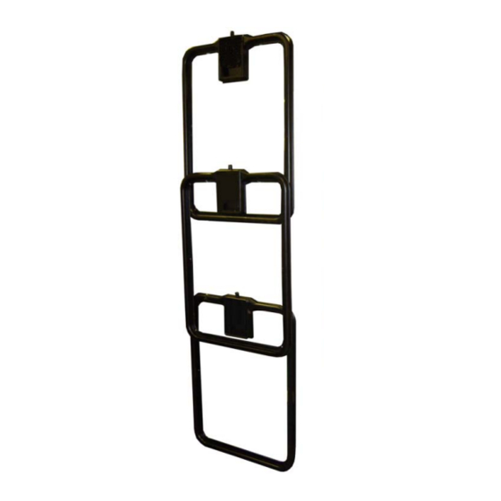
Page 4: Properties And Intended Application Of The Antenna Gate
ID ISC.ANT800/600-DA or can be acquired in an antenna training course offered by FEIG ELECTRONIC GmbH. ® The installation guides can be found on the available from OBID i-scan FEIG ELECTRONIC GmbH. FEIG ELECTRONIC GmbH Seite 4 von 26 N50101-0e-ID-B.doc... -
Page 5: Project Notes
Figure 1 shows the capture area as well as the various label orientations. Figure 1: Capture Area and Label Orientation 4 Antennas 6 Antennas Note: The gate height (GH) is smaller than the mechanical height of the gate. FEIG ELECTRONIC GmbH Seite 5 von 26 N50101-0e-ID-B.doc... - Page 6 Suitable shielding measures need to be taken to prevent this. FEIG ELECTRONIC GmbH Seite 6 von 26 N50101-0e-ID-B.doc...
-
Page 7: Required Components
® on a PC running under Windows. The service software can be found on the OBID i-scan available from FEIG ELECTRONIC GmbH. Also recommended for checking purposes is an SWR meter with SMA jacks. For more detailed information, see ANNEX. -
Page 8: Preparing The Installation Location / Metal-Free Areas
Reader should be located at a distance of at least 50 cm from the antennas. • The Reader housing may not have an electrical connection to any metal parts in the vicinity of the antenna. FEIG ELECTRONIC GmbH Seite 8 von 26 N50101-0e-ID-B.doc... -
Page 9: Installation And Wiring
If a SWR meter is used it has to be placed between the reader an the power-splitter (s. Figure 4). The SWR meter is only used for checking the tuning results and is removed when testing is finished. Figure 4: Mounting of the SWR meter SWR meter LR200 18cm 2.9m 70cm FEIG ELECTRONIC GmbH Seite 9 von 26 N50101-0e-ID-B.doc... -
Page 10: Notes On Installing And Routing The Antenna Cable
7.20 m. This will result in a slight loss of sensitivity. In order to achieve optimum read distances the antenna connection cable should not be shortened or lengthened. Note: Please note the instructions in the installation guide ID ISC.ANT600/800-DA. FEIG ELECTRONIC GmbH Seite 10 von 26 N50101-0e-ID-B.doc... -
Page 11: Tuning The Gate
(s. Figure 7). Figure 7: Mounting direction of the antennas Housing covers facing same direction Housing covers facing different directions Note: All antenna pairs have to be installed in the same direction. FEIG ELECTRONIC GmbH Seite 11 von 26 N50101-0e-ID-B.doc... - Page 12 Jumper setting B Housing covers facing different directions Jumper setting A Table 5: Jumper settings for labels parallel and at right angles to antenna Antenna installation both directions Jumper setting C FEIG ELECTRONIC GmbH Seite 12 von 26 N50101-0e-ID-B.doc...
- Page 13 ® OBID i-scan Application-Note ID ISC.ANT800/600-DA Figure 8: Jumper Settings for Power Splitter Jumper settings A Jumper settings B Jumper settings C FEIG ELECTRONIC GmbH Seite 13 von 26 N50101-0e-ID-B.doc...
-
Page 14: Setting The Multiplexer
Note: For the configuration of the multiplexer see also the installation manual ID ISC.ANT.MUX (M30201-1de-ID-B). 3.2.1. Configuration of the DIP-Switch The DIP-Switch should be configured according to Table 6. Table 6: DIP-Switch Configuration of Multiplexer DIP-Switch S1 FEIG ELECTRONIC GmbH Seite 14 von 26 N50101-0e-ID-B.doc... -
Page 15: Jumper Configuration
Position closed 1Ω Q Resistor open 2Ω Q Resistor Antenna switch open Note: For the configuration of the dynamic antenna tuner see also the installation manual ID ISC.DAT (M40401-xde-ID-B) OBID i-scan® CD. FEIG ELECTRONIC GmbH Seite 15 von 26 N50101-0e-ID-B.doc... -
Page 16: Reader Configuration
Reader the PC ® Install the ISOStart on OBID i-scan service software Start the ISOStart software Carry out a „Detect“..follow the „New-File Assistant“..and read out the current Reader configuration FEIG ELECTRONIC GmbH Seite 16 von 26 N50101-0e-ID-B.doc... - Page 17 (here ISO 15693) FSK Transponder set to „0x02 both antennas“ „Write“ to set parameters System Parameters CFG10: General For tuning, the „ISO-Host Mode“ must be activated „Write“ to set parameters FEIG ELECTRONIC GmbH Seite 17 von 26 N50101-0e-ID-B.doc...
-
Page 18: Tuning The Antennas
After a successful tuning procedure both antennas of gate1are colored green in the tree After a successful tuning of the antennas the software DATuningTool has to be closed. FEIG ELECTRONIC GmbH Seite 18 von 26 N50101-0e-ID-B.doc... -
Page 19: Checking The Standing Wave Ratio Swr (Optional)
The cable between the Reader and SWR meter should be either very short (< 20cm) or 7.20 m (RG58 = λ/2) long. After checking the SWR the SWR meter and the 18cm connection length between the SWR meter and the T fitting on the Reader are removed. FEIG ELECTRONIC GmbH Seite 19 von 26 N50101-0e-ID-B.doc... -
Page 20: Starting Up And Testing The Gate
Send Command to Reader Click on “Test and Measurement” button Select the „Noise Level“ function and start by clicking on the „Start“ button. Nominal noise level values: Average: 400-750mV Difference (Max-Min): < 20mV FEIG ELECTRONIC GmbH Seite 20 von 26 N50101-0e-ID-B.doc... - Page 21 • Are there devices nearby which could affect operation of the gate (larger machines or RF devices) ? To determine which devices may be affecting operation of the gate, momentarily interrupt supply to them one at a time. FEIG ELECTRONIC GmbH Seite 21 von 26 N50101-0e-ID-B.doc...
-
Page 22: Reading Out A Serial Number
Repeat Step 2 to 7 for Output Channel Input1: 2 Output Channel Input2: 7 For a Gate with 6 antennas repeat step 2 to 7 for Output Channel Input1: 3 Output Channel Input2: 6 FEIG ELECTRONIC GmbH Seite 22 von 26 N50101-0e-ID-B.doc... -
Page 23: Testing The Performance
±2.5 cm). Now slowly move the label vertically and horizontal in the gate as shown in Figure 10. The label should always be read. Figure 10: Performance Test with parallel Label Orientation FEIG ELECTRONIC GmbH Seite 23 von 26 N50101-0e-ID-B.doc... -
Page 24: Testing Right Angels Label Orientation
Repeat this test on the back side of the antenna. The capture area must cover the entire capture area. Figure 11: : Performance Test with right angles Label Orientation FEIG ELECTRONIC GmbH Seite 24 von 26 N50101-0e-ID-B.doc... -
Page 25: Setting Buffered Read Mode
CFG11: Buffered Read Mode: TR.DATA Serial Number VALID-TIME 300 x 100 ms „Write“ to set parameters System Parameters CFG10: General Enable Buffered Read Mode Enable Anticollision Select Mode „Write“ to set parameters FEIG ELECTRONIC GmbH Seite 25 von 26 N50101-0e-ID-B.doc... -
Page 26: Annex
Diameter da=28, di=16, I=20, B.Nr.742 701 4 Diameter da=40,6 di=27,4 I=15, B.Nr.742 701 5 Vendor: Würth Elektronik GmbH & Co.KG Riedenstraße 16 74635 Kupferzell Tel.: +49 (0)7944 / 91 93 0 http://www.we-online.de FEIG ELECTRONIC GmbH Seite 26 von 26 N50101-0e-ID-B.doc...