Table of Contents
Advertisement
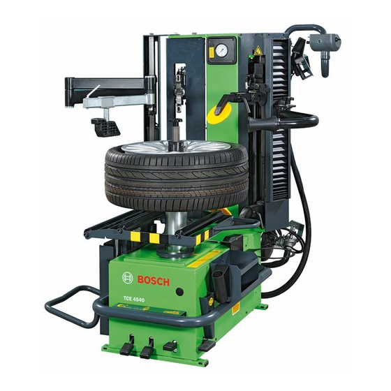
TCE 4540
de Originalbetriebsanleitung
Reifenmontiermaschine
es Manual original
Máquina para montaje de neumáticos
nl Oorspronkelijke gebruiksaanwijzing
Bandenmonteermachine
cs Původní návod k používání
Stroj pro montáž a demontáž pneu-
matik
en Original instructions
Tire changer
it Istruzioni originali
Smontagomme
pt Manual original
Máquina de montagem de pneus
tr Orijinal işletme talimatı
Lastik sökme ve takma makinesi
fr Notice originale
Machine à monter les pneus
sv Bruksanvisning i original
Däckmonteringsmaskin
pl Instrukcją oryginalną
Zmieniacz opon
zh 原始的指南
轮胎装配机
Advertisement
Table of Contents

Related Manuals for Bosch TCE 4540


Summary of Contents for Bosch TCE 4540
- Page 1 TCE 4540 de Originalbetriebsanleitung en Original instructions fr Notice originale Reifenmontiermaschine Tire changer Machine à monter les pneus es Manual original it Istruzioni originali sv Bruksanvisning i original Máquina para montaje de neumáticos Smontagomme Däckmonteringsmaskin nl Oorspronkelijke gebruiksaanwijzing pt Manual original pl Instrukcją...
-
Page 3: Table Of Contents
26 | TCE 4540 | Contents Symbols used Maintenance Documentation Suggested lubricants TCE 4540 Cleaning and servicing Additional adhesive tags 6.2.1 Service intervals 6.2.2 Condensate removal User information 6.2.3 Nebulizer oil refi ll Important notes 6.2.4 Change oil in the oil nebulizer Safety instructions 6.2.5... -
Page 4: Symbols Used
Important – warns of a potentially hazardous situa- tion in which the TCE 4540, the test sample or other object in the vicinity could be damaged. In addition to these warnings, the following symbols are also used: Info –... -
Page 5: User Information
A pneumatic connection is requested. Electromagnetic compatibility (EMC) Delivery specification The TCE 4540 is a class A product as per EN 61 326. Denomination Order code TCE 4540 Wheel lift moving part... -
Page 6: Description Of Unit
Description of unit Description of function Below are reported the main functions of the listed On the TCE 4540 there are rotating and mo- components of the TCE 4540: ving parts that could injure fingers and arms. Pedal box, includes the control pedals of the equip-... - Page 7 30 | TCE 4540 | Product description Pos. Name Function Wheel lifter pedal Wheel placement: + Complete lifting/lowering of the wheel lifter: press the pedal shortly and energetically. + Gradual lowering of the wheel lifter: press the pedal continuously and gently.
-
Page 8: Initial Commissioning
Dispose correctly of packaging material, hand it over to the designated collection points. Installation 1. Loosen the four screws that fix TCE 4540 to the pallet. Warning - tilting danger! The barycentre of the TCE 4540 is not at its centre. -
Page 9: Pneumatic Connection
32 | TCE 4540 | Initial commissioning Pneumatic connection 3. Lift the TCE 4540 with a lift crane and install it in the designed area respecting minimum distances as shown in the picture. 1. Connect the TCE 4540 to the compressed air supply unit. -
Page 10: Check Rotation Direction
Initial commissioning | TCE 4540 | 33 Check rotation direction Hydraulic control unit adjustment Warning - malfunctioning danger! Before starting to use the TCE 4540 it is necessary to TCE 4540 turns in counter-clockwise direc- adjust some valves in the hydraulic control unit. tion. -
Page 11: Use
34 | TCE 4540 | Use Tire demounting Warning - tire or rim damage danger! Read the Wdk publications available in German and Excessive pressure can e. g. result in cracks English! (on the inside/outside) of the tire. The rim (www.wdk.de: mounting/demounting instructions) -
Page 12: Preparations For Demounting
Use | TCE 4540 | 35 Introduce the dragging peg in one of the rim's bolt 5.1.2 Preparations for demounting holes. Avoid valve damage! Use a suitable centring cone and insert it into the tightening pin, together with the tightening ring 1. -
Page 13: Demounting
36 | TCE 4540 | Use 5.1.3 Demounting Warning – damage risk for RFT or UHP tires! FCracks might occur in case of operation Warning – hand injury danger! on cold tire. Tire explosion in case of high Risk of crush injuries during tightening flange speed. - Page 14 Use | TCE 4540 | 37 Warning - damage risk! Only when you are sure that the mounting tool has During extraction with the hydraulic system been positioned correctly and that the tire bead control unit the rim and the bead breaking comes out of the rim easily it is possible to activate rollers can both be damaged.
-
Page 15: Tire Mounting
38 | TCE 4540 | Use Tire mounting 11. To move the lower tire bead close to the mounting tool, place the lower bead breaking roller on the edge of the rim and move it upwards with the left Danger! Damaged rims or tires can cause car lever of the control unit. -
Page 16: Mounting Of Non Critical Rim/Tire Combinations
Use | TCE 4540 | 39 2. Lubricate the side of the tire (RFT/UHP) and the tire 5.2.2 Mounting of non critical rim/tire combinations bead (inside/outside) with the mounting paste (as shown in the picture). In case of non critical wheels for bead fitting only the mounting tool and the the tightening flange are used. -
Page 17: Mounting Of Critical Rim/Tire Combinations
40 | TCE 4540 | Use 3. By means of the hydraulic control unit joystick, lift 3. Release the adjustable roller holding arm from the the tool, rotate it and position it on the upper edge handle with screws and bring it in position. - Page 18 Use | TCE 4540 | 41 6. Place the bead pressing device on the tire and use the side lever of the hydraulic control unit to move it downwards placing it directly close to the adjustable roller holding arm. Mounting is complete when the bead pressing device arrives close to the mounting tool thus releasing it completely from the bead.
-
Page 19: Inflation
To protect the operator from eventual dangers that can occur during tire inflating on the tightening flange the TCE 4540 has been equipped with a valve that limits operational pressure to 3,5 bar and with a fur- ther valve limiting maximum pressure to 3,8 bar! To allow quick tire inflation with the tire inflating devi- ce a special pulsing inflation valve is used. -
Page 20: Mounted Wheel Removal
Use | TCE 4540 | 43 Mounted wheel removal Place no object in the area of the wheel supporting bracket! 1. To release the rim from the locking flange unscrew the tightening pin, remove the tightening ring nut and the centring cone. -
Page 21: Functioning Anomalies
To speed up intervention it is important to tell during the phone call the data reported on the identification plate (tag on the back of the TCE 4540) and the type of malfunction. Any intervention on the electrical, hydraulic or pneumatic system, has to be carried out exclusively by qualified technicians which are properly trained. -
Page 22: Maintenance
TCE 4540 and take off the network plug. To guarantee full efficiency of the TCE 4540 and to ensure functioning without anomalies it is essential to clean the machine regularly and carry out periodical maintenance. -
Page 23: Spare Parts And Parts Subject To Wear
1 695 104 910 4. Follow what shown for first start up (see chap. 4.2). 5. Fix again the TCE 4540 with its four screws on the pallet (see chap. 4.2). In case of sale or transfer of TCE 4540, all the docu- ments included in the consignment volume has to be integrally handed over together with the equipment. -
Page 24: Technical Data
Technical data | TCE 4540 | 47 Technical data Glossary TCE 4540 Rim, structure and names Function Specifications Translation length of the tightening 285 mm flange in longitudinal direction Maximum noise level. 75 dB Force of the hydraulic be- 14000 N (1,4 t)