Table of Contents
Advertisement
Advertisement
Table of Contents

Related Manuals for Honeywell NOTIFIER ID61


Summary of Contents for Honeywell NOTIFIER ID61
- Page 1 ID61/62 operating manual 997-458-000-8, Issue 8 January 2010...
-
Page 2: Table Of Contents
ID61/62 Series Panels - Operating Manual Contents Introduction Associated Documents The ID61/62 Series Panels 1.2.1 Device Type Abbreviations Cleaning Panel Controls and Indicators Controls Indicators Automatic Alarms - What to do Fire 3.1.1 Fire in Delayed Mode Pre-alarm Fault 3.3.1 Power Fail Plant Alarm Fault Output: Fault/Disabled (Optional) Operator Actions at Panel... - Page 3 ID61/62 Series Panels - Operating Manual 4.9.5 Outputs - User Option 4.9.6 Buzzer - User Option 4.9.7 Keyboard - User Option 4.10 DISABLE / ENABLE - User Option 4.10.1 Zones - User Option 4.10.2 Outputs - User Option 4.10.3 Day Mode - User Option 4.10.4 Delays - User Option 4.11 CLOCK - User Option 4.11.1 Time - User Option...
- Page 4 ID61/62 Series Panel - Operating Manual ID61/62 Series Panels (ID61 Panel shown) ZONE FIRE ZONE FIRE 2 3 4 5 6 7 8 9 10 11 12 13 14 15 16 ZONE FAULT/ ZONE FAULT/ 0..9 DISABLE/TEST DISABLE/TEST FIRE MUTE BUZZER MUTE BUZZER DISABLEMENT FAULT...
-
Page 5: Introduction
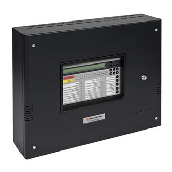
ID61/62 Series Panels - Operating Manual Introduction This manual contains operating instructions for the ID61/ 62 Series Fire Detection Panel. Additional operating instructions for the VIEW™ and SMART 4 sensors are given in Appendix 3. Users of this manual are assumed to be working with a panel that has already been installed and configured appropriately for the area under its supervision. -
Page 6: Device Type Abbreviations
ID61/62 Series Panels - Operating Manual 1.2.1 Device Type Abbreviations Throughout this manual the panel may refer to devices by an abbreviated name. The following table lists the device type abbreviation and its description. Abbreviation Type Description Plant Warning Input Advanced VIEW™... -
Page 7: Panel Controls And Indicators
ID61/62 Series Panel - Operating Manual Panel Controls and Indicators The panel’s controls and indicators are used to operate the overall system and display the panel status. The panel has four function pushbuttons, twelve numeric/cursor keys and thirty-two zonal LED indicators, two ‘FIRE’ indicators and fourteen system status LED indicators. -
Page 8: Indicators
ID61/62 Series Panel - Operating Manual 2.2 Indicators The panel status indicators comprise three groups: a. Zone Status LED indicators. b. Panel/System LED indicators. c. Visible/Audible indicators. Zone Status LED Indicators • ZONE FIRE - these LEDs indicate affected zone(s). •... -
Page 9: Automatic Alarms - What To Do
ID61/62 Series Panel - Operating Manual Automatic Alarms - What to do Before any automatic alarms have been sounded the panel only operates in display mode (quiescent state). Only one alarm condition can be displayed at a time on the LCD. If fire alarms, faults and/or warning conditions (Plant Alarm) are present on the panel at the same time, they are displayed in the following priority order: a. - Page 10 ID61/62 Series Panel - Operating Manual Recommended operator actions: Note: In the recommended operator actions described below EN54-2: 7.6.1, 7.8, 8.7.1, only MUTE BUZZER and END DELAY are selectable 9.1.2 at Access Level 1. The operation of EXTEND DELAY, Ensure EN54 compliance EVACUATE, SILENCE, RESOUND and RESET must for access to controls.
-
Page 11: Fire In Delayed Mode
ID61/62 Series Panel - Operating Manual 3.1.1 Fire in Delayed Mode The DeIayed Mode introduces a delay between an alarm being detected and the sounders and output modules activating. Depending upon the panel configuration, this may be a single delay or a 2-stage delay (an initial brief delay which may be extended by pressing EXTEND DELAY to allow an investigation). -
Page 12: Pre-Alarm
ID61/62 Series Panel - Operating Manual Pre-alarm When one or more input devices signal to the panel a ZONE FIRE reading higher than normal but not yet at the FIRE level, 2 3 4 ZONE FAULT this is a PRE-ALARM condition. DISABLE/TEST FIRE FAULT... - Page 13 ID61/62 Series Panel - Operating Manual Fault Automatic panel actions: ZONE FIRE If a fault occurs, the panel automatically does the 2 3 4 ZONE FAULT following: DISABLE/TEST FIRE a. Operates the internal buzzer (2 sec. on, 1 sec. off). FAULT DISABLEMENT b.
-
Page 14: Power Fail
ID61/62 Series Panel - Operating Manual 2 If a service contact number has been entered during panel commissioning, the LCD alternates between the fault message(s) and the following: FAULT 01 / 03 14:55 For Service Contact ***** ****** Note: Press the MUTE BUZZER pushbutton to silence the panel’s internal buzzer. -
Page 15: Plant Alarm
ID61/62 Series Panel - Operating Manual Plant Alarm A Plant Alarm indication is the default configuration setting for ID61/62 Series fire control panels. In this configuration, the panel operates as follows: A Plant Alarm message is displayed if the panel detects a non-fire input (AUX) configured in zones 17 to 32. -
Page 16: Operator Actions At Panel
ID61/62 Series Panel - Operating Manual Operator Actions at Panel 4.1 Introduction Operator actions at the panel require the correct pushbutton and access code entry. The LCD and the user pushbuttons located on the panel allow the following actions to be carried out: a. -
Page 17: Internal Buzzer
ID61/62 Series Panel - Operating Manual 4.1.2 Internal Buzzer The panel has an internal buzzer which gives a local FIRE warning when any of the following is detected: FAULT DISABLEMENT TEST POWER SUPPLY FAULT a. Fire condition. DELAYS ACTIVE EARTH FAULT FIRE OUTPUT: FAULT / DISABLED SYSTEM FAULT b. -
Page 18: Keyswitch
ID61/62 Series Panel - Operating Manual 4.1.4 Keyswitch The panel is fitted with a keyswitch which provides an alternative to the Level 2 access code. If the keyswitch is in the enabled position, it overrides the requirement for a Level 2 access code. Therefore, if an alarm condition occurs the keyswitch enables the immediate operation of the control keys. -
Page 19: End Delay/Evacuate Pushbutton
ID61/62 Series Panel - Operating Manual 4.4 END DELAY / EVACUATE Pushbutton The END DELAY/EVACUATE pushbutton is used to initiate the Evacuate procedure. If this pushbutton is operated while a delay is active, all delays are cancelled and all sounders designated in the pre-configured Evacuate rule are activated. -
Page 20: Silence/Resound Pushbutton
ID61/62 Series Panel - Operating Manual 4.5 SILENCE / RESOUND Pushbutton The term ‘silence’ as used throughout this manual, describes a temporary state the panel enters whenever the SILENCE / RESOUND pushbutton is pressed to stop the sounders operating. While the panel is in this state, a new fire alarm, operating the SILENCE / RESOUND pushbutton again... -
Page 21: Reset Pushbutton
ID61/62 Series Panel - Operating Manual 4.6 RESET Pushbutton The RESET pushbutton is used to clear all non-quiescent conditions and return the panel to a normal quiescent condition. Provided that the control keys have been enabled for Level 1 operation, the following occurs: a. -
Page 22: Numeric Keys
ID61/62 Series Panel - Operating Manual 4.7 Numeric Keys When using any numeric key, each operation is confirmed by a sharp audible bleep. At Access Level 1, the numeric buttons have NO function until an alarm condition occurs. The alarm condition enables the ‘... -
Page 23: Level 2 Option Menus
ID61/62 Series Panel - Operating Manual 4.8 Level 2 Option Menus The following Level 2 Option Menus are available after a correct Level 2 access code has been input or the keyswitch has been operated (except the Print menu, which is only available if a printer is fitted). The menu map at left shows an overview of the Level 2 menus. -
Page 24: Test - User Option
ID61/62 Series Panel - Operating Manual 4.9 TEST - User Option The following tests are available at Access Level 2 from the Test - User Option menu: a. LEDs b. LCD c. Zones d. Auto High Test e. Outputs f. Buzzer g. -
Page 25: Leds - User Option
ID61/62 Series Panel - Operating Manual 4.9.1 LEDs - User Option This option, selected from the Test menu, illuminates each LED in turn. To test the panel LEDs, enter access Level 2 and follow the procedure below: 1 Using the numeric keypad, press ‘ ’... -
Page 26: Zones - User Option
ID61/62 Series Panel - Operating Manual 4.9.3 Zones - User Option The Test Zones option, selected from the Test Menu, allows the user to perform a walk test on one zone at a time. During the walk test the TEST and relevant FAULT/ DISABLE/TEST LEDs are illuminated, indicating that the system and zone is in TEST mode. - Page 27 ID61/62 Series Panel - Operating Manual Use the ‘ ’ buttons to select the zone, then press the ‘ ’ button to confirm the zone number. [STOP WALK TEST] Select Zone: 01 Press to Confirm <:Cancel ii Press the ‘ ’...
-
Page 28: Auto High Test - User Option
ID61/62 Series Panel - Operating Manual After a few seconds, the panel will automatically return to Test Mode and the device LED will be turned off. The panel is then ready to test the next device. Note: Up to one minute must be allowed for smoke sensors to clear. -
Page 29: Outputs - User Option
ID61/62 Series Panel - Operating Manual 4.9.5 Outputs - User Option The Test Outputs option, accessed from the Test Menu, tests the panel’s internal sounder and relay circuits and the Signalling Line Circuit (SLC) loop outputs. To perform this test: Test Internal Outputs 1 From the Test Menu, press the ‘... - Page 30 ID61/62 Series Panel - Operating Manual Test Loop Booster Outputs A number of tests are available to satisfactorily test the To perform a Loop Booster operation of the Loop Booster Modules (LBMs) during output test an access level 3 alarm conditions. The tests are designed so that the power delivered to the loop by the panel can be switched off from passcode is required.
-
Page 31: Buzzer - User Option
ID61/62 Series Panel - Operating Manual 4.9.6 Buzzer - User Option The Buzzer User Option, selected from the Test Menu, tests the internal buzzer. Proceed as follows: 1 Using the numeric keypad, press ’ ’ to display the TEST menu. [U0] 1 : Test 2 : Disable/Enable 3 : Clock... -
Page 32: Disable / Enable - User Option
ID61/62 Series Panel - Operating Manual 4.10 DISABLE / ENABLE - User Option This option allows the user to disable or enable (depending on their current state) the following parts of the system: a. Zone (Device or Full Zone) b. Outputs c. -
Page 33: Zones - User Option
ID61/62 Series Panel - Operating Manual 4.10.1 Zones - User Option This option allows the user to disable/enable a full zone or part of a zone (selected devices). To perform this operation: 1 Using the numeric keypad, press the ‘ ’... - Page 34 ID61/62 Series Panel - Operating Manual b. A Partial Zone - Press the ‘ ’ button on the numeric keypad to select the Device in Zone option: [Disable/Enable] Zone 0 1 Part disabled 1:Full Zone 2:Device in Zone : More 5 To select individual devices use the ‘...
-
Page 35: Outputs - User Option
ID61/62 Series Panel - Operating Manual 4.10.2 Outputs - User Option The Outputs option allows the user to disable or enable all sounders, the Extinguishant System (if fitted), the Fault Relay and all other Relay and Control outputs. To Disable/Enable these outputs, proceed as follows: [U0 Disable/Enable] 1:Zone 2:Outputs... -
Page 36: Day Mode - User Option
ID61/62 Series Panel - Operating Manual [U0 Disable/Enable] 1:Zone 2:Outputs 3:Day Mode 4:Delays The FIRE CONTROL O/P: FAULT/DISABLED, FIRE OUTPUT: FAULT/DISABLED and the SOUNDERS DISABLED LEDs extinguish when the corresponding outputs have been enabled. The DISABLEMENT LED will only extinguish when ALL disablements have been enabled. -
Page 37: Delays - User Option
ID61/62 Series Panel - Operating Manual 4.10.4 Delays - User Option The Disable / Enable Delays option allows the user to cancel or initiate the Delays function of the panel, which is configured during commissioning (refer to 997-457- 000-X ID61/62 Series Panel Installation,... -
Page 38: Clock - User Option
ID61/62 Series Panel - Operating Manual 4.11 Clock - User Option The CLOCK User Option allows the user to enter or edit the following: a. Time b. Date To edit the CLOCK - User Option: 1 At the ‘Status: NORMAL’ message, press the ‘ ’... -
Page 39: Time - User Option
ID61/62 Series Panel - Operating Manual 4.11.1 Time - User Option The Time User Option allows the user to enter or edit the current time displayed on the LCD. To edit the time, proceed as follows: 1 Press the ‘ ’... -
Page 40: Date - User Option
ID61/62 Series Panel - Operating Manual 4.11.2 Date - User Option The Date User Option allows the user to enter or edit the current date displayed on the LCD. To enter or edit the date, proceed as follows: 1 Using the numeric keypad, press the ‘ ’... -
Page 41: View Mode - User Option
ID61/62 Series Panel - Operating Manual 4.12 View Mode - User Option The VIEW MODE User Option allows the user to view the following system parameters: a. Log b. Devices on the loop c. Faults d. Input Events e. Disablements on the loop f. -
Page 42: Log - User Option
ID61/62 Series Panel - Operating Manual 4.12.1 Log - User Option The Log User Option allows the user to view all logged events, one at a time. To display the Log, from the VIEW Mode menu: 1 On the numeric keypad, press the ‘ ’... -
Page 43: Devices - User Option
ID61/62 Series Panel - Operating Manual 4.12.2 Devices - User Option The Devices User Option allows the user to observe all loop devices in turn. Device data is displayed on the bottom line of the display and the format depends on the configured protocol (CLIP or OPAL) of the selected device. -
Page 44: Faults - User Option
ID61/62 Series Panel - Operating Manual AWACS Devices The ID61/62 panels allow the configuration of all sensor types, except HEAT sensors, to use the AWACS multi- sensing algorithm. For these devices an additional screen is available which displays the current percentage values for alarm and pre-alarm. -
Page 45: Input Events - User Option
ID61/62 Series Panel - Operating Manual 4.12.4 Input Events - User Option The Input Events menu option allows the user to view active input events/plant alarms while the normal active input events/plant alarms display has been overridden by a higher priority display (alarms). To view Plant Alarms, from the View Mode menu: 1 Using the numeric keypad, press the ‘... -
Page 46: Disabled - User Option
ID61/62 Series Panel - Operating Manual 4.12.5 Disabled - User Option The Disablement User Option allows the user to view all current loop-based input disablements recorded on the system. To view each disablement in turn, from the VIEW Mode menu: 1 Using the numeric keypad, press the ‘... -
Page 47: Voltages - User Option
ID61/62 Series Panel - Operating Manual 4.12.7 Voltages - User Option With sounder circuits configured as transmission The Voltages User Option allows the user to view the device (TxD) the Voltages User option is used Voltages (mV) of various parts of the system. For sounder to set the transmission circuit reference circuits configured as a transmission device (TxD) a impedance. -
Page 48: Version - User Option
ID61/62 Series Panel - Operating Manual 4.12.8 Version - User Option The Version User Option allows the user to view the System and Loop part numbers and revision levels used in the system. To view the Versions, from the View Mode menu: 1 Using the numeric keypad, press the ‘... -
Page 49: Print Log
ID61/62 Series Panel - Operating Manual 4.14.1 Print Log This option prints events from the log. Proceed as follows: 1 At the Print menu, press ‘ ’ on the numeric keypad to select the Log option. [U0 PRINT] 1 : Log 2 : Disablements 3 : On-Demand 4 : Maintenance... -
Page 50: Print On-Demand
ID61/62 Series Panel - Operating Manual 4.14.3 Print On-Demand This option is only available if the panel was configured for ‘On-Demand’ printing during commissioning. Note: If On-Demand is not configured, events are printed as they occur. If On-Demand is configured, events are only printed via the menu as described below. -
Page 51: Print Maintenance Log
ID61/62 Series Panel - Operating Manual 4.14.5 Printing Maintenance Log The Print Maintenance option is available for SMART multi-criteria sensors. [U0 PRINT] 1 : Log 2 : Disablements 3 : On-Demand 4 : Maintenance 1 At the Print menu, press‘ ’... -
Page 52: Appendix 1 - Log Book A1-1
ID51/52 Series Panel - Operating Manual Appendix 1 - Log Book In accordance with EN54 part 14, it is the user’s responsibility to maintain a log book and to record all events resulting from or affecting the system. The log book should be kept in a place accessible to authorised persons (preferably near the control panel). - Page 53 ID51/52 Series Panel - Operating Manual Event Data Date Time Event Action Required Date Completed Initials 997-458-000-8, Issue 8 A1 - 2 January 2010...
- Page 54 ID51/52 Series Panel - Operating Manual Event Data Date Time Event Action Required Date Completed Initials A1 - 3 997-458-000-8, Issue 8 January 2010...
- Page 55 ID51/52 Series Panel - Operating Manual Event Data Date Time Event Action Required Date Completed Initials 997-458-000-8, Issue 8 A1 - 4 January 2010...
-
Page 56: Appendix 2 - Maintenance A2-1
ID51/52 Series Panel - Operating Manual Appendix 2 - Maintenance Create a log book (see Appendix 1) in accordance with the recommendations of EN54 Part 14. This log book should be used and maintained for recording events as described below. A2.1 Routine Testing In order to ensure that the system is fully operational, and to comply with the requirements of EN54 Part 14... - Page 57 ID61/62 Series Panel - Operating Manual Appendix 3 VIEW™ & SMART 4 Sensors The ID61/62 panels support Very Intelligent Early Warning (VIEW ) sensors and SMART 4 multi-criteria sensors. This appendix describes differences to the user operations for these devices. Each VIEW sensor has to be calibrated on first operation with the panel.
- Page 58 Charles Avenue T: +44 (0) 1444 230 300 Burgess Hill F: +44 (0) 1444 230 888 W. Sussex E: sales@notifierfiresystems.co.uk RH15 9UF www.notifierfiresystems.co.uk local distributor Quality Systems Certificate No. 154 Assessed to ISO9001 Every care has been taken in the preparation of this document but no liability can be accepted for the use of the information therein. Design features may be changed or amended without prior notice.