
Related Manuals for Honeywell Gamewell FCI S3 Series


Summary of Contents for Honeywell Gamewell FCI S3 Series
- Page 1 S3 Series System (Small Addressable Fire Alarm Control Panel) Underwriters Laboratories Listing Document Document:LS10005-051GF-E 3/09/2016 Rev: P/N LS10005-051GF-E:D3 ECN 15-0375...
- Page 2 Fire Alarm & Emergency Communication System Limitations While a life safety system may lower insurance rates, it is not a substitute for life and property insurance! An automatic fire alarm system—typically made up of smoke Heat detectors do not sense particles of combustion and alarm detectors, heat detectors, manual pull stations, audible warning only when heat on their sensors increases at a predetermined devices, and a fire alarm control panel (FACP) with remote notifi-...
- Page 3 Acclimate®, FocalPoint®, Gamewell-FCI®, FAAST Fire Alarm Aspiration Sensing Technology®, Intelligent FAAST® SmartScan®, SWIFT®, Velociti®, and E3 Series® are registered trademarks of Honeywell International Inc.eVance™ is a trademark; and Silent Knight® and SWIFT® are registered trademarks of Honeywell International Inc. Microsoft® and Windows® are registered trademarks of the Microsoft Corporation Chrome™...
- Page 4 •Brief description of content you think should be improved or corrected •Your suggestion for how to correct/improve documentation Send email messages to: FireSystems.TechPubs@honeywell.com Please note this email address is for documentation feedback only. If you have any technical issues, please contact Technical Services.
-
Page 5: Table Of Contents
Table of Contents Section 1: Introduction......................8 1.1: S3 Series Small Addressable Fire Alarm Control Panel ................8 1.1.1: S3 Series Reference Documentation ....................8 1.2: Standards................................9 1.3: Product Models Nomenclature ........................9 Section 2: Installation Wiring....................10 2.1: Main Supply Circuit ............................10 2.1.1: FLPS-7 Main Supply Installation Wiring Diagram................10 2.1.2: FLPS-7 Installation Wiring Terminals ....................10 2.1.3: FLPS-7 Main Supply Circuit Specifications ..................10... - Page 6 Table of Contents 2.10.4: RPT-E3-UTP Installation Wiring Terminals...................27 2.10.5: RPT-E3-UTP Programming Address Switch Settings ..............28 2.10.6: FML-E3 Installation Wiring Diagram .....................29 2.10.7: FML-E3 Installation Wiring Terminals...................29 2.10.8: FSL-E3 Installation Wiring Diagram ....................30 2.10.9: FSL-E3 Installation Wiring Terminals ....................30 2.10.10: DACT-E3 Communication Circuit....................30 2.11: Power Output Circuits..........................31 2.11.1: Power Output Specifications ......................31 2.12: Releasing Device Circuit ...........................32...
- Page 7 Table of Contents 8.3: S3 Series Module System Configurations ....................56 Section 9: System Power/Size ....................57 Index............................58 S3 Series UL Listing Document — P/N LS10005-051GF-E:D3 3/09/2016...
-
Page 8: Section 1: Introduction
Section 1: Introduction 1.1 S3 Series Small Addressable Fire Alarm Control Panel This Underwriter’s Laboratory Listing Document describes the design and operation of the principal components of the S3 Series (Small Addressable Fire Alarm Control Panel). The S3 Series is a Small Analog- Addressable Fire Alarm Control Panel (FACP) that may be used in standalone or networked configurations. -
Page 9: Standards
Standards Introduction 1.2 Standards The S3 Series System complies with the following Standards: Underwriters Laboratories Standards The S3 Series System is suitable for the following signaling services that comply with the Underwriters Laboratories Standards: • UL Standard 864 9th Edition: –... -
Page 10: Section 2: Installation Wiring
Section 2: Installation Wiring This product is intended to be installed in accordance with local, regional and National standards. The S3 Series System (Small Addressable Fire Alarm Control Panel) comprises the following modules. Required Modules Optional Modules • SLP-E3 (Smart Loop Panel-Main Board) •... -
Page 11: Slp-E3 Main Circuit Installation Wiring Diagram
SLP-E3 Main Circuit Installation Wiring Diagram Installation Wiring 2.2 SLP-E3 Main Circuit Installation Wiring Diagram The S3 Series System uses the SLP-E3 main board as the main circuit board. Figure 2.2.1 shows the SLP-E3 main circuit board sub-assembly. NAC CIRCUITS SLC-PM/SLC95-PM #1 B- B+ CIRCUITS... - Page 12 Installation Wiring SLP-E3 Main Circuit Installation Wiring Diagram Designation Description Comments TB4-5 SUPV NO Supervisory relay contact normally OPEN N/O TB4-6 SUPV C Supervisory relay contact common TB4-7 TRBL NC Trouble relay contact normally CLOSED N/C TB4-8 TRBL NO Trouble relay contact normally OPEN N/C TB4-9 TRBL C Trouble relay contact common...
-
Page 13: 2: Slp-E3 Rechargeable Battery Circuit Installation Wiring Diagram
SLP-E3 Main Circuit Installation Wiring Diagram Installation Wiring 2.2.2 SLP-E3 Rechargeable Battery Circuit Installation Wiring Diagram Figure 2.2.2.1 shows the SLP-E3 rechargeable battery installation wiring diagram. WARNING! SLC-PM/SLC95-PM #1 B- B+ INSTALLTHE (SEE WARNING). SLC-PM/ SLC95-PM COMPONENT SIDE UP! SLC-PM/SLC95-PM #2 (SEE WARNING). -
Page 14: 5: Slp-E3 Standby Battery Calculation Chart
Installation Wiring SLP-E3 Main Circuit Installation Wiring Diagram NOTES NOTE 1: Four hour standby permitted for installations with automatic backup generators. 24, 60 hours as required by code. Use Table 2.2.5.1 to obtain the correct sized battery capacity required. NOTE 2: 5, 15, 30 or 60 minute Alarm duration as required by code. Use Table 2.2.5.1 to obtain the correct sized battery capacity required. -
Page 15: Initiating Device Circuit
Initiating Device Circuit Installation Wiring NOTES (Continued) NOTE 3: Normal operating current.During a power failure, current drops to 0.045 amp since backlight is extinguished. NOTE 4: Add .003 amp for any LED to be lit for any condition when powered internally. NOTE 5: Add .003 amp for any LED to be lit for any condition when powered internally. -
Page 16: 2: Slp-E3 Main Board Outputs
Installation Wiring Supplementary Circuits Table 2.4.1.1 lists the Notification Appliance Circuit specifications. Requirements NACs Specifications Circuit Supervision: Supervised Power-Limited: Class 2 Power-Limited Type of signaling devices and connection, if Refer to Figure 2.4.1.1. polarized, indicate proper wiring with plus or minus (+-) symbols, or equivalent for proper field connection. -
Page 17: Signaling Line Circuit (Slc) (Slc-Pm/Slc95-Pm)
Signaling Line Circuit (SLC) (SLC-PM/SLC95-PM) Installation Wiring 2.6 Signaling Line Circuit (SLC) (SLC-PM/SLC95-PM) The SLP panel provides the option of either of the following Loop Cards: • SLC-PM (Signaling Line Circuit-Personality Module) The SLC-PM is used with the System Sensor devices. •... -
Page 18: 2: Slc-Pm Installation Wiring Diagram- System Sensor
Installation Wiring Signaling Line Circuit (SLC) (SLC-PM/SLC95-PM) 2.6.2 SLC-PM Installation Wiring Diagram- System Sensor Figure 2.6.2.1 illustrates the SLC-PM circuit board diagram. For system assembly and installation wiring ter- minal designations, refer to the SLC-PM/SLC95-PM Installation Instructions, P/N: LS10044-000GF-E. You can download this document from the Gamewell-FCI Website (www.gamewell-fci.com). -
Page 19: 5: Slc95-Pm Installation Wiring Diagram - Apollo
Signaling Line Circuit (SLC) (SLC-PM/SLC95-PM) Installation Wiring 2.6.5 SLC95-PM Installation Wiring Diagram - Apollo Figure 2.6.5.1 shows the SLC95-PM circuit board diagram. For system assembly and installation wiring ter- minal designations, refer to the SLC-PM/SLC95-PM Installation Instructions, P/N: LS10044-000GF-E. You can download this document from the Gamewell-FCI Website (www.gamewell-fci.com) SLC95-PM Figure 2.6.5.1 SLC95-PM Circuit Board... -
Page 20: Remote Annunciator/Keypad Circuits
Installation Wiring Remote Annunciator/Keypad Circuits 2.7 Remote Annunciator/Keypad Circuits In the S3 Series System, the SLP-E3 supports the following remote annunciators: • ANU-48 • ASM-16 • LCD-7100 • RAN-7100 • LCD-SLP • LCD-E3 2.7.1 ANU-48 Remote Annunciator In the S3 Series System, you can use up to sixteen ANU-48 remote annunciators to remotely connect to the SLP-E3 panel. -
Page 21: 7: Remote Annunciator Installation Wiring Diagram
Remote Annunciator/Keypad Circuits Installation Wiring 2.7.7 Remote Annunciator Installation Wiring Diagram In the S3 Series System, the Liquid Crystal Display-Smart Loop Panel (LCD-SLP) is the Local Annuncia- tor/Keypad Circuit for the SLP. Figure 2.7.7.1 illustrates the remote annunciators on the SLP main board panel. -
Page 22: 10: Lcd-Slp Installation Wiring Diagram
Installation Wiring Remote Annunciator/Keypad Circuits 2.7.10 LCD-SLP Installation Wiring Diagram Figure 2.7.10.1 illustrates the LCD-SLP circuit board diagram. For system assembly and installation wiring terminal designations, refer to the LCD-SLP Installation Instructions, P/N: LS10045-000GF-E. You can download this document from the Gamewell-FCI Website (www.gamewell-fci.com). B- B+ SLC-PM/SLC95-PM #1 SLC-PM/SLC95-PM #2... -
Page 23: 12: Lcd-Slp Keypad Circuit Specifications
Remote Annunciator/Keypad Circuits Installation Wiring NOTE 3: Connects to the SLP-E3 J7, when the LCD-SLP is installed in the same cabinet, or similar. NOTE 4: D IS P L A Y # 1 D IS P L A Y # 2 D IS P L A Y # 3 D IS P L A Y # 4 O F F... -
Page 24: 13: Cabinet Enclosure For Lcd-Slp
Installation Wiring Reverse Polarity Communication Circuit 2.7.13 Cabinet Enclosure for LCD-SLP Table 2.7.13.1 lists the cabinet enclosures you can use to install the LCD-SLP. Cabinet Part Numbers Dimensions SLP-BB cabinet (also called the B-Slim cabinet) SLP-BB 14 1/2” W x 20 1/8” H x 4 1/2” D S3 Series, B-Size Cabinet S3BB-BB/RB 19.38”... -
Page 25: 1: W1 Jumper Block (Polarity Reversal Configuration)
Municipal Box Connection Installation Wiring 2.8.1 W1 Jumper Block (Polarity Reversal Configuration) Figure 2.8.1.1 illustrates the W1 jumper block positions for the polarity reversal configuration. Figure 2.8.1.1 W1 Jumper Block Positions for Polarity Reversal Table 2.8.1.1 lists the Reverse Polarity communication line circuits. Designation Description Comments... -
Page 26: 1: W1 Jumper Block (Master Box/Releasing Solenoid Configuration)
Installation Wiring Communication Circuits 2.9.1 W1 Jumper Block (Master Box/Releasing Solenoid Configuration) Figure 2.9.1.1 illustrates the W1 jumper block positions for the Master Box/Releasing Solenoid configuration. Figure 2.9.1.1 W1 Jumper Block Positions for Master Box/Releasing Solenoid 2.10 Communication Circuits 2.10.1 S3 Series System Communication Circuits The RPT-E3-UTP is the network communication circuit for the S3 Series System. -
Page 27: 4: Rpt-E3-Utp Installation Wiring Terminals
Communication Circuits Installation Wiring 2.10.4 RPT-E3-UTP Installation Wiring Terminals Table 2.10.4.1 lists the RPT-E3-UTP terminal wiring designations. Designation Description Comments TB1-1 ARCNET PORT 1A Broadband Network (See Note 1) For Ground Fault Supervision, PORT 1A = IN from the previous panel or node.(See Note 5). TB1-2 ARCNET PORT 1B Broadband Network (See Note 1) For Ground Fault Supervision,... -
Page 28: 5: Rpt-E3-Utp Programming Address Switch Settings
Installation Wiring Communication Circuits Designation Description Comments NOTE 5: FIBER MODULE #1 RESTRICTION: If you use TB1-1 and TB1-2 for Port 1, do not install Fiber Module #1 in connector J5. NOTE 6: FIBER MODULE #2 RESTRICTION: If you use TB1-3 and TB1-4 for Port 2, do not install Fiber Module #2 in connector J6. Table 2.10.4.1 Repeater-E3-UTP Installation Wiring Terminals (Continued) 2.10.5 RPT-E3-UTP Programming Address Switch Settings To set the address, use switch SW1. -
Page 29: 6: Fml-E3 Installation Wiring Diagram
Communication Circuits Installation Wiring 2.10.6 FML-E3 Installation Wiring Diagram The Fiber-Optic Multi-Mode (FML-E3) is an optional module that provides fiber connectivity to the network. One FML-E3 is used per a network channel to transmit/receive. Figure 2.10.6.1 illustrates the FML-E3 circuit board diagram. -
Page 30: 8: Fsl-E3 Installation Wiring Diagram
Installation Wiring Communication Circuits 2.10.8 FSL-E3 Installation Wiring Diagram The Fiber-Optic Single-Mode (FSL-E3) is an optional module that provides fiber connectivity to the network. One FSL-E3 is used per a network channel to transmit/receive. Figure 2.10.8.1 lists the FSL-E3 (Fiber-Optic Single-Mode) circuit board diagram. -
Page 31: Power Output Circuits
Power Output Circuits Installation Wiring 2.11 Power Output Circuits Figure 2.11.1 illustrates the location of the power output circuits for the SLP main board panel. TB 1 SLC-PM /SLC95-PM #1 B- B+ SLC-PM /SLC95-PM #2 J6 J1 TB 4 TB 3 TB 2 TB 5 PO W ER... -
Page 32: Releasing Device Circuit
Installation Wiring Releasing Device Circuit 2.12 Releasing Device Circuit Figure 2.12.1 illustrates the Releasing Device circuit on the SLP main board panel. SLC-PM/SLC95-PM #1 B- B+ SLC-PM/SLC95-PM #2 SLP-E3 BAR CODE RELEASING DEVICE CIRCUIT LABEL PRODUCT SERIAL NUMBER (NON POWER-LIMITED) PRODUCT DATE CODE LABEL... -
Page 33: Relay Circuit, Open Collector And Other Similar Outputs
Relay Circuit, Open Collector and Other Similar Outputs Installation Wiring 2.13 Relay Circuit, Open Collector and Other Similar Outputs Figure 2.13.1 illustrates the Relay, Open Collector and other similar outputs on the SLP main board panel. SLC-PM/SLC95-PM #1 B- B+ RELAY, OPEN COLLECTOR, AND OTHER... -
Page 34: S3 Series System, Slp-Bb Cabinet Assembly
Installation Wiring S3 Series System, SLP-BB Cabinet Assembly 2.14 S3 Series System, SLP-BB Cabinet Assembly The SLP-BB (Smart Loop Panel-Backbox) (Part Number: SLP-BB) assembly typically houses the following units: • Backbox – SLP Main Board – FLSP-7 Power Supply – RPT-E3-UTP (Optional) –... -
Page 35: Separation Of Circuits
Separation of Circuits Installation Wiring 2.15 Separation of Circuits 2.15.1 S3 Series, SLP-BB Cabinet, Class 2 Power-Limited/Non Power-Limited Wiring Requirements UL Standard 864, (Control Units for Fire Protective Signaling Systems), requires that a minimum of 1/4 inch separation be maintained between Class 2 power-limited circuits and non power-limited circuits. The control unit is designed so that the required separation between these circuits (Class 2 power-limited vs. - Page 36 Installation Wiring Separation of Circuits Figure 2.15.1.2 illustrates the S3 Series System unit, Class 2 power-limited and non-power-limited wiring extending from the SLP-E3 and FLPS-7 modules. SLC CIRCUITS FROM SLC-PM (SYSTEM SENSOR) OR SLC95-PM (APOLLO) TB1 (CLASS 2 POWER-LIMITED, SUPERVISED) -CONNECT TO PRINTER AUXILIARY RS485 PORT.
-
Page 37: S3 Series System, B-Size Cabinet Assembly
S3 Series System, B-Size Cabinet Assembly Installation Wiring 2.16 S3 Series System, B-Size Cabinet Assembly The S3 Series, B-Size cabinet assembly (Part Number: E3BB-BB/RB) typically houses the following units: • Backbox – SLP Main Board – FLPS-7 Power Supply – RPT-E3-UTP (Optional) –... -
Page 38: Separation Of Circuits
Installation Wiring Separation of Circuits 2.17 Separation of Circuits 2.17.1 S3 Series, B-Size Cabinet, Class 2 Power-Limited/Non Power-Limited Wiring Requirements UL Standard 864, (Control Units for Fire Protective Signaling Systems), requires that a minimum of 1/4 inch separation be maintained between Class 2 power-limited circuits and non power-limited circuits. The control unit is designed so the required separation between these circuits (Class 2 power-limited vs. - Page 39 Separation of Circuits Installation Wiring Figure 2.17.1.2 illustrates the S3 Series System, B-Size cabinet, Class 2 power-limited and non-power-limited wiring extending from the optional top level circuit board configuration. SLC CIRCUITS FROM SLC-PM (SYSTEM SENSOR) OR SLC95-PM (APOLLO) TB1 (CLASS 2 POWER-LIMITED, SUPERVISED) NETWORK USING FIBER...
-
Page 40: E3 Series, Cabinet A2 Assembly
Installation Wiring E3 Series, Cabinet A2 Assembly 2.18 E3 Series, Cabinet A2 Assembly The E3 Series, Cabinet A2 assembly (Part Number: E3BB-BA2/RA2) typically houses the following units: • Backbox • Inner Door – LCD-SLP Display Panel – LCD-E3 (Optional) • Outer Door –... -
Page 41: E3Bb-Flush-Lcd Cabinet A2 Assembly
E3BB-FLUSH-LCD Cabinet A2 Assembly Installation Wiring 2.18.1.2 E3 Series Cabinet A2, Sub-Assembly to the Inner Door Installation Figure 2.18.1.2.1 illustrates the LCD-SLP remote annunciator connected to the E3 Series Cabinet A2 inner door installation. To connect the LCD-SLP to the inner door, insert and secure four, #6-32 nuts in the four-hole mounting pattern as shown in Location 1 in the figure below. - Page 42 Installation Wiring E3BB-FLUSH-LCD Cabinet A2 Assembly 2.19.1.1 E3BB-FLUSH-LCD Cabinet A2 Front Cover to Backbox Installation Figure 2.19.1.1.1 illustrates the E3BB-FLUSH-LCD front cover to the backbox installation. Mount the keyswitch to the E3BB-FLUSH-LCD Flush Mount Front Cover and secure with one, nut (3/4- 24 THD Hex) as shown in Location 1 in the figure below.
-
Page 43: S3 Series System Configuration
S3 Series System Configuration Installation Wiring 2.20 S3 Series System Configuration Figure 2.20.1 illustrates an overview of the S3 Series System configuration. SLP-E3 Overview Diagram NACs Dry Contact SLC-PM or Relays SLC95-PM connects to Remote Displays, SLC Devices ASM-16s (See Note 1) SLP-E3 LCD-SLP connects to... -
Page 44: Section 3: Operation
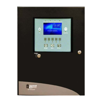
Section 3: Operation 3.1 LCD-SLP Operation 3.1.1 LCD-SLP Panel Display Operation The LCD-SLP is a 4.3” diagonal, 480 x 272 pixels touchscreen display of system events including indicating LEDs and control switches. It may be remotely located via a local RS-485 serial interface. The SLP-E3 will support up to fifteen, LCD-SLP displays. -
Page 45: 4: Lcd-Slp Switches
S3 Series System Operation Operation 3.1.4 LCD-SLP Switches Figure 3.1.4.1 illustrates the LCD-SLP switches. Table 3.1.4.1 lists the LCD-SLP switches and a description. FIRE ALARM HAZARD SUPERVISORY TROUBLE AC POWER SILENCED MENU DRILL RESET Figure 3.1.4.1 LCD-SLP Switches Designation Description Menu Toggles the Menu ON and OFF. -
Page 46: Section 4: Functionality
Section 4: Functionality 4.1 SLP Main Board Features The SLP-E3 Main Board features shall include the following: • An advanced micro-controller system. • Sufficient volatile memory for either standalone or networked functionality. • Sufficient non-volatile memory for the requisite configuration data and a minimum of 4000 event log entries. - Page 47 SLP Main Board Features Functionality UL Standard Functions S3 Functionality Alarm Verification Yes, the S3 has Alarm Verification. Refer to the UL Standard 864 9th Edition, Sections 55.2 to 55.28 . Figure 4.1.1.1 illustrates the Alarm Verification Timing. INITIAL CONFIRMED ALARM OR NEW ALARM ADVANCED DEVICE DETECTION...
-
Page 48: 1: Default Display Priority
Functionality SLP Main Board Features UL Standard Functions S3 Functionality DARC Check In: Primary Power Source Failure: The primary power source failure of constantly attended supervising station equipment, for methods to determine when the fault condition is obvious to the operator on duty is covered in the instructions. S3 Functionality: Yes, the Primary Power Source Failure for the SLC System signals with an AC (green) LED that is lit only when the system is running... -
Page 49: 2: Expected Operations Conditions
SLP Main Board Features Functionality 4.1.2 Expected Operations Conditions Table 4.1.2.1 lists the conditions, response process of the condition and the expected operation. Condition Expected Operation Fire Alarm The following lists the expected operation for a Fire Alarm: Alarm condition processed by Node 1 and the response process begins as follows: •... -
Page 50: Section 5: Programming Options
Programming Options uIP Code License Section 5: Programming Options THE FOLLOWING ARE GAMEWELL-FCI PROGRAMMING SETTINGS THAT WILL BE MODIFIED FOR CAMWORKS PROGRAMMING. Notice to Users, Installers, Authorities Having Jurisdiction and Other Involved Parties: This product uses the CAMWorks™ Programming. You cannot program this product from the Display Panel. To program this product, you must contact your Gamewell-FCI Customer Support Representative to schedule a Factory Certified Training Class. -
Page 51: Programming Menu Selections
Programming Menu Selections Programming Options 5.2 Programming Menu Selections System programming is performed via a portable computer and the Gamewell-FCI CAMWorks™ Configuration. The following menu options are available via the optional LCD-SLP display/keypad module. 5.2.1 MAIN LCD-SLP Menu Selections Table 5.2.1.1 lists the Main LCD-SLP Menu selection and description. NOTE: The SLP Firmware Version also supports the LCD-E3 sub-assembly. -
Page 52: 5: Misc Menu Selection
Programming Options Programming Menu Selections 5.2.5 MISC Menu Selection This selection opens a “MISC OPTS” Menu that allows the user to change the RS-232 port baud rate. The user can override the baud rate settings by using a DIP switch on the SLP board. The baud rate options are provided to allow the connection to a variety of printers. -
Page 53: Section 6: Testing/Maintenance
Section 6: Testing/Maintenance When finished with the original installation and all modifications, conduct a complete operational test on the entire installation to verify compliance with applicable NFPA standards. Testing should be conducted by a factory-trained fire alarm technician in the presence of a representative of the Authority Having Jurisdiction and the owner’s representative. -
Page 54: Section 7: Compatibilities
Compatibilities Section 7: Compatibilities To obtain the devices that are compatible with the SLP Main Board, refer to the Compatibility Addendum for Gamewell-FCI Manuals, P/N: 9000-0427. You can download the Compatibility Addendum for Gamewell-FCI Manuals, you can access the Gamewell- FCI Website (www.gamewell-fci.com). -
Page 55: Section 8: System Configuration
Section 8: System Configuration 8.1 S3 Series System Listed Service Type Applications Table 8.1.1 includes the service type applications Listed for the S3 Series System. Initiating Type Signal Line Type of Service Model Class Device Type Class Signaling Circuit Local A, M, WF, SS A, B NC, M... - Page 56 System Configuration S3 Series Module System Configurations 8.3 S3 Series Module System Configurations Table 8.3.1 lists the Modules required to make the S3 Series System Configuration. Module Description Required? SLP-E3 Smart Loop Panel - Main Board Y (See Note 1) SLC-PM SLC-PM for System Sensor Protocol Y (See Note 3)
- Page 57 Section 9: System Power/Size Table 9.1 lists the System Power/Size currents. Max. AH Derating Max. Max. Alarm Max. Power Current Capacity Factor Max. Standby Max. Alarm Standby Duration Charging Current Current Time Current Primary 55 A/H *3.5 amps *7 amps 1 amp (Power Supply) max.
- Page 58 Index Power Output 31 Relay Circuit 33 Releasing Device Circuit 32 Remote Annunciators 21 Class 2 Power-Limited 38 Reverse Polarity Circuit 25 RPT-E3-UTP 26 SLC95-PM 19 SLC-PM 18 FLPS-7 10 SLP-E3 13 Standby Battery Calculations ANU-48 14 LCD-E3 ASM-16 14 Audible/Visual Condition Indications 44 DACT-E3 14 LCD-SLP Audible/Visual Indicators...
- Page 59 Manufacturer Warranties and Limitation of Liability Manufacturer Warranties. Subject to the limitations set forth herein, Manufacturer warrants that the Products manufactured by it in its Northford, Connecticut facility and sold by it to its authorized Distributors shall be free, under normal use and service, from defects in material and workmanship for a period of thirty six months (36) months from the date of manufacture (effective Jan.
- Page 60 Gamewell-FCI 12 Clintonville Road Northford, CT 06472-1610 USA 203-484-7161 fax 203-484-7118 www.gamewell-fci.com...