
Related Manuals for Honeywell ESSER Fire Alarm Control Panel Compact


Summary of Contents for Honeywell ESSER Fire Alarm Control Panel Compact
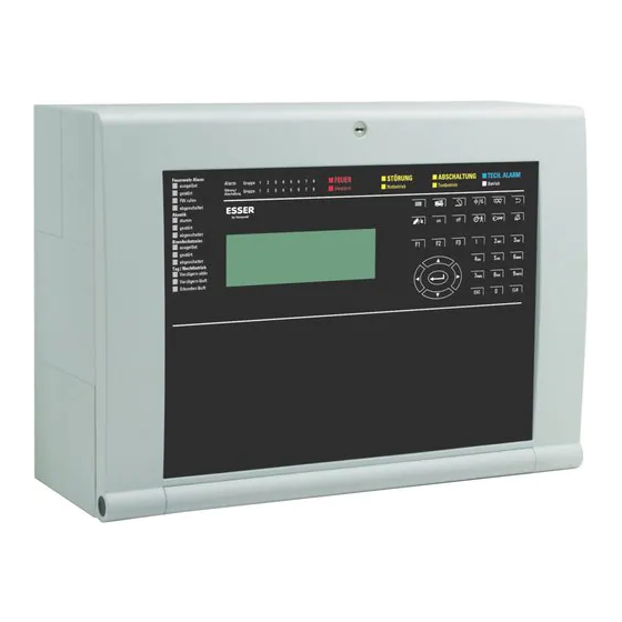
- Page 1 Commissioning Instruction Fire Alarm Control Panel Compact 798238.GB0 Technical changes reserved! G 212165 10.2014 / AB © 2014 Honeywell International Inc.
- Page 2 Fire Alarm Control Panel Compact Intended use This product may only be used for the applications outlined in the catalogue and the technical description and in combination with external devices and components which have been recommended or approved by us. Warning To ensure correct and safe operation of the product, all instructions concerning its proper transport, storage, installation and mounting must be observed and it must be operated with care.
-
Page 3: Table Of Contents
Fire Alarm Control Panel Compact Table of contents General / Application ..............................4 Preparing for commissioning ............................. 4 Installation of the programming software tools 8000 ..................5 Connection between the FACP and service PC ....................6 System configuration via panel keyboard ........................ 7 Display and keyboard ............................ -
Page 4: General / Application
Fire Alarm Control Panel Compact General / Application The operating and data entry sequences and also the contents of the display of the fire alarm control panel Compact are dependent on the installed software and programming and can also differ from the illustrations shown in this manual due to current software updates. -
Page 5: Installation Of The Programming Software Tools 8000
Fire Alarm Control Panel Compact Installation of the programming software tools 8000 When installing the programming software tools 8000 of version V1.16 or higher, it is also necessary to update the USB drivers for the PC interface. This update takes place automatically along with the installation. Fig. -
Page 6: Connection Between The Facp And Service Pc
Fire Alarm Control Panel Compact Connection between the FACP and service PC The service PC and the FACP are connected via USB for configuring / programming the FACP Compact. SLOT1 SLOT2 RS485 GND +24 V 1 2 3 4 5 6 1 2 3 4 5 6 1 2 3 4 5 6 7 8 9 10 11 12 13 14 15 16 17 18 19 20 21 22 23 24 25 26 27 28 29 30 31... -
Page 7: System Configuration Via Panel Keyboard
Fire Alarm Control Panel Compact System configuration via panel keyboard The FACP Compact is configured by using the programming software tools 8000. ® Quick and some usual temporary settings, excepted esserbus devices, may be configured via the display menu of the Fire Alarm Control Panel. Basically there are two different access levels to operate the FACP with level 3 (Installer) and 4 (System) features. - Page 8 Fire Alarm Control Panel Compact Navigation Function Selection of a menu item and branching off to submenus. For some menu items, the keys allow a direct selection (toggle function) for changing the configuration. In the case of menu items with value entry, the cursor jumps directly to the value to be PQRS WXYZ changed and the new value can then be entered directly.
-
Page 9: Memory Concept
Fire Alarm Control Panel Compact Memory concept The data processed during the configuration is always the customer data record that was loaded into the RAM memory. These are: the current customer data or the backup of the current customer data or ... -
Page 10: Access Authorisation
Fire Alarm Control Panel Compact Access authorisation Keyboard entry is inhibited during normal operation. Access is only possible at access level 2. ESSER by Honeywell 28.06.2012 12:00:00 Compact Fig. 7: Display during normal operation of the FACP Press key and enter the code for access level 2. -
Page 11: Service Menu
Fire Alarm Control Panel Compact main menu 1 information The main menu of the installer level is displayed after entry of 2 overview 3 operate the access code. 4 service 5 revision Fig. 10: Main menu of the installer level 1. -
Page 12: Event Log
Fire Alarm Control Panel Compact Event log Display of the event log The event log can be displayed at access level 3. The last 10,000 events, such as alarm, fault, switch-off, keyboard enable, are stored in the event log in chronological order. The last event is always displayed first. The events are automatically assigned with a message serial number. -
Page 13: Battery Information
Fire Alarm Control Panel Compact Battery information Information on the batteries of the emergency power supply is shown in the display. The permissible limit values are shown in the brackets. Select the >Refresh< function. battery information In this example, the current battery voltage is 26.9 V 1 refresh main board and in the permissible range of >... -
Page 14: Configuration
Fire Alarm Control Panel Compact Configuration The current configuration can be saved and the current data record can be edited with one of the 6 configurations (current, backup + 4 templates).The selected configuration will then be loaded into RAM. A query for the permanent saving of the edited configuration in RAM occurs when you exit the configuration menu. -
Page 15: Zone Menu
Fire Alarm Control Panel Compact Zone menu The menu of the 8 zones (1) allows the display of an overview of the configured zones and a programming of individual zones. configuration Konfiguration 1 zones 1 Gruppe 2 control zones 2 Steuergruppen - detector/transponder - Melder/Koppler 4 configuration... -
Page 16: Overview Zones< / >Overview< / >Select Single Assignment< Menu
Fire Alarm Control Panel Compact >Overview zones< / >Overview< / >Select single assignment< menu Select the zone with the 0-9 key. In the >Select single assignment< menu, an existing zone can be selected by searching with the left/right arrow keys or by directly entering the number with the panel keyboard. The additional text –... -
Page 17: Type Menu
Fire Alarm Control Panel Compact Type menu The desired zone type is selected in this menu. A zone type is always assigned certain functions and parameters. The currently selected type is marked with a tick in the >Type< zones sub-menu of a zone. - overview compact 2 overview 3 select single assignment... - Page 18 Fire Alarm Control Panel Compact 5.4.1 one-type control input If control input was selected as type, two functions can be defined for both the coming and going event. type 1 fire 2 techn. alarm 3 pre-alarm 4 fault 5 control input 6 system input 7 unused zone <-0021->...
- Page 19 Fire Alarm Control Panel Compact If system input was selected: type 1 fire 2 techn. alarm 3 pre-alarm 4 fault 5 control input 6 system input 7 unused function 1 ATU active 2 ATU fault 3 FPI activated 4 FPI fault 5 ESI activated 6 ESI fault 7 sound activated...
-
Page 20: Configuration
Fire Alarm Control Panel Compact Configuration The interfaces and the inputs and outputs of the mainboard are configured in this menu. Only the EDP protocol is implemented for the RS485 interface. configuration 1 zones 2 control zones - detector/transponder 4 configuration 5 settings 6 verify and save configuration... - Page 21 Fire Alarm Control Panel Compact 5.5.1 esserbus ® subscribers When the menu is selected a submenu appears with functions for replacing and configuring esserbus ® detectors. The esserbus ® subscribers must be configured using the service and programming software tools 8000. For information on the connection between the FACP and service PC, see Chapter 2.2. Mainboard 1 IN-4 : open / closed...
- Page 22 Fire Alarm Control Panel Compact Detector exchange mode 1 At the detector Exchange the detector in question connected to the loop. The primary loop 0114 installation location (loop) reports an error, as communication to the exchanged detector is no longer functioning.
- Page 23 Fire Alarm Control Panel Compact Detector exchange mode 2 At the FACP Enter the installer access code and switch on the primary loop. esserbus ® Open the menu 'configuration/mainboard / esserbus - wiring recognition 2 detector data assignment 3 detector exchange Open the menu 'detector exchange'.
-
Page 24: Single Assignment Atu Output Incl. Parallel Triggering
Fire Alarm Control Panel Compact Single assignment ATU output incl. parallel triggering The esserbus ® subscribers must be configured using the service and programming software tools 8000. The menus displayed here can be used for smaller temporary changes and may differ from the figures. - Page 25 Fire Alarm Control Panel Compact Trigger events *control zone >0006< 1 function type : ATU 2 hardware Trigger events 3 inverted : off 4 trigger events 5 pulse duration (s) : off 6 pulse latched : off 7 trigger prevention trigger events Event 1 1 event 1...
- Page 26 Fire Alarm Control Panel Compact 5.6.1 Hardware No hardware was programmed. Each control zone is usually hardware assigned one output. For example, OUT_1 is selected to trigger 1 location : not assigned the ATU. Each HW output can only be assigned one control zone – the plausibility check will otherwise show an error during data saving.
- Page 27 Fire Alarm Control Panel Compact 5.6.2 Fire protection equipment (FPE) / fire interface extinguishing (FIE) outputs configuration 1 zones 2 control zones Control zones - detector/transponder 4 configuration 5 settings 6 verify and save Steuergruppen control zones 1 Übersicht (Gesamt) 1 overview (all) Single assignment 2 Übersicht (AÜE)
- Page 28 Fire Alarm Control Panel Compact 5.6.3 Trigger programming configuration 1 zones 2 control zones Control zones - detector/transponder 4 configuration 5 settings 6 verify and save control zones 1 overview (all) 2 overview (ATU) 3 overview (sounder) Single assignment 4 overview (FPE/FIE) 5 select single assignment - multiple assignment control zone...
- Page 29 Fire Alarm Control Panel Compact event 2 Event 2 1 type : none type 1 none 2 panel state Type 3 activation zone(s) 4 activation detector(s) 5 fault zone(s) 6 fault detector(s) 7 deactivation zone(s) *event 2 1 type : activation zone(s) Activation zone(s) 2 range from 3 range to...
- Page 30 Fire Alarm Control Panel Compact 5.6.4 Trigger prevention setting control zone >0003< 1 function type : common 2 hardware Trigger prevention 3 inverted : off 4 trigger events 5 pulse duration (s) : off pulse latched : off 7 trigger prevention PQRS tigger prevention 1 operation access level 2...
- Page 31 Fire Alarm Control Panel Compact 5.6.6 Output delay configuration A delay cannot be configured for the individual control zone because it is configured via the function type. If the function type is, for example, ATU and the assigned zone has the ‚ATU delayed‘ property, the relay will be activated with a delay.
-
Page 32: Settings
Fire Alarm Control Panel Compact Settings settings 1 display functions 2 system timings 3 control timings 4 language Fig. 44: >Settings< menu screen Display functions display functions 1 descript. : [panel 1 2 code installer : 123 3 code operation : 0123 code cust. - Page 33 Fire Alarm Control Panel Compact 6.1.1 Panel name assignment A name or building-specific description (25 characters max.) for display functions the fire alarm control panel can be entered with the ‘description’ 1 descript. : [panel 1 2 code installer : 123 menu item.
-
Page 34: System Timings
Fire Alarm Control Panel Compact System timings System-dependant switching times can be configured in this menu. System timings 1 daylight saving time : on 2 daylight saving start: 30.03.15 02:00 Menu page 1 of 2 3 daylight saving end : 26.10.15 02:00 - delay common fault (min) : 00 5 delay mains fault (min) : 030... - Page 35 Fire Alarm Control Panel Compact Delay on common fault in minutes A system common fault message will be suppressed for the set system timings time (00-99 minutes). No message display or activation will 1 daylight saving time : on 2 daylight saving start: 25.03.12 02:00 occur during this time.
- Page 36 Fire Alarm Control Panel Compact 6.2.1 Delay time / verification time This function allows a delayed activation of the transmission unit (ATU) and the alarm signalling devices and fire protection equipment in the day mode of the FACP. This function can be used, for example, for areas and buildings in which persons are present and who can, in the event of a fire alarm, prevent a direct alerting by pressing the >verification<...
-
Page 37: Switching Times
Fire Alarm Control Panel Compact Switching times settings 1 display functions 2 system timings Select control timings with the key. 3 switching timings 4 language switching timings 1 overview The switching timings are divided into an overview of the 2 special days programmed switching times and a menu for programming special days. -
Page 38: Special Days
Fire Alarm Control Panel Compact Special days This menu allows you to define up to 14 special days. “Special days” are days on which the FACP should operate with switching times different to those of “normal weekdays”. overview special days Display of the special days stored in the system. -
Page 39: Verify And Save
Fire Alarm Control Panel Compact 6.4.1 Language selection The language for the system text shown in the display can be selected in this menu. settings 1 display functions 2 system timings Select language menu item with the key. 3 switching timings 4 language Select the desired language with the digit keys. -
Page 40: Revision Menu
Fire Alarm Control Panel Compact Revision menu This function allows service work on the fire alarm control panel without triggering an external alerting. main menu 1 information 2 overview 3 operate 4 service 5 revision Select the >Revision< function with the key. -
Page 41: Programming An Output As 'Unused
Fire Alarm Control Panel Compact Programming an output as ‘unused’ This function allows an output (control zone) to be configured as >unused<. Outputs with the >unused< function type are not activated. configuration 1 zones 2 control zones >Configuration< menu item - detector/transponder 4 configuration 5 settings... -
Page 42: Deactivation Of Fip / Fop Activation
Fire Alarm Control Panel Compact Deactivation of FIP / FOP activation This function allows the deactivation of an FIP / FOP (Fire Brigade Indicating Panel / Fire Brigade Operating Panel). These devices are connected to the RS485 interface of the fire alarm control panel. Devices connected to this interface are not activated when the RS485 interface is switched off (i.e. -
Page 43: Fault Diagnosis And Correction
Fire Alarm Control Panel Compact Fault diagnosis and correction Battery fault 1. battery fault 14:45 12.08 low voltage Example: battery fault warning code entry Enter access code code: **** Code main menu 1 information Main menu 2 overview 3 operate 4 enter access level 3 service 1 access level 3... -
Page 44: Zone Fault
Fire Alarm Control Panel Compact Zone fault 1. trouble zone:0001 14:45 12.08 text Example: Fault warning for detector zone (here zone 0001) wire break code entry Enter access code code: **** Code main menu Main menu 1 information 2 overview 3 operate 4 enter access level 3 operate... -
Page 45: Atu Fault / Acoustic Fault / Fpe Fault
Fire Alarm Control Panel Compact ATU fault / Acoustic fault / FPE fault The example shows an ATU fault. Acoustic and FPE faults are shown similarly. 1. trouble control:0005 14:45 12.08 alarm MB ATU fault warning wire break code entry code: **** Enter access code... -
Page 46: Templates
Fire Alarm Control Panel Compact Templates The factory settings for the fire alarm control panel and the available templates are given in the tables on the following pages. The settings and templates can be changed and adjusted to suit the object. If the fire alarm control panel is reset to the factory settings, all changes are discarded and the original data is reloaded. - Page 47 Fire Alarm Control Panel Compact House alarm Trigger/switching Text TYPE Monitoring function IN_1 Acoustics fault System input Acoustics fault IN_2 Dialler fault Fault IN_3 FPE fault System input FPE fault IN_4 FPE triggered System input FPE triggered OUT1 Common fire General Panel state fire OUT2...
- Page 48 Novar GmbH a Honeywell Company Dieselstraße 2, D-41469 Neuss Internet: www.esser-systems.com Telefon: +49 (0) 21 31 / 406 15 - 600 E-Mail: info@esser-systems.com Telefax: +49 (0) 21 31 / 406 15 - 286...