
Related Manuals for Cisco C880 M5


Summary of Contents for Cisco C880 M5
- Page 1 Cisco C880 M5 Installation Manual December 2017 Americas Headquarters Cisco Systems, Inc. 170 West Tasman Drive San Jose, CA 95134-1706 USA http://www.cisco.com Tel: 408 526-4000 800 553-NETS (6387) Fax: 408 527-0883...
- Page 2 CISCO OR ITS SUPPLIERS HAVE BEEN ADVISED OF THE POSSIBILITY OF SUCH DAMAGES. Cisco and the Cisco logo are trademarks or registered trademarks of Cisco and/or its affiliates in the U.S. and other countries. To view a list of Cisco trademarks, go to this URL: www.cisco.com/go/trademarks. Third-party trademarks mentioned are the property of their respective owners.
-
Page 3: Table Of Contents
Installation requirements ............38 5.5.2 Input power connection specification ........41 5.5.3 Connecting diagram of the power cord ........42 5.5.4 Connecting procedure of the power cord ........44 Notes on connecting/disconnecting cables ........45 Cisco C880 M5 Installation manual... - Page 4 Flickering stripes on monitor screen..........78 No screen display or display drifts ..........79 Incorrect date and time ..............79 Drives reported as "dead" when starting system ......79 Added drive reported as defective ..........80 Appendix ....................81 Cisco C880 M5 Installation Manual...
- Page 5 Bus Number .................. 81 Correspondence between PHP Slot and Slot Numbers ....84 Device Path ................... 84 Replacement of PCIe SSD SFF Slot Number ......85 DIMM installation order ..............86 Component Layout ................ 87 Cisco C880 M5 Installation manual...
-
Page 6: Preface
1 Preface The scalable Cisco C880 M5 is an Intel-based rack server for critical company scenarios, e.g. as database management system for medium or large-sized databases or as a consolidation basis to run an immensely large number of different applications using virtualization technologies. -
Page 7: Notational Conventions
CAUTION! pay particular attention to texts marked with this symbol. Failure to observe this warning may endanger your life, destroy the system or lead to the loss of data. indicates additional information, notes and tips. Cisco C880 M5 Installation manual... -
Page 8: Functional Overview
– Hot-plug power supply units For information on replacing these components, see "Cisco C880 M5 Administration Guide". CSS indicators on the control panel and on the back of Cisco C880 M5 server provide you with information if a CSS event arises. System Board The features of the System Board are described in "Cisco C880 M5... - Page 9 The PDA (Prefailure Detection and Analyzing) technology analyzes and monitors all components that are critical for system reliability. The SAS controller card supports the RAID levels 0, 1, 1E, 5, 6, 10, 50 and 60 thus increasing system availability and improving reliability. Cisco C880 M5 Installation manual...
- Page 10 Additional reliability is provided by the hot-plug HDD/SSD modules, fans and power supply units. Cisco C880 M5 Installation Manual...
- Page 11 Management Controller (BMC) with integrated management LAN connector and expanded functionality that was previously only available with additional plug-in cards. In this way, the iRMC S5 enables complete control of Cisco C880 M5, regardless of system status, and thus particularly the control of Cisco C880 M5 that are in the "out-of-band"...
- Page 12 • Cisco C880 M5 Administration Guide Service and support Cisco C880 M5 are easy to maintain and modular, thus enabling quick and simple maintenance. The handles and locks (touch points) used to exchange components are colored green to ensure simple and immediate recognition.
- Page 13 Remote Management Remote Management is the remote management solution for Cisco C880 M5. Remote Management and the relevant hardware components integrated on the System Board allow remote monitoring and maintenance as well as fast restoration of operation in the event of errors.
-
Page 14: Server Specification
Memory notes At least 4 DIMMs have to be installed on System Board. (24 DIMM slots per System Board). Notes on memory Memory modules will be delivered in sets of module 2 DIMMs per order code. Cisco C880 M5 Installation Manual... - Page 15 2 x M.2 SSD as option connected by SATA interface RAID 0/1/10 support Slots Table 2.7 Specification of Slots PCI-Express Gen3 x8 8 x half length / Low Profile PCI-Express Gen3 x16 8 x half length / Low Profile Cisco C880 M5 Installation manual...
- Page 16 /h) x: Rotational speed of FAN#0(rpm) y = 5E-06x - 0.0203x + 113.26 Operating Panel Table 2.10 Specification of Operating Panel Operating buttons Power button Reset button Location button NMI button Status LEDs System Power (green) System Alarm (orange) Cisco C880 M5 Installation Manual...
- Page 17 EN 60721 / IEC 721 Part 3-2 Temperature: Operation (3K2) 5°C ... 35°C (without ATD) 5°C ... 40°C (with ATD) -25°C ...60°C Transport (2K2) Humidity 10% ... 85% (non condensing) Condensation during operation must be avoided! Cisco C880 M5 Installation manual...
- Page 18 Sound power level L < 5.2 B (standby) < 8.0 B (operation) (ISO 9296, at < 25°C) Sound pressure level at bystander position L < 43 db(A) (standby) (ISO 9296, at < 25°C) < 61 db(A) (operation) Cisco C880 M5 Installation Manual...
- Page 19 The server is connected to the mains with 2 cords as a minimum or up to 4 cords as a maximum for redundant operation. Each cord connection requires an appropriate fuse in building installation (see above). Earthed socket outlets have to be used (protection class I device). Cisco C880 M5 Installation manual...
- Page 20 CNS 13438: Class A China (Not covered) Japan VCCI Class A / JEITA Korea KN 32 / KN 25 Low Voltage Directive 2014/35/EU CE marking to EU directives Electromagnetic compatibility 2014/30/EU Restriction of hazardous substances 2011/65/EU Cisco C880 M5 Installation Manual...
-
Page 21: Installation Steps, Overview
30). Familiarize yourself with the controls and indicators on the front of the server (see "Starting up and operation" on page 46). Install the operating system and applications on the server. Cisco C880 M5 Installation manual... -
Page 22: Important Information
Material damage may be caused to the server if this requirement is not met. Only transport the server in the original packaging or in packaging ● that protects it from impacts and jolts. Cisco C880 M5 Installation Manual... - Page 23 If you cause a defect on the device by installing or exchanging system ● extensions, the warranty will be invalidated. Only set the resolutions and refresh rates specified in the operating ● manual for your monitor. Otherwise, you may damage the monitor. If Cisco C880 M5 Installation manual...
- Page 24 Under certain circumstances, sharp CD/DVD/BD fragments can pierce the cover of the optical drive (equipment damage) and can fly out of the device (danger of injury, particularly to uncovered body parts such as the face or neck). Cisco C880 M5 Installation Manual...
- Page 25 Do not store CDs/DVDs/BDs at high temperatures. Areas exposed to ● prolonged direct sunlight or near heating appliances are to be avoided. You can prevent damage from the optical drive and the CDs/DVDs/BDs, Cisco C880 M5 Installation manual...
- Page 26 Always hold components with ESDs at the edges or at the points marked ● green (touch points). Do not touch any connectors or conduction paths on an ESD. ● Place all the components on a pad which is free of electrostatic charge. ● Cisco C880 M5 Installation Manual...
-
Page 27: Ce Conformity
Canadian Interference-Causing Equipment Standard ICES-003 for digital apparatus. These limits are designed to provide reasonable protection against harmful interference in a residential installation. This equipment generates, uses and can radiate radio frequency energy and, if not Cisco C880 M5 Installation manual... -
Page 28: Transporting The Server
Consult the dealer or an experienced radio/TV technician for help. ● Cisco is not responsible for any radio or television interference caused by unauthorized modifications of this equipment or the substitution or attachment of connecting cables and equipment other than those specified by Cisco. The correction of interferences caused by such unauthorized modification, substitution or attachment will be the responsibility of the user. -
Page 29: Environmental Protection
2002/96/EC on waste electrical and electronic equipment (WEEE). This directive sets the framework for returning and recycling used equipment and is valid across the EU. When returning your used device, please use the return and collection systems available to you. Cisco C880 M5 Installation manual... -
Page 30: Hardware Installation
(outside, transport or storage temperature). Check environmental temperature conditions. the server can be ● installed as locations that satisfy the environmental conditions listed Table 2.12 on page 17 Table 2.13 on page Cisco C880 M5 Installation Manual... -
Page 31: Setup Workflow
Start the system and confirm that it has started normally. - Saving setting information Save the setting information for iRMC. Installing the OS and Install the operating system and bundled software. bundled software. Cisco C880 M5 Installation manual... -
Page 32: Work Performed By A Field Engineer
Installing a rack (installation of earthquake-resistant kits etc. is within the ● scope of field engineer's work) Rack mounting of the device of 20kg or more to a height of 25U or more, or ● rack mounting of the device of 60 kg or more Cisco C880 M5 Installation Manual... -
Page 33: Unpacking The Server
Rack system requirements The rack systems from Cisco R Series Racks and 19-inch standard rack support the installation of Cisco C880 M5. Installation in most current rack systems from other manufacturers (3rd party racks) is also supported. To accommodate the ventilation concept and ensure proper ventilation, any unused areas in the rack must be sealed using dummy covers. - Page 34 D Cable routing area (cable area depth) and ventilation E Space for front panel and ventilation Space for right and left support systems P Cisco C880 M5 rack installation depth a1 Front left support upright a2 Front right support upright...
- Page 35 Figure 5.1 Mechanical requirement Cisco C880 M5 Installation manual...
- Page 36 (air flow from the front to the rear). – Power supply: For installation in third party racks, you must ensure that the appropriate socket strips are present. Cisco C880 M5 Installation Manual...
-
Page 37: Connecting Devices To The Server
Plug the data cable for the monitor into the video connector on the front of SB#0. Connect the power cord of the monitor to a grounded mains outlet of the in- house mains and/or into the mains socket strip of the rack. Cisco C880 M5 Installation manual... -
Page 38: Connecting The Server To The Mains
AC source (e.g. uninterruptable power supply (UPS)). Refer to tables below for maximum DC loading for both AC redundant and AC non redundant configurations. Cisco C880 M5 Installation Manual... - Page 39 (200-240V): 3222W 2+1 (3 PSUs) 2+2 (4 PSUs) Two power supply modules are capable of handling the maximum power requirements for a fully configured Cisco C880 M5 server system, which include the following: Eight processors ● 12 TB of memory ●...
- Page 40 (2+0) (200-240V): 3 PSUs 3222W connected to mains (2+1) (200-240V): 2 PSUs (200-240V): 4 PSUs 3222W 3222W connected to connected to mains mains (2+2) 2 PSUs connected to an isolated AC source e.g. UPS (2+2) Cisco C880 M5 Installation Manual...
-
Page 41: Input Power Connection Specification
5.5.2 Input power connection specification Table 5.6 Input power connection specification Plug format Destination Recipient outlet format IEC60320-C20 type Power distribution box IEC60320-C19 type Cisco C880 M5 Installation manual... -
Page 42: Connecting Diagram Of The Power Cord
To make the power supply redundant, it is necessary to arrange three PSUs and three power supply cables (200 V NEMA L 6 - 20 P). Figure 5.4 Connecting Diagram of PSU Redundant(2+1) PSU#3 PSU#1 PSU#2 PSU#0 Cisco C880 M5 Installation Manual... - Page 43 To make the power supply redundant, it is necessary to arrange four PSUs and four power supply cables (200 V NEMA L 6 - 20 P). Figure 5.6 Connecting Diagram of PSU Redundant(2+2) with AC Redundant PSU#3 PSU#1 PSU#2 PSU#0 Cisco C880 M5 Installation manual...
-
Page 44: Connecting Procedure Of The Power Cord
Now the insulated connector cannot be accidentally disconnected from the server. Connect the mains plug to a grounded mains outlet in the in-house power supply network or a power outlet of the socket strip in the rack (see Technical Manual for the rack). Cisco C880 M5 Installation Manual... -
Page 45: Notes On Connecting/Disconnecting Cables
Notes on inserting/removing units Please power off the system and remove the power cords from PSUs in the chassis before inserting or removing System Board, IOUB, DU_SAS, DU_PCIE, MGMT-LANU or PCIe card except PHP slot to/from the chassis. Cisco C880 M5 Installation manual... -
Page 46: Starting Up And Operation
Figure 6.1 on page 46) as far as it will go and push it back in again. The ID card contains various system information, such as the product name, serial number, order number, MAC addresses and DNS name. Cisco C880 M5 Installation Manual... - Page 47 This button highlights System Location indicator on Location button the front and I/O panels for easy server identification. This button is used to switch the server on or off. Power button If the system is running an ACPI-compliant operating Cisco C880 M5 Installation manual...
- Page 48 – the system is in power-off mode but connected to the mains (AC- connected) green on AC-connected – the system has been switched on and is in power-on delay After connecting the server to the mains it takes about 60 seconds Cisco C880 M5 Installation Manual...
- Page 49 Status Description until the server enters the standby mode. is off in the following cases: – the system is not connected to the mains – the system is powered on and in normal operation (S0) Cisco C880 M5 Installation manual...
- Page 50 – Lights up: System Board Power On – Does not light: System Board Power Off Alarm (orange) – Does not light: no System Board error – Lights up: System Board error Location (Blue) – Lights up: System Board Identification Cisco C880 M5 Installation Manual...
- Page 51 Power (green) – Lights up: DU_SAS Power On – Does not light: DU_SAS Power Off Alarm (orange) – Does not light: no DU_SAS – Lights up: DU_SAS error Location (Blue) – Lights up: DU_SAS Identification. Cisco C880 M5 Installation manual...
- Page 52 Power (green) – Lights up: DU_PCIE Power On – Does not light: DU_PCIE Power Off Alarm (orange) – Does not light: no DU_PCIE error – Lights up: DU_PCIE error Location (Blue) – Lights up: DU_PCIE Identification Cisco C880 M5 Installation Manual...
- Page 53 – Slow flashing: HDD/SSD Rebuild (the data is being restored after changing a drive) If a hard disk drive or solid state disk continuously indicates an error, the drive should be replaced as soon as possible. This can be done during operation. Cisco C880 M5 Installation manual...
- Page 54 PCIe SSD SFF module is not correctly inserted) – Flashing: PCIe SSD SFF location identification If a PCIe SSD SFF module continuously indicates an error, the drive should be replaced as soon as possible. This can be done during operation. Cisco C880 M5 Installation Manual...
-
Page 55: Rear Of Server
6.1.2 Rear of server 6.1.2.1 Indicators on IOUB Figure 6.8 Indicators on IOUB Table 6.9 Operations of indicators on IOUB Alarm (Orange) – Lights up: IOUB error – Does not light up: no IOUB error Cisco C880 M5 Installation manual... - Page 56 – Lights up: System Power On – Does not light up: AC Off and System Power Off PCI Slot Alarm (Orange) – Lights up: IOUB PCI card slot error – Does not light up: no IOUB card slot error Cisco C880 M5 Installation Manual...
- Page 57 6.1.2.3 Indicators on MGMT_LANU Figure 6.10 Indicators on MGMT_LANU Management Shared Port Port Table 6.11 Operations of indicators on MGMT_LANU Alarm (Orange) – Lights up: MGMT_LANU error – Does not light up: no MGMT_LANU error Cisco C880 M5 Installation manual...
- Page 58 – Lights up (Orange): Non-Redundant Power supply system in PSU failed – Lights up (Orange): PSU identification – Flashing (Green): AC input On and System Power Off – Does not light up: AC input of PSU Off Cisco C880 M5 Installation Manual...
- Page 59 6.1.2.5 Indicator on FANU Figure 6.12 Indicators on FANU Table 6.13 Operations of indicators on FANU Alarm (Orange) – Lights up (Orange): FANM error – Lights up (Orange): FANU identification – Does not light up: no FANM error Cisco C880 M5 Installation manual...
-
Page 60: Switching The Server On And Off
"Safety Precautions". When operating the device outside of this operating environment, the server may operate improperly, damage data etc. Furthermore, Cisco cannot be held responsible for any related damage, malfunction, or loss of data, etc. Be sure to wait for 10 seconds or more after shutdown before turning ●... - Page 61 There is a risk that data may be lost. iRMC S5 iRMC S5 offers various options for switching the server on and off, e.g. via the Power On Off page of the iRMC S5 Web interface. Cisco C880 M5 Installation manual...
-
Page 62: Configuring The Server
Make sure that the energy saving functions are disabled in the BIOS Setup during server operation. 6.3.1 Configuring Fast Boot If Fast Boot is set to Enable in BIOS setup, startup times may differ even on the same device. Cisco C880 M5 Installation Manual... -
Page 63: Configuring Memory Mirror
6.3.2 Configuring Memory Mirror In Cisco C880 M5, Full Mirror Mode and Address Range Mirror Mode are supported as the memory mirror, in which the function with the CPU is used. Full Mirror/Address Range Mirror can be selected from iRMC Web-UI. - Page 64 If you use Address Range Mirror mode, you must boot OS with UEFI. If you boot OS with Legacy, OS does not aware Address Range Mirror mode. There is no setting about Memory Mirror RAS for Address Range Mirror mode. Cisco C880 M5 Installation Manual...
- Page 65 Memory region used by the kernel is limited to mirrored region. Depending on the system operation, memory which can be used by the kernel may be insufficient and system may not run normally. In that case, increase mirror size. Cisco C880 M5 Installation manual...
-
Page 66: Back Up And Restore Raid Configuration Via Rest Api
Following description shows back up and restore RAID configuration via REST API. Using curl in following example. If changed the RAID configuration after back up, please back up again, and restore with the same RAID configuration when backing up. Cisco C880 M5 Installation Manual... - Page 67 C:\curl –u admin:admin –H “Accept: application/json” –X POST –i http://172.17.167.219/rest/v1/Oem/eLCM/ProfileManagement/get?PARAM_ PATH=Server/HWConfigurationIrmc/Adapters/RAIDAdapter [Response] HTTP/1.1 202 Accepted rest/v1/Oem/eLCM/ProfileManagement/RAIDAdapter Data: Tue, 08 Dec 2015 09:18:49 GMT Server: iRMC S5 Webserver Content-Length: 139 Content-Type: application/json; charset=UTF-8 “Session”:{ “id”:5, “WorkSequence”:”obtainProfileParameters”, “Start”:””, “Duration”:0, “Status”:”activated” Cisco C880 M5 Installation manual...
- Page 68 [Response] HTTP/1.1 200 OK Data: Tue, 08 Dec 2015 09:28:54 GMT Server: iRMC S5 Webserver Content-Length: 865 Content-Type: application/json; charset=UTF-8 Content-disposition: attachment; filename=”rest/v1/Oem/eLCM/ProfileManagement/RAIDAdapter” “Server”:{ “HWConfigurationIrmc”:{ “Adapters”:{ “RAIDAdapter”:[ “@AdapterId”:”RAIDAdapter1”, “@ConfigurationType”:”Addressing”, PhysicalDisks:{ PhysicalDisk:[ “@Number”:”0”, “Slot”:”0”, “PDStatus”:”Available”, “Interface”:”SAS”, Cisco C880 M5 Installation Manual...
- Page 69 To delete the profile from the profile store you should use. [Command] C:\>curl –u admin:admin –H “Accept: application/json” –X DELETE –i http://172.17.167.219/rest/v1/Oem/eLCM/ProfileManagement/RAIDAdapter [Response] HTTP/1.1 200 OK Date: Tue, 08 Dec 2015 09:18:56 GMT Server: iRMC S5 Webserver Transfer-Encoding: chunked Content-Type: application/json; charset=UTF-8 Cisco C880 M5 Installation manual...
- Page 70 You will create a Raid profile in the Profile store again, and retrieve it. Then, you will find a new configuration according to the result of your Raid operation. The profile is reflected immediately when the command is executed. Rebooting is unnecessary. Cisco C880 M5 Installation Manual...
-
Page 71: Configuring The Server And Installing The Operating System
Follow the instructions on screen and in the manual for the operating system. 6.3.5 Configuring Cougar5(EP540i) When using Cougar5 in Legacy mode, please set "Launch Storage OpROM policy" in BIOS menu to "UEFI Only". Cisco C880 M5 Installation manual... -
Page 72: Cleaning The Server
Clean the keyboard and the mouse with a disinfecting cloth. Wipe the server and monitor casing with a dry cloth. If particularly dirty, use a cloth that has been moistened in a mild domestic detergent and then carefully wrung out. Cisco C880 M5 Installation Manual... -
Page 73: Setting Of Boot Watchdog Before And After Firmware Update Of I/O Card
Check the box for [Enable Boot Watchdog]. Rebuilding Software RAID after exchanging M.2 SSD To rebuild Software RAID of M.2 SSD after exchanging one of them in Red Hat Enterprise Linux, please use mdadm command. Cisco C880 M5 Installation manual... -
Page 74: Hot-Plug Procedure
By this operation, you can remove the device associated with the relevant adapter from the system. Example: Making the PCI Express slot with PCI Express slot number 20 power off # echo 0 > /sys/bus/pci/slots/20/power Replace the PCI card. Cisco C880 M5 Installation Manual... -
Page 75: Addition Procedure
Press Attention Button on the PCI slot where the target PCI card is installed. Confirm the power status of the added PCI card by the procedure of step2 "Replacement procedure of Red Hat Enterprise Linux/ SUSE Linux Enterprise Server" on page Cisco C880 M5 Installation manual... -
Page 76: Property And Data Protection
By combining these options you can achieve optimum protection for your system. A detailed description of the Security menu and how to assign passwords can be found in "Cisco C880 M5 BIOS Setup Guide". Cisco C880 M5 Installation Manual... -
Page 77: Troubleshooting And Tips
System Power indicator remains dark after the server has been connected to mains. Power cable incorrectly connected Make sure that the power cable(s) is/are correctly connected to the server and the grounded power outlet(s). Cisco C880 M5 Installation manual... -
Page 78: Screen Remains Blank
Refer to the documentation for your operating system or the software for the screen controller for details of how to set the correct horizontal frequency for your monitor, and follow the procedure accordingly. Cisco C880 M5 Installation Manual... -
Page 79: No Screen Display Or Display Drifts
If the date and time are still wrong after the server has been switched off and back on again, replace the lithium battery (for a description refer to the "Cisco C880 M5 BIOS Setup Guide") or contact our customer service team. -
Page 80: Added Drive Reported As Defective
Information is provided in the documentation for the RAID controller. Remove and reinstall the drive while the system is switched ON. If the drive continues to be shown as defective, then replace it. Cisco C880 M5 Installation Manual... -
Page 81: Appendix
PCIe SSD SFF#0 S#00:B#13:D#00:F#00 PCIe SSD SFF#1 S#00:B#16:D#00:F#00 PCIe SSD SFF#2 S#00:B#15:D#00:F#00 PCIe SSD SFF#3 S#00:B#71:D#00:F#00 DU_SAS#1 RAID Card S#00:B#71:D#00:F#00 DU_PCIE#1 Switch Card S#00:B#74:D#00:F#00 PCIe SSD SFF#0 S#00:B#73:D#00:F#00 PCIe SSD SFF#1 S#00:B#76:D#00:F#00 PCIe SSD SFF#2 Cisco C880 M5 Installation manual... - Page 82 Board Port/Slot Bus Number(Hex) S#00:B#75:D#00:F#00 PCIe SSD SFF#3 Cisco C880 M5 Installation Manual...
- Page 83 PCIe SSD SFF#1 0000:13:00.0 PCIe SSD SFF#2 0000:16:00.0 PCIe SSD SFF#3 0000:15:00.0 DU_SAS#1 RAID Card 0000:71:00.0 DU_PCIE#1 Switch Card 0000:71:00.0 PCIe SSD SFF#0 0000:74:00.0 PCIe SSD SFF#1 0000:73:00.0 PCIe SSD SFF#2 0000:76:00.0 PCIe SSD SFF#3 0000:75:00.0 Cisco C880 M5 Installation manual...
-
Page 84: Correspondence Between Php Slot And Slot Numbers
Device Path (Hex) PcieRoot(0x1)/Pci(0x0,0x0)/Pci(0x0,0x0) IOUB#0 Slot#0 PcieRoot(0x1)/Pci(0x2,0x0)/Pci(0x0,0x0) Slot#1 PcieRoot(0x11)/Pci(0x0,0x0)/Pci(0x0,0x0) Slot#2 PcieRoot(0x12)/Pci(0x0,0x0)/Pci(0x0,0x0) Slot#3 PcieRoot(0x21)/Pci(0x0,0x0)/Pci(0x0,0x0) Slot#4 PcieRoot(0x21)/Pci(0x2,0x0)/Pci(0x0,0x0) Slot#5 PcieRoot(0x22)/Pci(0x0,0x0)/Pci(0x0,0x0) Slot#6 PcieRoot(0x31)/Pci(0x0,0x0)/Pci(0x0,0x0) Slot#7 PcieRoot(0x41)/Pci(0x0,0x0)/Pci(0x0,0x0) IOUB#1 Slot#0 PcieRoot(0x41)/Pci(0x2,0x0)/Pci(0x0,0x0) Slot#1 PcieRoot(0x51)/Pci(0x0,0x0)/Pci(0x0,0x0) Slot#2 PcieRoot(0x52)/Pci(0x0,0x0)/Pci(0x0,0x0) Slot#3 PcieRoot(0x61)/Pci(0x0,0x0)/Pci(0x0,0x0) Slot#4 PcieRoot(0x61)/Pci(0x2,0x0)/Pci(0x0,0x0) Slot#5 PcieRoot(0x62)/Pci(0x0,0x0)/Pci(0x0,0x0) Slot#6 PcieRoot(0x71)/Pci(0x0,0x0)/Pci(0x0,0x0) Slot#7 Cisco C880 M5 Installation Manual... -
Page 85: Replacement Of Pcie Ssd Sff Slot Number
About installation location of PCIe SSD SFF installed in DU_PCIE, you need to replace the PCIe SSD SFF number displayed on iRMC Web-UI and SeverView with actual installation location. Table 9.4 Replacement of PCIe SSD SFF Slot Number PCIe SSD PCIe SSD SFF Slot SFF# number (iRMC) Cisco C880 M5 Installation manual... -
Page 86: Dimm Installation Order
3 and cannot be installed after number 4. (*4) Only when the CPU which memory capacity is 768GB and 128GB DIMM are installed together, this installation order is applied. Cisco C880 M5 Installation Manual... -
Page 87: Component Layout
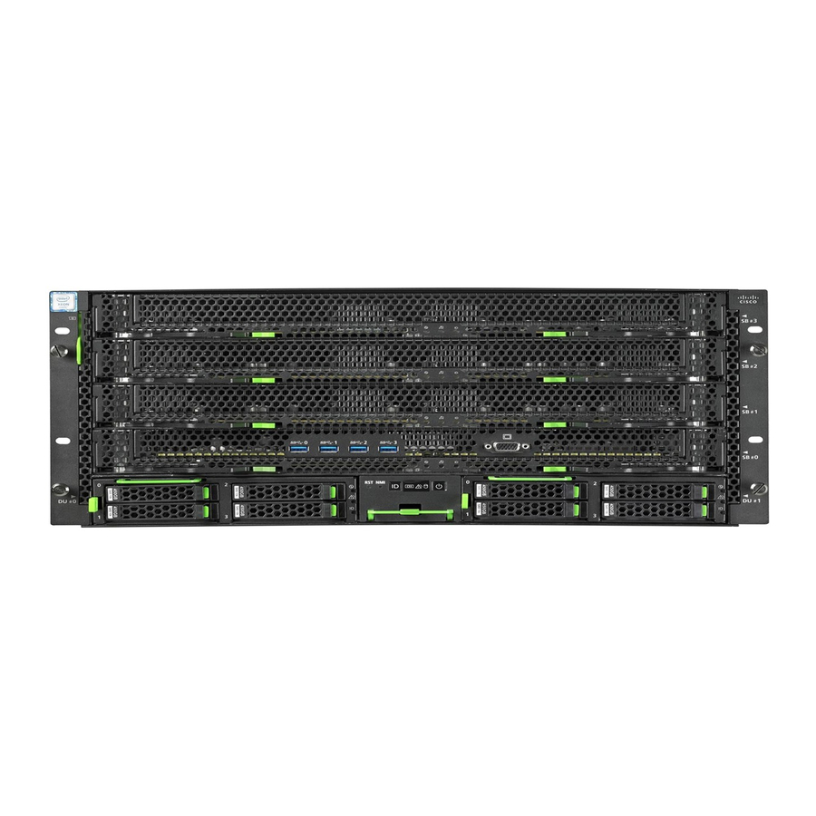
Figure 9.1 Component Layout (Front) SB#3 SB#2 SB#1 SB#0 HDD/SSD#0 HDD/SSD#2 HDD/SSD#0 HDD/SSD#2 Operation Panel HDD/SSD#1 HDD/SSD#3 HDD/SSD#1 HDD/SSD#3 DU_SAS/DU_PCIE#0 DU_SAS/DU_PCIE#1 Figure 9.2 Component Layout (Rear) IOUB#1 PSU#1 PSU#3 FANU#5 FANU#2 IOUB#0 FANU#4 FANU#1 FANU#3 FANU#0 PSU#0 PSU#2 MGMT_LANU Cisco C880 M5 Installation manual...