Advertisement
Quick Links
Server Setup
This chapter provides instructions for setting up the server. It includes the following topics:
•
•
•
•
•
Connect Power Supplies and KVM Adapter
To begin, connect both power supplies on the back of your appliance. Connect the included KVM adapter to
an external monitor and keyboard, and plug into the KVM port located at the front of the server, as illustrated
in Figure 3.
If CIMC is configured, you can use a remote KVM. See
Refer to the server product documentation for detailed hardware and environmental setup information (See
Product
Network Interface Connections Setup
The SFP+ modules must be connected to the chassis before the appliance is powered on for the session in
which the configuration wizard is going to be run. However, wiring the SFP up to the network can be done
between power on and configuration.
Note
For Threat Grid Appliance (version 2.7.2 or later), only the Threat Grid M5 Appliance is supported. Refer to
the
Cisco Threat Grid M5 Appliance Hardware Installation Guide
C220 M3 Rack Server Setup
The interfaces must be properly connected and configured for the appliance to operate.
Connect Power Supplies and KVM Adapter, on page 1
Network Interface Connections Setup, on page 1
Network Interface Setup Diagram, on page 4
Firewall Rules, on page 5
Power On and Boot Up Appliance, on page 8
Documentation).
CIMC
Configuration.
for server setup instructions.
Server Setup
1
Advertisement

Related Manuals for Cisco C220 M3


Summary of Contents for Cisco C220 M3
- Page 1 Note For Threat Grid Appliance (version 2.7.2 or later), only the Threat Grid M5 Appliance is supported. Refer to Cisco Threat Grid M5 Appliance Hardware Installation Guide for server setup instructions. C220 M3 Rack Server Setup The interfaces must be properly connected and configured for the appliance to operate.
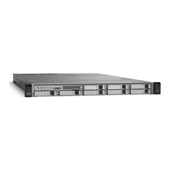
- Page 2 Find the two SFP+ ports and three Ethernet ports on the back of the appliance and attach the network cables as illustrated in Figure 4. Reserved is the non-Admin SFP+ port that is reserved for future use. Figure 1: Cisco UCS C220 M3 SFF Rack Server Figure 2: Cisco UCS C220 M3 Rear View Details Server Setup...
- Page 3 The interfaces must be properly connected and configured for the appliance to operate. Use port 3 Slot 2 for the (optional) Clust interface. Note The details for your appliance may differ from the illustrations. Contact support@threatgrid.com if you have any questions. Figure 3: Cisco UCS C220 M4 SFF Rack Server Server Setup...
- Page 4 Server Setup Network Interface Setup Diagram Figure 4: CIsco UCS C220 M4 Rear View Details Connections: • 1 Admin, Clust • 8 (left) Clean • 8 (right) Dirty • 6 CIMC Network Interface Setup Diagram This section describes the most logical and recommended setup for a Threat Grid Appliance. However, each customer's interface setup is different.
-
Page 5: Firewall Rules
Server Setup Firewall Rules Figure 5: Network Interfaces Setup Diagram Note In Threat Grid Appliance (v2.7.2 and later), there is also the enable_clean_interface option, which is disabled by default. This option (after applying configuration and rebooting) enables access to the administrative interface on port 8443 of the assigned clean IP. - Page 6 Server Setup Firewall Rules Dirty Interface Outbout Source Destination Protocol Port Action Note Dirty Internet Allow Allow outbound traffic from Interface samples. (To get accurate results it is required that malware be allowed to contact its command and control server using whatever port and protocol it is designed to use.) Dirty Interface Inbound Source...
- Page 7 Allow Access to the OpAdmin Subnet Portal interface. This will redirect to HTTPS TCP/443. Admin Admin Interface Allow Allow Access to the OpAdmin Subnet Portal interface. Dirty Interface for Non Cisco-Validated/Recommended Deployment Source Destination Protocol Port Action Note Dirty Internet Allow...
- Page 8 Power On and Boot Up Appliance Once you have connected the server peripherals, network interfaces, and power cables, turn on the appliance and wait for it to boot up. The Cisco screen is briefly displayed. Figure 6: Cisco Screen During Bootup...
- Page 9 Server Setup Power On and Boot Up Appliance The TGSH Dialog is displayed on the console when the server has successfully booted up and connected. Figure 7: TGSH Dialog The Admin URL shows as unavailable because the network interface connections are not yet configured and the OpAdmin Portal cannot be reached yet to perform this task.
- Page 10 Server Setup Power On and Boot Up Appliance Server Setup...