Advertisement
Quick Links
Maschinenfabrik Reinhausen GmbH - AEG Compensation Systems | Sickingenstraße 71 | 10553 Berlin / Germany
Phone : +49 30 34692-0 | Fax : +49 30 34692-255 | email: pqmb@reinhausen.com | Internet: http://www.reinhausen.com
Operating & Commissioning Instructions BLR-CA
As with all electrical equipment, the appropriate specifications governing electrical installation must be followed when Power Factor
Correction Equipment is installed. When removing the front nameplate to adjust the function switch and DIP switches, always
ensure that your body is not carrying any electrostatic charge. This can be accomplished by simply touching a grounded object, such
as the switchboard metal casing to dissipate any electrical charge before removing the cover plate.
1. Check that the Measurement and Control Voltage, Supply Frequency and Current Transformer rating comply with the ratings given on the
back of the relay.
2. Mount the relay in the switch panel. The cut out size is 138x138 mm. The relay is secured either
a; with two fixing bolts
b; with mountig parts for wall fastening – side mounting (optional).
3. Connect up in accordance with the wiring diagram. Pay special attention to the cross section size of the C.T. connections. We
2
recommend for runs up to 10 metres 2,5 mm
cross section.
An integrated voltage observation in BLR-C.. guarantees a safety-disconnection of the capacitors in case of decreasing voltage below 70%
AC. It is due to this device necessary to connect terminal "A" for control voltage to L2 as shown in wiring diagram. This ensures a proper
disconnection of the contactors.
4. Check that transformer current setting at coding switch (S1) is correct - OFF = x/1A - ON = x/5A.
5. Adjust DIP switch (S2) to select p.f. Alarm function ON (in circuit) or OFF (out of circuit).
6. Apply the measurement and control voltages. Connect the Current Transformer, and remove any short circuit link. Indication "I --0": no
current flowing, resp. <1% of nominal secondary c.t. current. Active steps are cut off automatically after 10 minutes. There is no cutoff if the
system is operated manually.
Any p.f. controlling starts, if reactive vector exceeds >1% of nominal secondary c.t. current at least.
7. Function switch (3) in position 3 = automatic operation
Required target p.f. = 1, switching time = 40s and step limitation are factory-preset. Wait for the 90 sec. lockout time to elapse. During this
time the required parameters can be set as listed below, using the -/+ buttons (4/5). Each set value is stored in the memory, once the function
switch is moved on to the next position.
8. With function switch (3) in position 1, select the required target p.f. using +/- buttons.
9. With function switch (3) in position 2, select the required switching step time delay, using +/- buttons.
10. With function switch in position 5, select the number of switching steps, using the +/- buttons. The relay is delivered with this setting on
its maximum number of steps. If the max. number of steps is selected, but capacitors are not connected to all the steps, the relay will
recognize this, and will make three switchings to verify there is no connection. The disconnected step(s) will then be excluded from the
switching sequence process. With function switch in position 6, the number of disconnected or defective steps will be shown. After 7 days, a
system power failure, or deletion of the values with the function switch in position 6 (using +/- buttons>20s), the disconnected steps will be
automatically reactivated and a renewed switching attempt will be made.
11. Set function switch (3) in position 3, so that the installation is in "Automatic" operation.
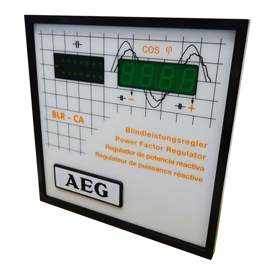
12. The digital indicator will show the system power factor.
f.e. i i i i 0,87 for lagging or c0.94 for leading load.
13. After the lock out time, with an inductive load on the system, if the relay is correctly connected, the + LED will start to flash.
14. If the installation is correctly connected, the relay will now switch successive steps, following the selected step time delay until the target
power factor is obtained. Each energized step will be indicated on the LED display 6. As each step switches in, so the digital display of
power factor will change. If the installation p.f. is above or below the target p.f., the "+" LED (Below Target) or "-" LED (Above Target) will
flash.
Advertisement

Related Manuals for AEG BLR-CA


Summary of Contents for AEG BLR-CA
- Page 1 Maschinenfabrik Reinhausen GmbH - AEG Compensation Systems | Sickingenstraße 71 | 10553 Berlin / Germany Phone : +49 30 34692-0 | Fax : +49 30 34692-255 | email: pqmb@reinhausen.com | Internet: http://www.reinhausen.com Operating & Commissioning Instructions BLR-CA As with all electrical equipment, the appropriate specifications governing electrical installation must be followed when Power Factor Correction Equipment is installed.
- Page 2 15. The BLR-CA does not require any adjustment of the responsiveness. Regulation does not follow a fixed switching program, different capacitor sizes can be used for the respective steps. The relay measures the output for each capacitor step in the form of "units of value"...
- Page 3 Function Switch (3) (Standard Version with 10 Switch Positions) 0 = Relay not in automatic function. All steps will be switched off after 20 secs. The digital display will show "OFF". 1 = Adjustment of pre-set target power factor within the range 0,70 lag ...1,0 ... 0,90 lead. by means of the +/- buttons. Target level is shown in the display.
- Page 4 Optional Setting Features A = Input of alternative target power factor level for low tariff operation. Setting range 0,70 lag ... 1,0 ... 0,90 lead. The required target level is adjusted in the display using the +/- buttons. In order to activate this feature a supply voltage of 150-240 V AC 50/60Hz must be applied to P and N.