Tascam DM-3200 Owner's Manual
Digital mixing console
Hide thumbs
Also See for DM-3200:
- Manual (36 pages) ,
- Release notes (26 pages) ,
- Software manual (8 pages)
Table of Contents
Advertisement
Quick Links
Advertisement
Table of Contents

Related Manuals for Tascam DM-3200


Summary of Contents for Tascam DM-3200
- Page 1 D001865710A Digital Mixing Console OWNER’S MANUAL...
- Page 2 Model number Serial number TASCAM DM-3200 Owner’s Manual For the consumers in Europe WARNING This is a Class A product. In a domestic environment, this product may cause radio interference in which case the user may be required to take adequate measures.
-
Page 3: Important Safety Instructions
The apparatus should be located close enough to the AC outlet so that you can easily grasp the power cord plug at any time. An apparatus with Class I construction shall be connected to an AC outlet with a protective grounding connection. TASCAM DM-3200 Owner’s Manual... -
Page 4: Table Of Contents
9, “Specifications” (page 102) ... 12 Notes and warnings ... 12 Special notes for touch-sensitive faders ... 13 Copyright, etc..13 The features of the DM-3200 ... 14 Control section ... 15 Monitoring section ... 15 Module & layer control section ... 15 Encoder section ... - Page 5 Compression/expansion ratio ...63 Attack time ...63 Release time ...63 Auto make-up ...64 Output gain ...64 Library jump buttons ...64 Preset dynamics library entries ...64 Compressor/expander library entries ...64 Gate library entries ...65 Trigger settings ...65 TASCAM DM-3200 Owner’s Manual Contents...
- Page 6 Information about a snapshot ... 80 6 – Effects Routing the effects ... 81 Setting up the effects ... 81 TASCAM effect parameters ... 82 TC Works effect parameters ... 83 Effect libraries ... 84 Preset TC Reverb effects ... 84 TASCAM DM-3200 Owner’s Manual...
- Page 7 Figure 1.1: Basic logical components of the DM-3200 ....... 10 Figure 1.1: Overview of the DM-3200 .
- Page 8 Figure 8.1: Adding external devices for control by the DM-3200 ....... . 93 Table 8.2: Control methods .
-
Page 9: Introduction
This section provides an overview of the features and facilities provided by the DM-3200. It also includes an overview of the operational procedures involved when using the unit. It is important to read this section to gain a basic understanding of the way that the DM-3200 works before proceeding with setting up and using the unit. -
Page 10: About The Dm-3200
Cascade 2-track in Figure 1.1: Basic logical components of the DM-3200 a. Note that cascade connections are not available on the first release of the DM-3200 software. TASCAM DM-3200 Owner’s Manual expansion card for direct high-speed bidirectional communication between a DAW and the DM-3200. -
Page 11: Channel Destinations
Lifting properly—When lifting, be sure of your footing and grip. Bend your legs to get close to the DM-3200, keeping your back straight, and then lift by straighten- ing your legs. Hold the unit close to your body. Avoid twisting or turning your body while lifting or carrying the DM-3200. -
Page 12: About The Manual
5, “Channel modules” (page 59) tion describes the modules which form the basic “building blocks” of the DM-3200. Most of the mix- ing work you do on the DM-3200 will use the func- tions described here. Notes and warnings We give hints and tips on using the DM-3200 in this way. -
Page 13: Special Notes For Touch-Sensitive Faders
1 – Introduction : Special notes for touch-sensitive faders Special notes for touch-sensitive faders The usual rules regarding precision electronic equip- ment naturally apply to the DM-3200. In addition, note the following that apply to the touch-sensitive faders: Copyright, etc. -
Page 14: The Features Of The Dm-3200
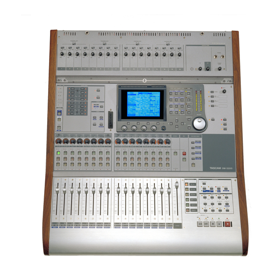
CF card slot Module and fader layer section TASCAM DM-3200 Owner’s Manual The front surface of the DM-3200 may seem a little intimidating at first, but it is actually remarkably sim- ple, considering the functionality built into the unit. -
Page 15: Control Section
1 – Introduction : The features of the DM-3200 Control section This section contains the screen, the dedicated func- tion keys, and the PODs, as well as the cursor keys and the data dial. Monitoring section This section contains the controls for the control room and studio monitoring and cueing controls, as well as the talkback microphone and slate controls. -
Page 16: Basic Operational Concepts
(latching). What’s on the screen? For almost all the screens displayed by the DM-3200, there are two common areas. The first is at the top, and we explain that area here (the second is the row of labels which identify the POD functions (described in “Special controls”... -
Page 17: Jumping To Commonly-Used Screens
Release all the keys. Next time you press that key (without the USER keys), the display shows the screen you set previously. TASCAM DM-3200 Owner’s Manual MODULE keys. keys are used to set With the keys (to the left of keys. -
Page 18: Fader Layers
These keys are located to the right of the master fader. When Special controls The DM-3200 incorporates a few controls that are not found on every digital mixer and which therefore may be a little unfamiliar. The PODs The DM-3200 has four encoder/key combinations (referred to as PODs) below the display. -
Page 19: Figure 2.4: Pod Knobs Used In A Multi-Control Screen
The POD knobs change values fairly coarsely, but be pressing and holding the SHIFT key (to the left of the unit), the POD knobs can be used for fine adjustment. This behavior can be changed (see “Encoder behavior” on page 23 below). TASCAM DM-3200 Owner’s Manual ENTER... -
Page 20: Encoders
There are three settings for each key, depending on whether the key is pressed alone, or with the SHIFT the left of the DM-3200, above module 1). Key pressed alone Pan position in stereo mode(L-R pan in surround) for the selected... -
Page 21: Snd Aux 1-2
Centered left Figure 2.11: Encoders in pan mode even when the line of sight to the center indicator is blocked by the encoder knob. TASCAM DM-3200 Owner’s Manual The 16 encoders control the levels of the Encoders 1 CTRL ENCODER... -
Page 22: Eq Settings
(minimum band- width) Figure 2.14: Encoders in frequency Q adjustment mode TASCAM DM-3200 Owner’s Manual The first encoder in each band is used to control the gain, the indicators are used as below. “Half-steps” are indicated by dimmed indicators. Note also the... -
Page 23: Module Levels And Aux Sends
(at the as alternatives for the unshifted mode. Figure 2.17: ENCODER OPERATION menu item Press ENTER OPTION TASCAM DM-3200 Owner’s Manual Above nominal level key exchanges the func- FLIP OPTION ENCODER OPERATION item, which allows... -
Page 24: Cf Cards
(see “About projects and libraries” on FORMAT page 26) or the library management screens (see “Library management” on page 30). • The DM-3200 system date and time can be set here (see “Setting the date and time” on page 27). to con- ENTER... -
Page 25: Shutting Down The Dm-3200
2 – Basic operational concepts : Shutting down the DM-3200 Shutting down the DM-3200 IMPORTANT CAUTION!!! Data associated with projects (automation, library entries, etc.) is not auto- matically stored on the card. If you turn off the DM- 3200 without having shut down the DM-3200 properly,... -
Page 26: About Projects And Libraries
Each of these banks contains 128 “slots” to hold set- tings (numbered from In addition, the preset bank, stored in the DM-3200’s memory, is available for recall of presets to be used as starting points for user settings. The effect library has access to two preset banks. -
Page 27: Setting The Date And Time
2 – Basic operational concepts : About projects and libraries Setting the date and time To set the date on the DM-3200, follow the steps below: 1 Enter the screen, and jump to the UTILITY page: SYSTEM Figure 2.22: Setting the date and time... -
Page 28: Managing Projects
ENTER A popup message briefly appears while loading the project, and also when the load process is completed. TASCAM DM-3200 Owner’s Manual NOTE The default internal project when loaded does not allow the storage of automation, or the storage or recall of library entries—its main function is to serve as... -
Page 29: Saving Project Data
STORE AS button to bring up the naming panel (see “Naming library entries” on page 32), allowing the current project settings to be stored under a different name (similar to Save As... on many computer programs). TASCAM DM-3200 Owner’s Manual... -
Page 30: Library Management
2 – Basic operational concepts : Library management Library management The following libraries are available within each project on the DM-3200 for storing and recalling commonly-used settings: • Snapshots (scene memories) • EQ settings • Compressor/expander settings • Gate settings •... -
Page 31: Viewing Library Entries
Use the on-screen buttons at the bottom of the left side of the screen to select the bank to be used as a target. Use the POD 2 encoder to scroll through the list of entries in the selected bank. TASCAM DM-3200 Owner’s Manual DELETE . A popup... -
Page 32: Source Parameters
When the characters of the title have been entered, press the on-screen enter the name and store the library entry (or project). POD 3 ( process. SETUP parameters relating to the operation of the DM-3200, key. while the SOLO cerned with solo operations. screen appears. -
Page 33: Upper Bar Display
9-pin serial port ( RS-422 IN TC ), and any other timecode received. The TASCAM Mixer Companion software can also dis- play the timecode in a window on a personal computer. LOCATE DISPLAY mode This parameter deter- mines how a location entry will be shown on the dis-... -
Page 34: Preferences
For example, if this option is active, and lit with fader layer 1-16 active, fader layer 17-32 is TASCAM DM-3200 Owner’s Manual STATUS/OL touched. This provides a useful check for the sensi- tivity of the faders. -
Page 35: Buss Link/Buss Pan Are Linked
SOLO The solo modes on the DM-3200 can be set up in a number of different ways using this screen: Figure 2.33: SOLO options MODE SELECT... -
Page 36: Utilities
There is also a system update facility. See the TMCompanion software and its documentation for full details of how to update the DM-3200. Naturally, it is not possible to select both in the same box, though it is possible to select... -
Page 37: Switch Utility
(the DM- 3200 expects a push-to-make momentary switch, but by flipping the polarity to switch can be used instead). . See “Remote TASCAM DM-3200 Owner’s Manual The following functions dupli- SHIFT duplicates the use of Automation KEEP... -
Page 38: Figure 3.1: Overview Of Rear Panel Features
This section describes how the DM-3200 connects to other equipment in your studio. Since the DM-3200 is extremely “soft” in terms of the internal routing and patching, it is unlikely that you will need to spend a lot of time connecting and disconnecting equipment once you have your setup in place. -
Page 39: Analog Connections
1 ground, pin 2 hot and pin 3 cold. The TSR 1/4" jacks are tip hot, sleeve ground, ring cold (this applies to all balanced 1/4" jacks on the DM-3200). Both the XLR mic connection and the 1/4" jack con- nection can be made at one time, but it is only possi- ble to accept input signals from one source at a time. -
Page 40: Analog Outputs
CASCADE This is a special connector, used only to connect another DM-3200 unit to extend the capabil- ities of the DM-3200. This facility is not available in the first release of the software. TASCAM DM-3200 User’s Manual ASSIGNABLE SENDS These are balanced 1/4"... -
Page 41: Digital I/O Setup
In the event of bad digi- tal audio data being received (out of range, or cor- rupt, etc.), the DM-3200 will usually mute the input to prevent possible damage to monitoring equipment. However, this automatic muting can be turned off with this checkbox. -
Page 42: Figure 3.4: If-An/Dm (At Left) And If-Ae/Dm (At Right)
This MIDI functionality can be used to provide either open or closed MMC loop control of remote devices, as well as allowing the DM-3200 to control other devices through its faders and encoders. See “MIDI” on page 91 for details. -
Page 43: To Meter
More than one such word sync source can cause serious problems, including possible damage to monitoring equipment. The DM-3200 can act as a word sync master or slave (set up in software—see “Clock setting” on page 44). The switch allows the... -
Page 44: Clock Setting
Remember that the DM-3200 can act as a clock source or clock master, but there must be only one master clock source in your studio setup. -
Page 45: Changing The Clock
42) can be inverted using the on-screen phase controls. OUT SPEED clock transmitted from the either the high-speed (88.2/96) clock or the corre- sponding normal speed (44.1/48) clock. TASCAM DM-3200 User’s Manual High-speed 96K/88.2K 96K/88.2K Manual setup, 96K/88.2K 96K/88.2K (note that this is dual-line input... -
Page 46: Figure 4.1: Module Facilities On The Dm-3200
The DM-3200 is equipped with two types of mixer channel modules, with the first 32 fully equipped with EQ and full dynamics processing, and modules 33 through 48 being more similar to the basic return channels on a traditional recording mixer. -
Page 47: Routing & Assignment Routing
INPUT from a list composed of (mainly) the physical inputs of the DM-3200, and route them to input destinations (channels and dynamics triggers). Figure 4.2: Routing inputs 1 Select the source group with the POD 4 encoder. -
Page 48: Batch Routing
1 through 32, as these are the only ones for which the input and return sources may be selected. TASCAM DM-3200 User’s Manual 1 Use the dial to select the destination field (the left field) and confirm with... -
Page 49: Output Routing
Output routing The output routing screen allows you to tie the logi- cal outputs from the different parts of the DM-3200 to the physical output ports. Figure 4.3: Routing outputs There are two such screens, one dedicated to the built-in outputs of the DM-3200, and the other dedi- cated to the outputs provided by any optional cards fitted in the slots. -
Page 50: Insert Patching
The software inserts are available to many more internal modules. Although these insert loops may exit from the DM-3200 in either the analog or digital domain, they may also remain completely within the unit, using internal “patch” connections. These “soft” inserts allow 16 different input and out- put pairs to be defined as inserts at definable points in the DM-3200 signal path. -
Page 51: Channel-To-Buss Assignment
Figure 4.5: Assignment keys busses and the aux sends to the appropriate destina- tions, in an easy graphical solution. These screens Figure 4.6: Buss assignment screen (linked TASCAM DM-3200 User’s Manual busses) -
Page 52: Pan Switch
However, when this switch is not set, the buss pairs can be split for individual assignment. TASCAM DM-3200 User’s Manual • Pressing and holding the pressing one of the split or join function on a buss pair, allowing busses to be individually assigned when split. -
Page 53: Surround Assignments
(see “Aux and buss setup” on page 68). See also “BUSS PAN Follows ST PAN” on page 34 for- details of how buss and stereo panning are linked. TASCAM DM-3200 User’s Manual Assignments from The POD 1 and POD 2... -
Page 54: Monitoring
4 – Routing & assignment : Monitoring Monitoring The DM-3200 provides comprehensive monitoring and metering facilities allowing both control room and studio cue mixes to be produced. Figure 4.9: Monitoring and metering controls Selecting the CR source The four dedicated keys and indicators to the right of... -
Page 55: Studio Cue Source
Since there are several options in the routing, etc. that only affect the aux 1–2 sends, we suggest that you use these as a separate studio cue feed. The volume of the studio cue is adjusted from this screen using the POD 4 encoder. TASCAM DM-3200 User’s Manual vol-... -
Page 56: Figure 4.11: Monitor Oscillator And Communication
Oscillator and noise generator In order to help with signal tracing, the setting of SPLs, etc., the DM-3200 provides an internal tone/ noise generator. The POD 1 switch turns the generator on and off. -
Page 57: Figure 4.12: Metering Screen (1St 24 Channel Module Meters)
If the optional meter bridge is fitted, the settings made here apply to the meter displays on the meter bridge, as well as to the on-screen meter displays. The TASCAM Mixer Companion software provides a software “meter bridge”. TASCAM DM-3200 User’s Manual... -
Page 58: Soloing
MONITOR or is lit when one or more channels are soloed, to indicate that solo mode is active. TASCAM DM-3200 User’s Manual PFL soloing flashes the indicator slowly, AFL flashes it fast, and the inplace solo mode lights it steadily. -
Page 59: General Principles
The channel modules are the “heart” of the DM-3200, corresponding to the channel strips on an analog con- sole. Because they are used so often, and settings have to be made frequently, there are a number of ways of viewing and making the settings for these modules, as explained in this section. -
Page 60: Input And Return Display
COMP expander to be turned on and off for comparison. TASCAM DM-3200 User’s Manual Compressor/expander point button this button to change the point at which the compres- sor/limiter is inserted in the channel between a pre-... -
Page 61: Aux1-2 Button
POD 3 to set the level, and POD 4 to select the target, with the to confirm the setting. TASCAM DM-3200 User’s Manual Display, but do button when done. A popup ) or... -
Page 62: Figure 5.5: Unlinked Dynamics Screen (Channels 1 Through 32)
5 – Channel modules : Dynamics processors Dynamics processors This section covers the use of the DM-3200’s built-in compressor/expanders and gates. Compressor/expander dynamics processors are avail- able in all modules except channel modules 33 through 48. Gates are available in channels 1 thorough 32 (input only). -
Page 63: Gates (Input Channels 1–32)
RATIO ), con- 300 ms to 500 ms 500 ms to 1.00 s 1.00 s to 3.00 s 3.00 s to 5.00 s TASCAM DM-3200 User’s Manual HOLD , controlled by the POD 3 990ms , controlled by the 50ms... -
Page 64: Auto Make-Up
Expander1 Expander2 Slow Attack E Guitar Clean1 Table 5.7: Compressor/Expander preset library entries TASCAM DM-3200 User’s Manual Library jump buttons screen library jump buttons on channels 1 through 32 (gate and compressor/expander). Other modules only have the compressor/expander jump keys. -
Page 65: Gate Library Entries
E Gt Distortion E Gt Heavy Dist. Table 5.8: Gate/Expander preset library entries Trigger settings As mentioned earlier, the DM-3200 can have sources assigned to triggers (up to eight), allowing dynamics processors to be triggered by a wide range of input signals. -
Page 66: Encoders And Eq
5 – Channel modules : EQ The four-band EQ provided on the first 32 channel modules of the DM-3200 allows precise sound shap- ing, combined with flexibility, and repeatability, thanks to the library store and recall facilities. To view the EQ settings for a module, press the key until the EQ page is shown. -
Page 67: Eq Library
EQ library You can recall and use preset EQ settings from the DM-3200 library, as well as storing your own set- tings to user areas of the library for further use (see “Library management” on page 30 for details of how library functions work with the DM-3200). -
Page 68: Aux And Buss Setup
Use the cursor keys and key to set the pre/ ENTER post aux send position. TASCAM DM-3200 User’s Manual NOTE Aux 1-2 have an extra option here. In addition to being able to select the pre- and post-fader aux send position, channels 1 through 32 can also use the “return”... -
Page 69: Source Selection
Current Screen” on page 34) the encoders will auto- matically change to the aux send and pan/balance mode when the aux screens are selected. TASCAM DM-3200 User’s Manual ) or from the aux sends to the chan- ). Use the on-screen... -
Page 70: Module Setup
GATE switching Use POD 2 on the first row as a rotary switch to turn the gate for the module on or off. TASCAM DM-3200 User’s Manual AUX 1-2 SOURCE SETUP It is suggested that the aux 1 and 2 sends are used as studio foldback (cue) sends. -
Page 71: Digital Trim
) to bring up the trim screen. Figure 5.19: Digital trim setting Use the cursor keys to select blocks of four channels and the PODs to set the values. TASCAM DM-3200 User’s Manual button to link the pan- GANG DIGI. TRIM/DELAY... -
Page 72: Delay
• Gate settings • Compressor settings and insertion point • EQ settings • Aux send levels/pan-balance setting/pickoff point TASCAM DM-3200 User’s Manual POD 3 and 4 and the key work in the same ENTER way as they do for the digital trim. -
Page 73: Balance
See “Dynamics proces- sors” on page 62 for details of how this works. Use the LINK/GRP key to bring up the links screens: Figure 5.24: Mute grouping TASCAM DM-3200 User’s Manual ST LINK screen brought up key. keys to move the... -
Page 74: Clearing Groups
Fader groups These work in the same way as for mute groups. Figure 5.27: Fader grouping TASCAM DM-3200 User’s Manual Grouping groups keys to group of another group, using the matrix at the bot- tom of the screen. -
Page 75: Surround Operations
• There are two surround matrices. These can have keys. ASSIGN pan mode turned on and off independently for each channel ( SHIFT matrix, and second). TASCAM DM-3200 User’s Manual When a surround mode is LCRS — — — — —... -
Page 76: Surround Panning
• Use the POD 3 encoder to select either sur- round matrix 1 or 2. TASCAM DM-3200 User’s Manual The difference between these is that when pan mode is off, the channels can be assigned individually to the surround channels (following Table 5.29, Buss assignments in surround mode). -
Page 77: Pattern Panning
Jump keys the numbered nal to the appropriate point in the sound stage ( front left, is front center, ENTER TASCAM DM-3200 User’s Manual In the second row of POD con- (where the sig- CIRCLE SQUARE SLANT s (diagonally across the... -
Page 78: Pan Mode Off
The amount of signal sent by each channel to the LFE output can be set in the LFE LEVEL Figure 5.35: LFE level TASCAM DM-3200 User’s Manual matrix selection and the individual speaker selection on-screen buttons. Figure 5.34: Surround screen (pan mode off) -
Page 79: Snapshots
EQ settings and routing). • Use the POD 3 switch or the cursor at the on-screen button to recall the currently RECALL selected library entry. A popup message appears briefly. TASCAM DM-3200 User’s Manual... -
Page 80: Storing Snapshots
When the library screen is visible, pressing the POD 4 switch brings up a popup information panel about the snapshot whose library entry is highlighted in the right-hand list. TASCAM DM-3200 User’s Manual • On the left side of the screen, use the wheel ENTER shot. -
Page 81: Effects
The DM-3200 incorporates two internal effects: a TASCAM multi-purpose effect and a TC Works reverb. This section discusses the setup and use of these effects. Routing the effects As explained in “Routing” on page 47, internal effect inputs and outputs are treated as sources and destina- tions for routing. -
Page 82: Tascam Effect Parameters
Figure 6.4: Common effect parameters (Row 1) TASCAM effect parameters The TASCAM effects (chorus, de-esser, delay, dis- tortion, exciter, flanger, guitar compressor, phaser, pitch shifter, soft compressor) use the third row of PODs as follows (display labels are shown in paren-... -
Page 83: Tc Works Effect Parameters
Attack time (ATTACK) 0.05 s – 5.00 s — Table 6.5: TASCAM effect parameters The top row is the same as for the TASCAM effect settings, and the other PODs are used as follows: POD 3 HIGH CUT FILTER Tail balance (TAIL) High cut filter frequency <50 –... -
Page 84: Effect Libraries
FX - Dry After Taste FX - Icy Shower FX - Lost in Space FX - Neighbor (Hallway) FX - Neighbor 2 (Floor) TASCAM DM-3200 User’s Manual POD 3 Reverb tail level (REVLEV) Initial reflection pre-delay time (IR DLY) Off, –140 dB – 0 dB 0 ms –... - Page 85 Hall-Big Warm Hall-Cathdral12s Hall-Cathedral7s Hall-Church Hall-Dome Hall-Huge Clear Hall-Huge Warm Hall-LastRowStdm Hall-Lush Ballad Hall-Med.Bright Hall-MediumClear Hall-Medium Warm Hall-OutsideStdm Hall-SmallBright Hall-Small Clear Hall-Small Warm Hall-Stage Hall-Warm Vocal Drum-Boom Room Drum-Drum Booth Table 6.7: Preset TC Reverb effects TASCAM DM-3200 User’s Manual...
- Page 86 Room - Small Yet Big w/Pre Room - Stage Room - Vocal Booth Room - Vocal Dry Room - Vocal Room Room - Vocal Room 2 TASCAM DM-3200 User’s Manual LCD indication Drum-HugeLowTubu Drum-Low Tubular Drum-Snare Hall Drum-Snare Room Drum-SubtleKick...
-
Page 87: Preset Tascam Effects
Preset TASCAM effects The preset TASCAM effects available from preset bank 2 are: Preset Effect type Title Guitar Compressor Guitar Comp. Classic Comp. Sustain Fat Comp. Deep Comp. Rhythm Comp. Fast Attack Slow Attack Slap Comp. Percussive Distortion Distortion Over Drive... - Page 88 Rhythm Phaser 2 Rhythm Phaser 2 Fast rhythm phaser Vocal Phaser 1 Vocal Phaser 2 Drum Phaser Fusion Phaser Vibrato Phaser Wah Phaser TASCAM DM-3200 User’s Manual LCD indication Comments Trebly Driving sound with a lot of treble Solo "Humbucker” solo sound Crunch “Crunch”...
- Page 89 A chorus sound with a strong tremolo. Ensemble 3 Another kind of ensemble sound Clean Chorus 1 A light chorus sound Clean Chorus 2 Use this clean sound with vocals Clean Chorus 3 A vibrato-type chorus effect Table 6.8: TASCAM effects TASCAM DM-3200 User’s Manual...
- Page 90 Jet Flanger 1 Jet Flanger 2 Sweet Flanger Flanger Echo Tremolo Flange Deep Flanger Metallic Tone TASCAM DM-3200 User’s Manual LCD indication Comments Pitch shifter Octave doubler Ensemble 1 A repeat setting to give an ensemble effect Ensemble 2 A short repeat provides a “coming and going” effect...
-
Page 91: Midi
As well as the MIDI ports, the DM-3200 can pass MIDI to and from a PC connected using the USB connec- tion (as well as through a FireWire connection if an optional FireWire interface card is fitted). This section explains some of the ways in which the card is used. -
Page 92: Program Change Messages And The Dm-3200
7 – MIDI : Program Change messages and the DM-3200 Program Change messages and the DM-3200 The DM-3200 can receive Program Change mes- sages to recall snapshot settings, or settings from either of the two effect libraries. Figure 7.2: MIDI Program Change screen... -
Page 93: Remote Operation Selecting Devices For Transport Control
The DM-3200 is capable of acting as a remote control unit for a wide variety of external devices. The exact functionality of the machine control depends, of course, on the device to be controlled. The device control is carried out through the MIDI... -
Page 94: Deleting Devices From The List
(that is, commands are sent from the DM- 3200 to the device, but no information is transmitted back from the device to the DM-3200 along the same channel—information is transmitted from the other device through a different channel, such as timecode or MIDI). -
Page 95: Chase
This allows the selection of the key above the stereo fader + the channel keys) on the DM-3200 which arm the tracks on the remote external device. • symbol. If a... -
Page 96: To Use A Transport Mapping
10). If there are IDs associated with the devices, these are also shown. The DM-3200’s transport control keys will now con- trol the device selected in that map and the other mapping features will also be enabled. A popup shows the currently-recalled memory (or a message if no mapping has been recalled). -
Page 97: Machine Control Setup
However, if the key is pressed while the PLAY Play Command Type Use this option to make the play commands from the DM-3200’s MIDI Machine Control compatible with the unit being controlled. key. This allows the setting of various machine control REMOTE parameters. -
Page 98: Record Command Type
8 – Remote operation : Machine control setup Record Command Type Use this option to make the record commands from the DM-3200’s MIDI Machine Control compatible with the unit being controlled. Locate Preroll Move the cursor to the numeric field, which shows the pre-roll time when a location point is reached (displayed in minutes and seconds). -
Page 99: Location Memories
Location memories The DM-3200 allows the storage and recall of up to ten location memories, allowing easy location of the controlled devices to predetermined cue points. Selecting the location point display As explained in “LOCATE DISPLAY mode” on page 33, the... -
Page 100: Viewing A List Of Location Memories
MACHINE CONTROL section. While the repeat loop is in progress, the indicator flashes while the playback position is outside the TASCAM DM-3200 User’s Manual • The location memory source (timecode or MTC) is shown, along with the value of each location memory. -
Page 101: Auto Punch Operations
Playback continues until the in point, when the unit drops into record RECORD DM-3200 punches out. Repeat until you’re happy with the take. 3 To review the punch recording, press the key so that the indicator lights steadily. -
Page 102: Specifications
9 – Specifications This section provides technical and reference information about the DM-3200, together with a list of messages you may see on the display of the DM-3200 and instructions about how to respond to them. Analog audio I/O All specifications are given with the factory reference level of –16 dBFS. -
Page 103: Digital Audio I/O
9-pin female D-sub connector (non-metric lock screws) wired to RS-422 standards 9-pin female D-sub connector (non-metric lock screws) wired for GPI control Pin 1=GP11, Pin 2=GPI2, Pin 3=GPI3, Pin 4=GPI4, Pin 5=GND, Pin 6=GPI5, Pin 7=GPI6, Pin 8=GPI7, Pin 9=GP18 TASCAM DM-3200 Owner’s Manual... -
Page 104: Equalization
Maximum overall dimensions (w x d x h) including rest 700 x 824 x 230 (mm) 27.6 x 32.4 x 9.1 (in) Weight Voltage requirements Power consumption Supplied accessories TASCAM DM-3200 Owner’s Manual ±18 dB, 0.5 dB resolution 31 Hz to 19 kHz 0.27 to 8.65 Hi-shelving, Peak, LPF ±18 dB, 0.5 dB resolution... -
Page 105: Dimensional Drawing
Dimensional drawing Messages and troubleshooting This provides an alphabetical list of the messages that you may see on the DM-3200, which provide information on the operation that you are performing. Not all of these messages are error messages. “Information” messages, i.e. those which pop up briefly and provide information about a change in status, etc., are marked with a . - Page 106 Copying the channel fader levels to the Aux 1-2 levels. The internal battery is defective, or has lost charge, so data can’t be stored. Contact TASCAM service or your distributor for a replacement battery. An attempt has been made to make an invalid fader group (“Fader groups” on page 74) There is a limit of 128 projects that can be created on one CF card.
- Page 107 Automation data can’t be stored. Reinsert the card or retry with another card. An attempt to shut down the DM-3200 has failed, because a CF card is not available. Reinsert the card or retry with another card.
- Page 108 Confirm TRA Auto Detect? Press ENTER to confirm, or a cursor key to cancel. TASCAM DM-3200 Owner’s Manual Meaning Shown when the currently selected fader grouping is to be cleared. Results of performing a word sync check.
- Page 109 Popup message on completion of copy operation. Confirming creation of a project. Warning not to remove CF card during project completion. Notice to restart the DM-3200 following a change of reinitialization and sampling frequency Notice to restart the DM-3200 following a change of sampling frequency.
- Page 110 A CF card format operation has failed. Warning not to remove power while card is being formatted. Notice to restart the DM-3200 following a change of sampling frequency. Information about a library preset entry (gate). A library entry has been recalled (gate).
- Page 111 Reminder that stored names and memos must be 16 characters or less in length. An attempt has been made to copy data, without a parameter’s checkbox being selected. A copy is being carried out. Table 9.2: Popup messages TASCAM DM-3200 Owner’s Manual...
- Page 112 OK to Overwrite xxx Library BANK a-bbb from Cgy? Press ENTER to confirm, or a cursor key to cancel. TASCAM DM-3200 Owner’s Manual Meaning Conformation that a library bank (EQ, snapshot, etc.) can be copied from one project to another.
- Page 113 On power-up — a shutdown was not performed properly. Should data changed after the project was last stored be loaded? Detail information popup for digital audio output Detail information popup for digital audio I/O (AES card) Table 9.2: Popup messages TASCAM DM-3200 Owner’s Manual...
- Page 114 Stored to EFFECT Library BANK a-bbb Stored to xxxx Library BANK a-bbb from CHx. TASCAM DM-3200 Owner’s Manual Meaning No signal received at a digital input when detail is requested Detail information popup for digital audio I/O (TDIF) Digital audio data error from AES card (non-audio data).
- Page 115 Confirmation that the current project should be stored on the card (it is not already there). Automation and library data will not be stored. The shutdown process is now complete, and the power can be turned off, or the DM-3200 can be rebooted. Table 9.2: Popup messages TASCAM DM-3200 Owner’s Manual...
-
Page 116: Block Diagram
9 – Specifications : Block diagram Block diagram Figure 9.3: Block diagram TASCAM DM-3200 Owner’s Manual... -
Page 117: Level Diagram
9 – Specifications : Level diagram Level diagram Figure 9.4: Level diagram TASCAM DM-3200 Owner’s Manual... - Page 118 Notes TASCAM DM-3200 Owner’s Manual...
- Page 119 Notes TASCAM DM-3200 Owner’s Manual...
- Page 120 DM-3200 TEAC CORPORATION Phone: +81-422-52-5082 3-7-3, Nakacho, Musashino-shi, Tokyo 180-8550, Japan TEAC AMERICA, INC. Phone: +1-323-726-0303 7733 Telegraph Road, Montebello, California 90640 TEAC CANADA LTD. Phone: +1905-890-8008 Facsimile: +1905-890-9888 5939 Wallace Street, Mississauga, Ontario L4Z 1Z8, Canada TEAC MEXICO, S.A. De C.V Phone: +52-555-581-5500 Campesinos No.