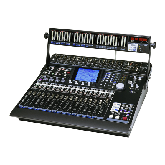
Tascam DM-24 Owner's Manual
Digital mixing console
Hide thumbs
Also See for DM-24:
- Service manual (90 pages) ,
- Automation manual (36 pages) ,
- Effects manual (32 pages)
Table of Contents
Advertisement
Quick Links
DM-24
Digital Mixing Console
Professional
Ü
The lightning flash with arrowhead symbol, within an equilateral triangle, is intended to alert
ÿ
the user to the presence of uninsulated "dangerous voltage" within the product's enclosure
that may be of sufficient magnitude to constitute a risk of electric shock to persons.
The exclamation point within an equilateral triangle is intended to alert the user to the pres-
Ÿ
ence of important operating and maintenance (servicing) instructions in the literature
accompanying the appliance.
This appliance has a serial number
located on the rear panel. Please record
the model number and serial number
and retain them for your records.
Model number
Serial number
OWNER'S MANUAL
CAUTION: TO REDUCE THE RISK OF ELECTRIC SHOCK, DO NOT
REMOVE COVER (OR BACK). NO USER-SERVICEABLE PARTS INSIDE.
REFER SERVICING TO QUALIFIED SERVICE PERSONNEL.
WARNING: TO PREVENT FIRE OR SHOCK
HAZARD, DO NOT EXPOSE THIS
APPLIANCE TO RAIN OR MOISTURE.
9101439701
Advertisement
Table of Contents

Related Manuals for Tascam DM-24


Summary of Contents for Tascam DM-24
- Page 1 DM-24 Digital Mixing Console Professional Ü The lightning flash with arrowhead symbol, within an equilateral triangle, is intended to alert ÿ the user to the presence of uninsulated “dangerous voltage” within the product’s enclosure that may be of sufficient magnitude to constitute a risk of electric shock to persons.
- Page 2 When replacing the fuse only a correctly rated approved type should be used and be sure to re-fit the fuse cover. IF IN DOUBT — CONSULT A COMPETENT ELECTRICIAN. TASCAM DM-24 For U.S.A TO THE USER This equipment has been tested and found to comply with the limits for a Class A digital device, pursuant to Part 15 of the FCC Rules.
-
Page 3: Important Safety Instructions
24) Heat — The product should be situated away from heat sources such as radiators, heat registers, stoves, or other products (including amplifiers) that produce heat. TASCAM DM-24 ANTENNA LEAD IN WIRE... -
Page 4: Table Of Contents
Other digital input parameters ... 26 Digital output ... 26 Multi I/O settings ... 26 Stereo out setup ... 26 SLOT screen ...27 4 – Parts of the DM-24 Top surface ...28 Analog module inputs ...29 Other analog I/O ...29 Module control section ...30 Library section ...30... - Page 5 Assigning processors to master channels ... 65 Dynamics diagram ... 66 Gates/expanders ... 66 Gate ... 66 Threshold ...66 Range ...66 Hysteresis ...66 Gate attack time ...66 Gate hold time ...66 Gate decay time ...66 Expander ... 66 Threshold ...66 Ratio ...66 TASCAM DM-24...
- Page 6 MIDI controllers ...93 MIDI faders ...93 12 – MIDI Bulk dumps ...95 Bulk transfer of data from the DM-24 ...95 Bulk transfer of data to the DM-24 ...96 Updating the system software ...96 Control Change messages to and from the DM-24 ...96 MIDI Implementation Chart ...98...
- Page 7 Analog audio I/O ... 124 Digital audio I/O ... 125 Miscellaneous I/O connections ... 125 Equalization ... 126 System performance ... 126 Physical characteristics ... 126 Dimensional drawing ... 127 Messages and troubleshooting ... 127 Block diagram (normal sampling TASCAM DM-24...
-
Page 8: Introduction
If you learn a little about the key features and princi- ples of operation now, before you start to use the DM-24 it will save you time and trouble later on. • the capability of acting as a remote controller for a... -
Page 9: Supplied Accessories
If any of these items is missing, contact your TAS- CAM distributor. Retain the box and other packing material that came with the DM-24 in case you need to transport it in the future. • The names of any physical keys, connectors and controls of other devices are given in the following typeface: REMOTE IN. - Page 10 MIDI timecode synchronization facilities. This section provides a guide to these facilities, as well as the way that the DM-24 can act as a location memory and recall unit for these external devices. 12 – “MIDI” on page 95 :...
-
Page 11: Word Clock Issues
If the DM-24 is to be a word clock slave in your system, it can accept word clocks from the following sources: •... -
Page 12: User Interface
However, since the number of parameters and fea- tures available on the DM-24 is more than a single screen can display, four screens are available for each module, accessed through the soft keys (“Soft keys”... -
Page 13: Pods
PODs to make changes to the module’s parameters. See below for details. PODs The DM-24 features four rotary controls immedi- ately below the screen, called PODs. These are used as “soft” controls to adjust parame- ters; that is, they have no fixed assignment to control... -
Page 14: Other Ways Of Changing Values
The status of the fader control setting is memorized between screens (and even when the DM-24 is turned off and on again). It is therefore possible for the fad- ers to move when the screen is changed. -
Page 15: Soft Keys
In this mode none of the encoder indica- tors (to the left of the encoders) is lit, and the band controlled is determined by the appropriate key. EQUALIZER TASCAM DM-24 Reference Manual MONITOR... -
Page 16: Encoders Used As Eq Gain Controls
The Q of an EQ band refers to the width of the filter when it is in notch or peak mode (but not in shelf or TASCAM DM-24 Reference Manual See the appropriate section on module operations (“Module operations” on page 49) for full details of the parameters controlled here. -
Page 17: Encoders Used As Pan Controls
LEDs above the unity point light in sequence (inter- mediate positions shown by dimmed LEDs), with the LEDs below the unity point being dimmed. The dia- gram here shows a setting just below maximum (9.6dB): = on = dimmed = off TASCAM DM-24 Reference Manual... -
Page 18: Fader Layers
Machine control keys As well as the keys controlling the DM-24 functions, there are also dedicated keys to control external devices connected to the DM-24. Among these keys there are dedicated transport keys... -
Page 19: Automation Status
The operation of the automation facilities is explained in a separate manual. When the automation engine is enabled, the word AUTO appears at the top of the screen, together with any automation mode currently enabled. TASCAM DM-24 Reference Manual key is used in automation... -
Page 20: System-Wide Options
3 – System-wide options The DM-24 provides a number of options which con- trol the overall functionality of the console. These are accessed through the OPTION screens. Within these screens, you can (in the • Set up various interface preferences •... -
Page 21: Fader Sensitivity
This parameter allows you to specify the sensitivity of the faders, as used in the automation process. The DM-24 touch sensing capabilities are dependent on the ambient humidity and environment. Depend- ing on these factors, it may sometimes happen that... -
Page 22: Meter Follows Sel Key
) is pressed, the box cursor surrounding the active on-screen controls will move to highlight the active band. SOLO The solo modes on the DM-24 can be set up in a number of different ways using this screen: TASCAM DM-24 Reference Manual FLASH Info. -
Page 23: Solo Type
(use to make the setting). ENTER at the top right of the DM-24 display (above the time- code value). If timecode is selected as the timing source on the DTRS unit, of the display. -
Page 24: Midi In Mtc
MIDI IN MTC This refers to any MIDI Timecode received at the jack. If this option is selected, MIDI IN is shown on the top right of the DM-24 display. INT. This refers to the DM-24’s own internal (MIDI Timecode) generator. NOTE The internal timecode generator is not functional in this release of the DM-24 software. -
Page 25: High Sampling Frequency
ENTER When the DM-24 changes to high sampling fre- quency, a popup message is shown on screen, telling you to turn off the DM-24 and turn it on again, to enter high sampling frequency mode. NOTE Remember to turn down the monitor value, etc. to avoid “thumps”... -
Page 26: Out Of Range Clock Signals
(44.1 k or 48 k). This is shown as on the display. However, if the DM-24 is in high sampling frequency mode, these inputs may be used for high sampling frequency inputs. There are two ways in which they can be used for high sampling frequency;... -
Page 27: Slot Screen
SLOT screen On the slot screen, the different optional interface cards that can be fitted to the DM-24 are automati- cally detected and the options can be set. These are described separately in “Options” on page 118. 3 – System-wide options—DIGITAL screens If slot cards have been fitted, they are shown on this screen, as in the example below. -
Page 28: Parts Of The Dm-24 Top Surface
Module control Module faders and selection, etc. TASCAM DM-24 Reference Manual This section is not a complete guide to the functions of the DM-24—treat it more as a “road-map” than a guidebook. Parameter control Transport and automation control Other analog I/O... -
Page 29: Analog Module Inputs
6 MONITOR OUTPUTS [CR (BAL)] 1/4” balanced analog outputs are used to provide monitoring signals to the control room as selected 4 – Parts of the DM-24—Top surface NOTE There is no switch to allow a choice between the MIC and the LINE inputs. -
Page 30: Module Control Section
I EXT CLOCK indicator lit, the DM-24 is referenced to externals word sync. If unlit, the DM-24 is acting as the master word sync source for the system. If flashing, the clock source is not connected, or is not otherwise available for use by the DM-24. -
Page 31: Parameter Control Section
Z JOG/DATA dial on-screen parameter values, etc. When the DM-24 is controlling the transport of a remote device, it may MIDI/MC be used to perform a jog function. -
Page 32: Monitoring Section
4 – Parts of the DM-24—Top surface a ENTER key Use this key to confirm entries and to answer “yes” to questions (the cursor keys are usually used to cancel or answer “no”). Monitoring section This section is used to control what is heard from the control room and the studio monitoring systems. -
Page 33: Module Faders And Selection, Etc
U I O This controls in this section provide remote control facilities for recording devices, etc. attached to the DM-24. 4 – Parts of the DM-24—Top surface functions. The indicators light to show which module has been selected. o MUTE keys tors, show the muting status of the modules. -
Page 34: Rear Panel
These keys have other functions, as selected by the key ( 2ND F Rear panel The rear panel of the DM-24 houses the digital audio and control connections. NOTE Only use TASCAM-supplied and TASCAM-approved cables when making digital audio and control connec- tions to the DM-24. - Page 35 24. Use only the provided power cord to connect the DM-24 to the AC supply, ensuring that the voltage of the supply matches the voltage requirements as given on the rear panel of the DM-24. If you are in any doubt, consult a qualified electrician. NOTE...
-
Page 36: Setting Up The I/O
5 – Setting up the I/O Because the DM-24 is a “soft” digital mixing con- sole, there are few of the hard-wired assignments that you find on an analog console. In addition, the DM-24 includes an internal patchbay, which allows routing and splitting of signals within... -
Page 37: Output Signals
Output signals The following are the signals output from the DM-24 (excluding the monitoring signals): Eight output busses These busses are typically routed to the built-in multi-track outputs (TDIF and ADAT) or to the optional slot cards. Six aux busses... -
Page 38: Assigning Inputs To Channels
Note that the returns (as explained below) are pre- mapped and cannot be changed here. The cursor never highlights them. TASCAM DM-24 Reference Manual choice between input and return for each channel, as well as the input source for the... -
Page 39: Return Modules
These connectors can both be used for either AES/ EBU or SPDIF data, and the data format is automati- cally detected by the DM-24—no settings are neces- sary to choose the data format. The first 24 channels may have the following sources... -
Page 40: Channel-To-Buss Assignments (Global)
Alternatively, use the keys of the chan- nels to move the cursor and highlight the channels on the screen. Channel 1 is high- lighted here. TASCAM DM-24 Reference Manual the dial and ENTER “patch” setting. ), and D IN2... -
Page 41: Channel-To-Buss Assignments By Channel
(aux or buss or stereo as described in “Master compressors” on page 43), this will appear at the bottom of the screen, otherwise, a gray box will be shown. TASCAM DM-24 Reference Manual or the ASSIGN screen is dis-... -
Page 42: Output Assignments
TASCAM DM-24 Reference Manual NOTE The more recent models of TASCAM DTRS recorder have an internal patchbay which allows you to reassign inputs to tracks. If a direct out has been selected in the assignments (“Channel-to-buss assignments (global)”... -
Page 43: Assignable Sends And Returns
Set the compressor for each of the master pairs on or off using the ENTER appropriate on-screen button (or using the screen—“Other module parameters” on PARAMETERS page 41). TASCAM DM-24 Reference Manual ENTER field and the insert loop turned on button) in the ON/OFF column. SEND/RETURN... -
Page 44: Hookup
DM-24 and any recording devices, and finish with the monitoring system. Refer to “Parts of the DM-24” on page 28 for details of the specific terminals and connectors named in this section, and to “Setting up the I/O” on page 36 for details of how the internal assignments and patch- ing are performed inside the DM-24. -
Page 45: External Dynamics Processors And Effectors
Connect the two independent monitoring output sources ( 2TR IN toring systems. SEL 3 TASCAM DM-24 Reference Manual ) to the appropriate moni- STUDIO... -
Page 46: Digital Connections
WARNING Only use TASCAM-supplied and TASCAM-approved cables when making digital audio and control con- nections to the DM-24. Though the cables and con- nectors may resemble computer cables, they serve different purposes, and meet a different set of specifications. The use of cables other than TAS-... -
Page 47: Adat Connections
IN on the remote device). ADAT OUT If the ADAT is to be controlled from the DM-24, a third-party device to convert MMC to ADAT sync Digital inputs and outputs The two sets of digital inputs and two sets of digital outputs each comprise an XLR-type connector and an RCA pin jack. -
Page 48: Word Sync Clock Connections
The DM-24 can act as either a word sync clock mas- ter or as a slave. In the case of the DM-24 acting as a master for the system, make sure that the switch by the BNC word sync connectors is in the center position (75-ohm... -
Page 49: Module Operations
In addition, even if the to place the unit pressed (the DM-24 is not in module editing mode), it is possible to configure the DM-24 so that pressing and holding the two seconds will automatically select that module’s editing screen (“Select MODULE Return” on page 21). -
Page 50: Common Area Indicators And Controls
>R” on page 64): Link setting Link off Left channel acts as trigger TASCAM DM-24 Reference Manual NOTE Some of these parameters can be viewed and set glo- bally for the whole console. See “Setting up the I/O” on page 36. -
Page 51: Other Common Controls And Displays
(even-numbered channels can be linked to odd-numbered channels to the left). If this trol is enabled (move the cursor to it and press TASCAM DM-24 Reference Manual These buss assign- The current fader position (which Any assignments to... -
Page 52: Balance Controls For Stereo Linked Pair
Use the cursor keys (and channel gate around the screen and set the pan or balance positions. TASCAM DM-24 Reference Manual POD 3 is used as an image width ( This controls the width of the stereo spread of the two channels. -
Page 53: Dynamics Screen
Gate and expander settings may not be made for input modules 17 through 32, as shown here. Particular settings for these processors are stored in the DM-24 libraries and are recalled as necessary. See “Library functions” on page 99 for full details of how settings are stored. -
Page 54: On/Off (All Bands)
“Rotary encoders (ring LEDs)” on page 15. See “Cursor follows EQ Band Key” on page 22 for details of setting up the DM-24 so that the on-screen cursor automatically follows the band selected using keys. EQUALIZER... -
Page 55: Low-Mid Band
AUX 3-4 the appropriate aux sends. The screen that appears depends on whether the selected aux sends have been linked together or not. TASCAM DM-24 Reference Manual RECALL ) to recall the ) through center ( ) to hard right... -
Page 56: Fader Control
TASCAM DM-24 Reference Manual Move the cursor to the bottom right of the screen, and use POD 1 to select the... -
Page 57: Setup Screen
The above screen is the through 16. Channels 17 through 24, and 25 through TASCAM DM-24 Reference Manual title at the top of the screen, , as this includes 3-4, 5-6... -
Page 58: Channel Source (Ch Source)
This (POD 2) turns the gate (if available) on (clockwise) or off (counter- clockwise). Channels 1 through 16 only. TASCAM DM-24 Reference Manual Aux 1 and 2 source (AUX 1-2 SOURCE) This (POD 4) selects the source for the Aux 1 and 2... -
Page 59: Digital Delay Units (Unit)
It is available for channels 1 through 24 only. NOTE This is not a delay or echo effect as provided by the internal effectors. Linked channels share the same digital delay setting. TASCAM DM-24 Reference Manual Choose either sam- ) as the unit in 9-16 17-24 25-32... -
Page 60: Unit
To unlink modules, repeat the process (press and hold down one key of the pair, and press the other key). TASCAM DM-24 Reference Manual The scope of the setting is determined using POD 2: either EVEN (odd-numbered channels), When... -
Page 61: Stereo Linking (Global)
(POD 2). It allows the selection of either channel of the stereo pair ( ) control. R MONO ), as well as the normal ( TASCAM DM-24 Reference Manual Unlinked to make a stereo link from STEREO ) image. Turning the REVERSE on the screen. -
Page 62: Utility Copying
Check either of the two checkboxes ( and/or LEVEL ) to select the settings to be cop- ied. TASCAM DM-24 Reference Manual In either of the two boxes, select either the AUX -> CH or the ton. Naturally, it is not possible to select both in the same box, though it is possible to select CH ->... -
Page 63: Dynamics Processors
The DM-24 includes dynamics processors, which may be assigned as required throughout the mixing chain. These high-quality processors are all digital and include compressors, gates and expanders. The processor list comprises: • Sixteen gate or expander units available for the first... -
Page 64: Master" Settings
DYNAMICS screen shown when a channel between 17 and 32 is selected differs from the screen when a channel between 1 and 16 is selected: TASCAM DM-24 Reference Manual Compressor turned on or off for the selected channel. Insert point inserted either pre-EQ or post-EQ. -
Page 65: Dynamics (Master Channels)
(confirm with NOTE The stereo master counts as two channels, as shown in the sample screen here. TASCAM DM-24 Reference Manual available for these mas- The insert point is fixed to pre-fader. MASTER ), and use the dial to assign the... -
Page 66: Dynamics Diagram
1:32, 1:64. Attack The attack time of the expansion effect. From 125ms in 1ms steps. TASCAM DM-24 Reference Manual the signal is fed through the compressor, bargraph meters are shown on the appropriate scale: Output levels Input levels Gate hold time knob on the last row. -
Page 67: Compressors
To be used with acoustic guitars (nylon or steel-strung) For use with electric guitars For use with electric guitars For use with electric guitars Effective with brass (horn) sections, etc. Use with vocal lines TASCAM DM-24 Reference Manual 1.00:1 1.05:1 1.11:1 1.18:1 1.43:1 1.54:1... -
Page 68: Gates/Expanders
Gates/Expanders Program Name Number Noise Gate 1 Noise Gate 2 Light Expander Slow Expander TASCAM DM-24 Reference Manual Comment Use with vocal lines Overall compressor setting Overall compressor setting Overall compressor setting Useful in post-production environments Useful in post-production environments... -
Page 69: Grouping
( Re-assign mute ), and pressing reassigns the group. grouping? ENTER Any of the cursor keys may be used as “no” or “escape” keys here. TASCAM DM-24 Reference Manual keys of any... -
Page 70: Turning Groups On And Off
If a row (group) has no check marks or large “bullet” dots in it, no channels have been assigned to that group. TASCAM DM-24 Reference Manual and pressing cursor keys may be used as “no” or “escape” keys here. -
Page 71: Fader Groups To Mute Groups
(check mark) or removes (dot) the group to or from the layer controlled by the master group. The master group has TASCAM DM-24 Reference Manual key clears the whole group. Clear this fader grouping? clears the group. - Page 72 Attempting to make a “circular group layer”, for example making group 5 into a submaster of group 2, and then attempting to make group 2 a submaster of TASCAM DM-24 Reference Manual group 5, brings up an appropriate error message Cannot assign fader grouping layer Moving the cursor to the grouping layers to be cleared together.
-
Page 73: 10 - Monitoring
The DM-24 contains a sophisticated monitoring sys- tem which allows different mixes to be set up in the control room and the studio, as well as an integral talkback microphone, lineup oscillator, etc. Control room monitoring The control room (CR) monitoring section, which also includes two stereo headphone jacks, is located to the right of the stereo meters. -
Page 74: 2-Track Input
10 – Monitoring—Studio monitoring the playback from an analog mastering recorder con- nected to the DM-24. The setting of these keys may be changed using the screen. MONITOR With the indicator lit, press the SHIFT key to bring up this screen:... -
Page 75: Studio Monitoring Volume
It is not possible to solo aux sends or bus- ses (use the control room selection “Control room signal selection” on page 73 for this). The DM-24 provides two modes of soloing, as explained here. Soloing occurs when both the key (above the stereo fader) and the least one channel are active. -
Page 76: Inplace Solo Defeat
“smart” key. That is, if pressed and released quickly, the dimming status latches on or off. Press- ing and releasing the key quickly again changes the status back again. TASCAM DM-24 Reference Manual SOLO fast flashing key of any... -
Page 77: Slate Settings
The DM-24 includes a lineup oscillator, which can be assigned in the same way as the slate output. Meters and faders As well as the stereo meters, the DM-24 provides on- screen metering for all modules in the console. With the... -
Page 78: Master Meters
3 in the METER/FADER vides a view of the master meters and faders as shown here: TASCAM DM-24 Reference Manual then selected, then fader layer 1-16 is then re-selected, will be active. If the option is not active, any remains lit when the fader layer is changed. -
Page 79: Channel Faders
4 PODs. NOTE If the DM-24 is in a surround mode, these pan controls affect the position of the channel in the front L-R out- puts. If the fader layer being edited is selected, the appro- priate fader(s) will move as the on-screen faders are moved. -
Page 80: Machine Control/Location Selecting Devices For Control
11 – Machine Control/Location The DM-24 is capable of acting as a remote control unit for a wide variety of external devices. The exact functionality of the machine control depends, of course, on the device to be controlled. The device control is carried out through the DTRS... -
Page 81: Deleting Devices From The List
(that is, commands are sent from the DM-24 to the device, but no information is transmitted back from the device to the DM-24 along the same chan- nel—information is transmitted from the other device through a different channel, such as timecode or MIDI). -
Page 82: Tra
11 – Machine Control/Location—Selecting devices for control This two parameter allows the transport con- trols of the DM-24 to control the transport of the selected device ( Only one device at a time can be selected for trans- port control, as shown by the circled... -
Page 83: To Use A Machine Control Mapping
MIDI Program Change commands, these three libraries can be assigned to respond to Program Change commands received on different channels. The DM-24’s transport control keys will now control the device selected in that map and the other mapping features will also be enabled. -
Page 84: Program Change Values
Active Sensing output from the DM-24 on and off. OUTPUT MTC when slaved This controls whether the DM-24 will output MTC as an echo of MIDI filtering The following types of MIDI messages can be set to be accepted or ignored by the DM-24 on input and/or... -
Page 85: Play Mode
(“Manual location” on page 87), which locates to the Location memories The DM-24 allows the storage and recall of up to ten location memories, allowing easy location of the controlled devices to predetermined cue points. -
Page 86: Storing A Location Memory "On The Fly
The controlled device locates to the memory stored in the location memory. TASCAM DM-24 Reference Manual ABS time. If an ABS time is captured, other control- lers will assume that this was a timecode value, and will locate the unit to this timecode position. -
Page 87: Viewing A List Of Location Memories
The list of devices which are assigned to the DM-24 for control is set up in the following way: TASCAM DM-24 Reference Manual key (now the... -
Page 88: Moving Between Screens
3 and 4. DTRS devices Depending on the functionality of the DTRS unit (DA-98HR, DA-78HR, DA-98, DA-88 or DA-38), TASCAM DM-24 Reference Manual also detected and displayed. The devices available are: DEVICE Screen name DA-98HR DA-98HR DTRS recorder (“DA-98HR”... -
Page 89: Da-98Hr
DTRS REMOTE CONTROL DM-24 has an ID of 1 (0 in the case of DA-88s). It is suggested that the other units in the chain are num- bered in order following this (but this is not essen- tial). -
Page 90: Dtrs Mixer
DTRS units. This is selected as a separate item in the list of devices to be controlled by the DM-24 ( ). If this item is not added to the list of controlla- ble devices, it will not be possible to make these... -
Page 91: Da-78Hr
The input monitor can be switched on a track-by- track basis. The three clock sources available are internal, word and video. TASCAM DM-24 Reference Manual device ) or the tape (... -
Page 92: Da-38
DA-88 This provides the following facilities as shown on the screen here: TASCAM DM-24 Reference Manual Input monitoring is not possible, but track copying is available in the same way as for the DA-98. Since the DA-38 does not include a timecode genera-... -
Page 93: Midi Controllers
11 – Machine Control/Location—MIDI controllers MIDI controllers The PODs of the DM-24 can be used to send MIDI Control Change messages as described here. Control Function Modulation Breath Foot Expression Ch.vol Balance Eff Ctrl Eff Ctrl MIDI faders In the MIDI faders screen, the master layer of the... - Page 94 Expression (LSB) Effect Control 1 Effect Control 2 46 - 47 Undefined GP Controller 1 (LSB) GP Controller 2 (LSB) TASCAM DM-24 Reference Manual Control Function GP Controller 3 (LSB) GP Controller 4 (LSB) 52 - 63 Undefined Damper Pedal (sustain)
-
Page 95: 12 - Midi
BULK DUMP button, and press In the section on Machine Control, it is also explained how the DM-24 can be set up to use or ignore certain MIDI messages, as well as other MIDI setup parameters (“General MIDI parameters” on page 84 and “MIDI filtering”... -
Page 96: Bulk Transfer Of Data To The Dm-24
As well as being able to send Control Change mes- sages (as described in “MIDI controllers” on page 93), the DM-24 is also able to send and accept Control Change messages to and from a MIDI device using the audio faders, pan settings and... - Page 97 12 – MIDI—Control Change messages to and from the DM-24 To access this facility, use the CTRL. CHANGE Change) screen of the MIDI/MC group, with the fourth soft key providing access to this screen: Use POD 4 to choose the option that will be affected by the selected Control Change numbers.
-
Page 98: Midi Implementation Chart
*a.Fader, mute, pan effect settings with the Control Change on the MIDI screen *b.Usable with the MIDI Controllers display *c: Usable with the MIDI Faders display MODE 1: OMNI ON, POLY MODE 3: OMNI OFF, POLY TASCAM DM-24 Reference Manual MIDI Implementation Chart Transmitted Recognized 1-16... -
Page 99: 13 - Library Functions
The DM-24 allows storage of commonly-used set- tings in libraries. The settings that can be stored are: • Snapshots • EQ settings • Internal effector settings (separate groups for effec- tors 1 and 2) • Internal dynamics processor settings (both com- pressor and gate/expander) •... -
Page 100: Storing Entries In A Non-Active Library
To change the library, press soft key 1 so that a pull-up menu containing the different libraries appears. Turn POD 1 to highlight TASCAM DM-24 Reference Manual If data already exists in the library entry, a popup message appears to show that data is already there and will be overwritten. -
Page 101: Library Undo/Redo
RECALL Setting and editing titles The DM-24 provides titling facilities for the library entries. These are available when an entry is first stored, or when the EDIT soft key (3) is pressed from the library screen. -
Page 102: Libraries-Snapshots
88.2k) or normal sampling frequency. NOTE It is not possible to recall a snapshot made at a high sampling frequency when the DM-24 is in normal sam- pling frequency mode, or the other way round. The transition time is also displayed (in seconds). -
Page 103: Libraries-Effects
In addition to the name of the entries stored in the library, the type of effect is also shown beside the name. This type is automatically entered when the TASCAM DM-24 Reference Manual ENTER key to select the sub-... -
Page 104: Libraries-Dynamics Processors
Slap Bass Wood Bass Synth. Bass 1 Synth. Bass 2 TASCAM DM-24 Reference Manual See the separate effects manual for further details. The other set is the expander/gate set: These two sets differ only in the fact that the parame-... -
Page 105: Preset Dynamics Entries-Gates
EQ band has been configured as a shelving, peaking, notch or LPF or HPF filter. Storing, editing and naming, and recall operations are all as described in “Managing library entries” on page 99. TASCAM DM-24 Reference Manual... -
Page 106: Preset Eq Entries
Pad fits to VOX Vocal 1 Vocal 2 Hum Cancel Radio Voice TASCAM DM-24 Reference Manual Comment Suitable for a snare drum Suitable for kick (bass) drum EQ for a sampled snare sound For a sampled kick (bass) drum sound... -
Page 107: 14 - Surround Operations
In addition to normal stereo operations, the DM-24 is also capable of producing surround mixes in a variety of formats. Because the DM-24 is capable of mixing to several different surround modes, some of the operations and display screens are slightly different from the “nor- mal”, stereo mode, as explained here. -
Page 108: Selecting A Buss Pattern
When a surround mode has been selected, the BUSS screen changes so that the usual buss assign- ments are not shown, but the modules are now assignable to the surround channels: TASCAM DM-24 Reference Manual — — — — This facility allows the selection of a fader pattern —... -
Page 109: Pan" Controls
SURROUND PAN/BAL – If a pair of modules has been linked as a stereo pair, the stereo linking does not apply to the surround set- TASCAM DM-24 Reference Manual ) for the 3 + 1 B-M) -
Page 110: Global Boom Levels (5.1 Only)
BOOM ), there is a global page which allows this level to be viewed and edited for all channels simultaneously: TASCAM DM-24 Reference Manual For the left/right settings, there are 201 steps, so the left/right setting goes from (center) through... - Page 111 It is also possible to use the faders to control the boom level (use the button, ton at the top of the screen, and the faders as described in “Using the faders to change values” on page 14. TASCAM DM-24 Reference Manual BOOM LEVEL FADER CONTROL but-...
-
Page 112: 15 - High Sampling Frequency
The high sampling frequency can be obtained inter- nally, when the DM-24 acts as the word sync clock for the whole of the audio system, or the DM-24 can act as a word sync slave, taking word sync from other suitably-equipped devices. -
Page 113: Channels, Etc
In this screen, the output format of the four AES/ EBU input streams available to the DM-24 can be selected to be either high-speed or dual-line, depend- ing on the capabilities of the other equipment con- nected to the DM-24. -
Page 114: High Sampling Frequency I/O
The output screen changes as shown here, as only four output channels are available on each output TASCAM DM-24 Reference Manual groups. The eight output busses are therefore split between two groups (the first four going to the first group selected, and the second four to the second group). -
Page 115: Monitoring
For instance, the module Aux screen is slightly “stripped down” to show only four Aux sends. Channel stereo linking When the DM-24 is in high sampling frequency mode, the channel linking screen (“Linked modules” on page 60) looks slightly different from the usual screen: 15 –... -
Page 116: Grouping
The trim screen shows 16 channels, and the delay screen shows 12 channels, rather than 32. Libraries Because of the different configuration of the DM-24 in normal and high sampling frequency modes, it is not possible to use a normal frequency snapshot in high sampling frequency mode, or the other way round. -
Page 117: Other Screens
15 – High sampling frequency—Other screens Other screens Throughout the operation of the DM-24, whenever a normal sampling frequency screen displays 32 chan- nels, or provides facilities for 32 channels, in high- frequency mode this will be halved to 16. -
Page 118: 16 - Options
WARNING WARNING The above step is most important. If you do not do this, there is a risk that you may cause damage to the DM-24 as well as other equipment. Use the screwdriver to remove the blanking panel from the slot into which you will fit the interface card. -
Page 119: Cascade Card
Cascade card This card allows the connection of two DM-24 units to increase the number of channels, etc. available. A cascade card must be fitted in slot 1 of each unit to be cascaded. In a cascade chain, one unit is designated as the mas- ter unit, and the other as a slave. -
Page 120: Cascaded Facilities
DAWs,. Since these can be set independently for each unit in the cascade, a very large number of MIDI controllers can be assigned and used when using two DM-24 units cascaded together. NOTE Only the “local”... -
Page 121: High Sampling Frequency Considerations
NOTE This card cannot be used in high sampling frequency mode. A message is displayed in the appropriate part of the screen if the card is fitted and high sampling fre- quency mode is selected. TASCAM DM-24 Reference Manual... -
Page 122: Aes3 Card
If you are using one of these units as an input to the DM-24, you may check these boxes to allow the audio to be input to the DM-... -
Page 123: Ad/Da Card
LOCATE LOCATE current status of the timecode display, either time- code or location point, respectively. When the timecode from a connected MTR is locked, LOCK indicator lights. TASCAM DM-24 Reference Manual indicators light to show the... -
Page 124: 17 - Specifications
TRS 1/4” jacks are wired sleeve=ground, ring=return, tip=send d. Maximum 120mW + 120mW with both PHONES jacks driven at maximum TASCAM DM-24 Reference Manual Balanced XLR-type female connectors Adjustable input level (–56 dBu (TRIM max) to –2dBu (TRIM min)) Input impedance 2.2kΩ... -
Page 125: Digital Audio I/O
9-pin female D-sub connector (non-metric lock screws) wired to RS-422 standards 9-pin female D-sub connector (non-metric lock screws) wired for GPI control Pin 1=GPI1, Pin 2=GPI2, Pin 3=GPI3, Pin 4=GPI4, Pin 5=GPI5, Pin 6=GPI6, Pin 7=GPI7, Pin 8=GPI8, Pin 9=ground TASCAM DM-24 Reference Manual... -
Page 126: Equalization
Maximum overall dimensions (w x d x h) including rest Weight Voltage requirements Power consumption Peak inrush current Applicable electromagnetic environment Supplied accessories TASCAM DM-24 Reference Manual ±18dB, 0.5dB resolution 31Hz to 19kHz 0.27 to 8.65 Hi-shelving, Peak, LPF ±18dB, 0.5dB resolution 31Hz to 19kHz 0.27 to 8.65... -
Page 127: Midi Bulk Dumps
(“UTILITY copying” on page 62). Shown after ALL System Data has been received (“Bulk transfer of data to the DM-24” on page 96). The DM-24 should be rebooted. Turn down the volume of all other devices and press ENTER. Shown if the data type being loaded by MIDI Bulk Dump transfer does not match the expected type (“Bulk transfer of data to the DM-24”... - Page 128 (“Assignable sends” on page 37). Shown if the automation memory area is full. Back up unwanted automation banks using MIDI Bulk Dump (“Bulk transfer of data from the DM-24” on page 95), and delete them.
- Page 129 Explanation Shown if an attempt is made to load Bulk Data with timecode running (“Bulk transfer of data to the DM-24” on page 96) Shown when an invalid fader grouping is attempted (“Grouping layers” on page 71).
- Page 130 (“Aux sends (global)” on page 55). Shown in automation setup parameter copy operations Shown if the Bulk Data sent to the DM-24 is corrupt or cannot otherwise be received successfully (“Bulk transfer of data to the DM-24” on page 96).
- Page 131 Shown when the on-screen LINK button has been pressed to link mute and fader groups (“Grouping” on page 69). The high sampling frequency mode is not supported (by another device in the system of which the DM-24 is aware). Reset the DM-24 to normal sampling fre- quency mode. TASCAM DM-24 Reference Manual...
- Page 132 Shown when Bulk data is being transferred to the DM-24 (“Bulk transfer of data to the DM-24” on page 96). The type of data is shown on the second line. Shown when about to start a bulk load (“Bulk transfer of data to the DM-24” on page 96).
- Page 133 (“Grouping layers” on page 71). Shown when changing a group slave to be the master of another group (“Grouping layers” on page 71). Shown when a mute group is to be reassigned (“Grouping” on page 69). TASCAM DM-24 Reference Manual...
- Page 134 Fs: 44.1kHz Word Length: 24bit Press ENTER to continue. TASCAM DM-24 Reference Manual Explanation Shown when requesting the recall of an automation memory bank. An attempt has been made to assign a return to a channel, when it has already been assigned to a channel (“Assignable sends”...
- Page 135 TDIF connector (“CLOCK settings” on page 24). Sample popup information (details of a TDIF connection)—“CLOCK settings” on page 24. The screen given when the clock signal from the source selected is not present (“CLOCK settings” on page 24). TASCAM DM-24 Reference Manual...
- Page 136 An attempt has been made to select a new clock source, which is out of range (“CLOCK settings” on page 24). The DM-24 cannot recognize the card fitted in the optional slot. Check the card and its installation in the DM-24. Contact your TASCAM dealer for assistance if necessary.
- Page 137 Shown when the stored sampling frequency does not match the current sam- pling frequency (automation data recall) Shown when the stored timecode type does not match the current timecode type (automation data recall) Popup shown when version number request is made (“Version Info.” on page 22). TASCAM DM-24 Reference Manual...
-
Page 138: Block Diagram
17 – Specifications—Block diagram (normal sampling frequency) Block diagram (normal sampling frequency) TASCAM DM-24 Reference Manual... - Page 139 17 – Specifications—Block diagram (high sampling frequency) Block diagram (high sampling frequency) TASCAM DM-24 Reference Manual...
- Page 140 17 – Specifications—Level diagram Level diagram TASCAM DM-24 Reference Manual...
- Page 141 (global) 55 balance level CENTER stereo linked pair 52 battery check 22 bulk dumps 95 bulk transfer of data from the DM-24 95 bulk transfer of data to the DM-24 96 busses 30 surround mode 107 card slots 36 cascade 119...
- Page 142 Q controls 16 function select key and indicators 30 operation mode 20 ENTER key 32 entering numbers 31 Index - 142 TASCAM DM-24 EQ 54 buss assignments 51 in snapshot 00 102 library 55 equalization 15 equalizer keys 30...
- Page 143 IN, OUT and THRU 35 timecode 24 MIDI IN MTC 24 MODE SELECT (solo) 22 MODULE key 30 module operations 49 module parameters 41 module screens 12 monitor outputs 29 Index H - M Index - 143 TASCAM DM-24...
- Page 144 EQ 106 gates 105 Program Change channels 83 Program Change values 84 punch keys and indicators 33 Index - 144 TASCAM DM-24 repeat play (machine control) 87 return modules 39 return source 24 rotary encoders (ring LEDs) 15 RS-422 35...
- Page 145 70 turning soloing on and off 76 2-track input 74 2-TR IN 29 undo/redo library 101 updating the DM-24 96 updating the system software 96 user interface 12 utility copying 62 varispeed 26 version information 22...
- Page 146 Phone: (03) 9672-2400 Facsimile: (03)9672-2249 TEAC ITALIANA S.p.A. Phone: 02-66010500 » DM-24 5939 Wallace Street, Mississauga, Ontario L4Z 1Z8, Canada Campesinos No. 184, Colonia Granjes Esmeralda, Delegaacion Iztapalapa CP 09810, Mexico DF 5 Marlin House, Croxley Business Park, Watford, Hertfordshire. WD1 8TE, U.K.