Table of Contents
Advertisement
Advertisement
Table of Contents
Troubleshooting

Related Manuals for GE Responder AED


Summary of Contents for GE Responder AED
- Page 1 Service Manual 2022100-201rC...
- Page 2 REVISION HISTORY Part number Date Comment 2022100-201 Rev A August 2006 Initial Release 2022100-201 Rev B November 2007 Revised for misc. minor updates and new symbols Corrected shock criteria in Defib testing section 2022100-201 Rev C February 2010 Revised testing energy tables Revised biphasic waveform section and table values Added cautions for electrode pads, p.
- Page 3 LIMITED WARRANTY The Responder AED Manual and any and all information contained herein do not constitute any warranty as to the Responder AED or any related products in any manner whatsoever. The “Limited Warranty” is shipped with the AED and serves as the sole and exclusive warranty provided by Cardiac Science regarding Responder AED products.
- Page 4 NOTICE OF RIGHTS All rights reserved. No part of this documentation may be reproduced or transmitted in any form by any means without the express written permission of General Electric Company. Information in this documentation is subject to change without notice. Names and data used in the examples are fictitious unless otherwise noted.
- Page 5 THIS PAGE INTENTIONALLY LEFT BLANK FOR YOUR NOTES:...
-
Page 6: Table Of Contents
DEFIB TESTING..................... 26 SECTION 4: TECHINCAL DATA ................... 27 OVERVIEW ....................27 PARAMETERS ....................27 SAFETY AND PERFORMANCE STANDARDS ..........29 STAR BIPHASIC WAVEFORM ..............31 STAR BIPHASIC ENERGY PROTOCOLS FOR RESPONDER AED .... 33 RHYTHMX ECG ANALYSIS PERFORMANCE ..........35... - Page 7 THIS PAGE INTENTIONALLY LEFT BLANK FOR YOUR NOTES:...
-
Page 8: Section 1 - Safety
PRODUCT REFERENCES For purposes of retaining simple, clear instructions in this manual, note the product references used. Features, specifications, operating instructions and maintenance common to the Responder AED will be referred to as “AED.” Features and specifications vary, so please read this manual carefully. -
Page 9: Safety Alert Descriptions
SECTION 1 – SAFETY SAFETY ALERT DESCRIPTIONS The following is a list of Responder AED safety alerts that appear in this section and throughout this manual. You must read, understand, and heed these safety alerts before attempting to operate the AED. - Page 10 SECTION 1 - SAFETY CAUTION: Possible Improper AED Performance Using pads that are damaged or expired may result in improper AED performance. CAUTION: Serial Communication Cable The AED will not function during a rescue when the serial communication cable is connected to its serial port.
-
Page 11: Symbol Descriptions
RescueReady. This symbol will be referred to as RED in the remainder of this manual. A green indicator without a BLACK X means the Responder AED is RescueReady. This symbol will be referred to as GREEN in the remainder of this manual. - Page 12 SECTION 1 - SAFETY Use pads by this date; install battery by this date. Expiration Date. Replace by this date. Date of manufacture. Date of factory recertification (R) Latex Free. Disposable. Single patient use only. Tear here to open. Do not recharge battery. Position of pads on the chest of patient.
- Page 13 SECTION 1 – SAFETY Lithium Sulfur Dioxide Serial Communication Port Additional information is provided in the AED Operator’s Manual. Points to important information regarding the use of the AED. Lift Here Symbol for the marking of electrical and electronic equipment that must be recycled. Manufacturer Authorized European Representative Fragile;...
-
Page 14: Section 2 - Introduction
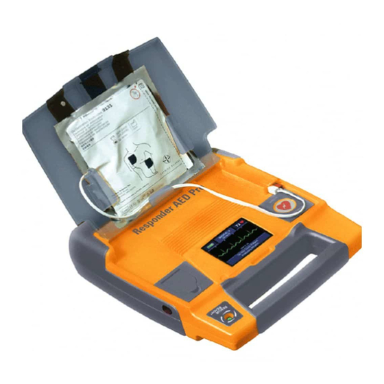
SECTION 3 – MAINTENANCE AND TROUBLESHOOTING SECTION 2 - INTRODUCTION OVERVIEW This section presents information about the AED, its use, and the training requirements for operation. Topic Page # AED Description Indications for Use / Intended Use RHYTHMx AED ECG Analysis Algorithm Rescue Protocol Operator Training Requirements Intellisense Battery... -
Page 15: Rhythmx® Aed Ecg Analysis Algorhithm
All rhythms below this rate will be classified as non-shockable. This rate is programmable between 120 bpm (beats per minute) and 240 bpm via ServiceLink Software by the Medical Director. The default Detection Rate is 160 bpm. The Responder AED detection rate is 160 bpm. ASYSTOLE THRESHOLD The asystole baseline-to-peak threshold is set at 0.08 mV. - Page 16 All SVT rhythms above the rates will be classified as shockable. The SVT Rate must be greater than the Detection Rate and is selectable by Service between 160 and 300 bpm or, “NO THERAPY FOR SVT” can be selected via ServiceLink Software by the Medical Director on the Responder AED only. 2022100-201 Rev C ©...
-
Page 17: Rescue Protocol
SECTION 3 – MAINTENANCE AND TROUBLESHOOTING RESCUE PROTOCOL The AED Rescue protocol is consistent with the guidelines recommended by the American Heart Association (AHA) , European Resuscitation Council (ERC), and the International Liaison Committee on Resuscitation (ILCOR). Upon detecting a shockable cardiac rhythm, the AED advises the operator to press the SHOCK button to deliver a shock and then advises the operator to start CPR. -
Page 18: Intellisense® Battery
Lithium BATTERY SHELF LIFE The Responder AED batteries have a shelf-life of five years. Shelf-life is defined as the length of time a battery can be stored, prior to installation into AED, without degrading its performance. Note: Storing the battery outside its specific range (0-50°C) will decrease battery life. - Page 19 The exposed side of the battery should be flush with the outside of the AED case. 3. For the Responder AED, open the lid for 5 seconds to initiate self-test. If the battery is installed properly, the STATUS INDICATOR will turn GREEN. Close the lid.
-
Page 20: Pads
AED at all times. Refer to the electrode package label for operation temperatures. On the Responder AED, an audible and visual alert will indicate after the self-test if the pads are missing, unplugged or damaged. CAUTION: Possible Improper AED Performance Using pads that are damaged or expired may result in improper AED performance. -
Page 21: Aed Indicators
The following indicators are located on the AED. RESCUEREADY® STATUS INDICATOR The STATUS INDICATOR is located on the Responder AED handle. When this indicator is GREEN, the device is RescueReady. This means the Responder AED self-tests have verified the following: Battery has an adequate charge. - Page 22 SECTION 3 – MAINTENANCE AND TROUBLESHOOTING SMARTGAUGE™ BATTERY STATUS INDICATOR The SmartGauge Battery Status Indicator has five (5) LEDs, four (4) green and one (1) red. The right four green LEDs display the remaining capacity of the battery much like a fuel gauge.
-
Page 23: Setting The Aed Internal Clock
SECTION 3 – MAINTENANCE AND TROUBLESHOOTING CONTINUE INDICATOR The word CONTINUE will illuminate yellow and the continue button indicator LED will illuminate red when the previous rescue data has not been cleared from the internal memory. Note: Only for AEDs not equipped with Multiple Rescue software TEXT DISPLAY The text display has 2 lines of text. -
Page 24: Section 3: Maintenance & Troubleshooting
During this test the AED monitors the ability to charge, charge time, and voltage level. When the Responder AED requires maintenance, audible and/or visual indicators are activated. By monitoring the visual and audible indicators, the user can be assured that the Responder AED is ready to conduct a rescue. -
Page 25: Indicator Troubleshooting Table
DAILY MAINTENANCE Check the STATUS INDICATOR to ensure that it is GREEN. When the indicator is GREEN, the Responder AED is ready for a rescue. If the indicator is RED, refer to the Troubleshooting Table in this chapter. MONTHLY MAINTENANCE Open the AED lid. - Page 26 SECTION 3 – MAINTENANCE AND TROUBLESHOOTING ANNUAL MAINTENANCE Perform the following tests annually to confirm that the diagnostics are functioning properly and to verify the integrity of the case. Check the Integrity of the Pads and Circuitry Open the AED lid. Remove the pads.
-
Page 27: Authorized Repair Service
SECTION 3 – MAINTENANCE AND TROUBLESHOOTING AUTHORIZED REPAIR SERVICE The AED has no user-serviceable internal components. Try to resolve any maintenance issues with the AED by using the Troubleshooting Table presented in this chapter. If you are unable to resolve the problem, contact Customer Service. -
Page 28: Section 4: Techincal Data
OVERVIEW This section presents technical data about the AED. Topic Page # Parameters Safety and Performance Standards STAR Biphasic Waveform STAR Biphasic Energy Protocols for Responder AED RHYTHMx ECG analysis performance PARAMETERS OPERATION Semi-Automatic (shock advisory) AUDIBLE ALERTS Voice Prompt... - Page 29 4 Years Up to 290 shocks Lithium The battery operating life depends on the type of battery (9142 for Responder AED), actual usage and environmental factors. BATTERIES AND CAPACITOR CHARGE TIMES A new battery typically takes 10 seconds to charge the AED to maximum energy.
-
Page 30: Safety And Performance Standards
AED MODEL 2019198 The AED has been designed and manufactured to conform to the highest standards of safety and performance including electromagnetic compatibility (EMC). The Responder AED Model 2019198 and pads conform to the applicable requirements of the following: CE Marked by BSI 0086 per the Medical Device Directive 93/42/EEC of the... - Page 31 SECTION 4 – TECHNICAL DATA EMISSIONS Field Standard or Compliance IEC 55011/CISPR 11, Group 1, Class B Magnetic ANSI/AAMI DF39, <0.5mT on surface, except for within 5cm of the lid magnet and the speaker IMMUNITY Field Standard or Compliance IEC 61000-4-3, Level X, (20V/m) IEC 60601-2-4, Section 36.202.3 (20-V/m) AAMI DF39, Section 3.3.21.2.1 Magnetic...
-
Page 32: Star Biphasic Waveform
SECTION 4 – TECHNICAL DATA STAR BIPHASIC WAVEFORM The waveform generated by the Responder AED is a Biphasic Truncated Exponential waveform that is compliant with ANSI/AAMI DF2 and DF39. The following is a graph of the waveform voltage as a function of time when the AED is connected to a 50-Ohm resistive load. - Page 33 1434 1007 108-146 1437 1027 102-138 1439 1040 98-132 1441 10.8 1049 95-128 Table A2 – Low Variable Energy (200 VE) Waveform Responder AED Waveform Phase 1 Phase 2 Patient’s Voltage* Duration* Voltage* Duration* Energy** Impedance (Volts) (ms) (Volts) (ms)
-
Page 34: Star Biphasic Energy Protocols For Responder Aed
The operator, with guidance, direction and implementation from the designated AED program Medical Director, may select from one of these five protocols when placing the Responder AED into service. The Responder AED’s factory default energy protocol is 200-300-300 Joule (J) escalating Variable Energy (VE). - Page 35 SECTION 4 – TECHNICAL DATA These protocols are selected by using our ServiceLink software program. The five biphasic energy protocols available are as follows: Energy Level (VE) Energy Range Energy Protocols Shock Sequence Factory Default 126-260 170-351 170-351 Protocol #2 126-260 126-260 170-351...
-
Page 36: Rhythmx Ecg Analysis Performance
SECTION 4 – TECHNICAL DATA RHYTHMX ECG ANALYSIS PERFORMANCE The AED RHYTHMx ECG Analysis system analyzes the patient’s ECG and advises you when the AED detects a shockable or non-shockable rhythm. This system makes it possible for a person, with no training in the interpretation of ECG rhythms, to offer defibrillation therapy to victims of sudden cardiac arrest.