Advertisement
Quick Links
Advertisement

Related Manuals for Honeywell SLATE R8001U3001


Summary of Contents for Honeywell SLATE R8001U3001
- Page 1 SLATE ™ Analog I/O Module R8001U3001 INSTALLATION INSTRUCTIONS...
- Page 2 Scan for more information...
-
Page 3: Specifications
Application SLATE™ brings configurable safety and programmable logic together into one single platform. The platform can easily be customized for almost any requirement or application–offering virtually limitless development opportunities with far less complexity. The R8001U3001 SLATE Analog I/O module provides analog input and output capability for all combustion applications. - Page 4 Mounting DIN Rail (See Fig. 2) Required Components R8001A1001 SLATE Base Controller R8001S9001 SLATE Sub-Base Module 7-3/32 (181) 2-11/16 (68) 4-19/32 (117) M35382 Fig. 1. Mounting dimensions of analog I/O module in in. (mm). 32-00009—01...
-
Page 5: Principal Technical Features
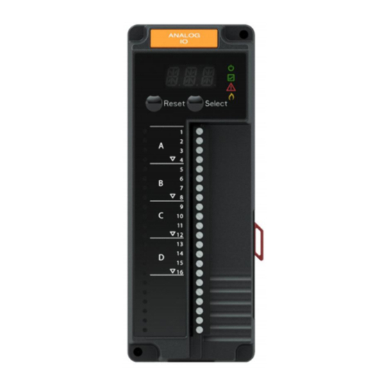
Principal Technical Features The R8001D4001 analog I/O module provides analog input and output capability for all combustion applications. LED Array There are four LEDs on the front of the analog I/O module that provide quick identification of system status and problems. This status is broadcast to other modules on the platform bus in case they are affected by the inoperable module(s). -
Page 6: Installation
Select and Reset Buttons The SLATE system modules have a Select and Reset buttons located on the front of the module and beneath the segment display. The Reset button is used to clear a lockout and reset the module. The Select button is used to scroll through the segment display information. - Page 7 M35383 Fig. 2. Installing the Analog I/O Module on the Sub-Base Module. 2. Wiring must comply with all applicable codes, ordinances and regulations. 3. Wiring must comply with NEC Class 1 (Line Voltage) wiring. IMPORTANT 1. This equipment generates, uses and can radiate radiofrequency energy and, if not installed and used in accordance with these instructions, may cause interference for radio communications.
- Page 8 2. This digital apparatus does not exceed the Class A limits for radio noise, set out in the Radio Interfeence Regulations of the Canadian Department of Communications. 3. Cable shield must be terminated to ground at both ends. If shielded cable is NOT used, use three-wire twisted cable. Wiring WARNING Electrical Shock Hazard.
- Page 9 ANALOG INPUT OUTPUT MODULE UNIVERSAL 4 CELLS LOW VOLTAGE CELL UNIVERSAL LOW VOLTAGE CELL UNIVERSAL LOW VOLTAGE CELL UNIVERSAL LOW VOLTAGE CELL M35287 Fig. 3. Wiring diagram for Analog I/O Module. SLATE ANALOG I/O MODULE ™ R8001U3001...
- Page 10 Terminal Description Rating Cell A (T1) See Tables Table 4-Table 7 for configuration options Cell A (T2) See Tables Table 4-Table 7 for configuration options Cell A (T3) See Tables Table 4-Table 7 for configuration options Cell A (T4) See Tables Table 4-Table 7 for configuration options Cell B (T5) See Tables Table 4-Table 7 for configuration...
- Page 11 Specifications based on worst case over ambient temperatures. Basic Functions Typical Max Units Voltage In Range 15.0 Resolution 2.43 mV DC Null -25.0 25.0 mV DC Accuracy -25.0 25.0 mV DC Whichever is greater -1.0 Range 15.0 Resolution mV DC Null 100.0 - 100.0 mV DC...
- Page 12 Complex Functions Min Typical Max Units Thermocouple Type J Range -200.0 - 1025.0 °C Resolution °C & Accuracy -5.0 °C Type K Range -150.0 - 1000.0 °C Resolution °C Accuracy -5.0 °C PT100 Range -135.0 - 250.0 °C 3 wire, 100 Ω Resolution °C &...
- Page 13 Frequency / PWM Typical Max Units Functions PWM Out Amplitude 10.0 Low output state = 0V Frequency 100.0 - 1000.0 Hz Duty Cycle 98.0 Allowable output %DC Resolution Accuracy -0.5 10V amplitude Frequency In Amplitude 10.0 15.0 Range 1000 Min. “on” pulse width 50.0 usec 10V amplitude...
- Page 14 Configuration Optimum Range for Performance Max Thermocouple J -50°C 1025°C ± 4 °C K -50°C 1000°C ± 4 °C -135°C 250°C ± 2 °C 25°C 125°C ± 1°C Current Out 4 mA 20 mA ± .05 mA Voltage: In / Out 10 V 0.3 %, typical...
- Page 15 Signal ground Note the 18V system ground is not electrically connected to earth ground. Follow local codes and appliance recommendations to determine if this should be connected to earth ground. Be sure loads do not exceed the terminal ratings. Refer to the labels or terminal ratings in Table 3.
- Page 16 SLATE User Guide document located on our website at http://combustion.honeywell.com/SLATE Automation and Control Solutions Honeywell International Inc. ® U.S. Registered Trademark. 1985 Douglas Drive North © 2014 Honeywell International Inc. Golden Valley, MN 55422 32-00009—01 M.S. 12-14 customer.honeywell.com Printed in U.S.A.