
Related Manuals for Honeywell Notifier AMPS-24/E


Summary of Contents for Honeywell Notifier AMPS-24/E
- Page 1 Intelligent Power Supply AMPS-24/E Manual Document 51907 02/26/2014 Rev: P/N 51907:J2 ECN 14-0161...
- Page 2 Fire Alarm & Emergency Communication System Limitations While a life safety system may lower insurance rates, it is not a substitute for life and property insurance! An automatic fire alarm system—typically made up of of detector is necessarily best and a given type of detector smoke detectors, heat detectors, manual pull stations, audible may not provide adequate warning of a fire.
-
Page 3: Installation Precautions
HARSH™, NIS™, and NOTI•FIRE•NET™ are all trademarks; and Acclimate® Plus, FlashScan®, NION®, NOTIFIER®, ONYX®, ONYXWorks®, UniNet®, VeriFire®, and VIEW® are all registered trademarks of Honeywell International Inc. Echelon® is a registered trademark and LonWorks™ is a trademark of Echelon Corporation. ARCNET® is a registered trademark of Datapoint Corporation. Microsoft® and Windows® are registered trademarks of the Microsoft Corporation. - Page 4 •Brief description of content you think should be improved or corrected •Your suggestion for how to correct/improve documentation Send email messages to: FireSystems.TechPubs@honeywell.com Please note this email address is for documentation feedback only. If you have any technical issues, please contact Technical Services.
-
Page 5: Table Of Contents
Table of Contents Section 1: Introduction......................7 1.1: Features................................7 1.2: Specifications..............................7 1.2.1: CPS-24 Board ............................7 1.2.2: AMPS-K2 Board ..........................8 1.3: Installation Standards and Codes........................9 1.3.1: UL 9th Edition Compliance.........................9 1.4: Related Documentation ..........................10 1.5: Notes, Cautions, and Warnings........................10 1.6: Board Layout ...............................11 1.7: LED Indicators.............................12 Section 2: Installation ...................... - Page 6 Table of Contents 4.1.2: Calculation for Main Supply Current ....................42 4.1.3: Calculating the Maximum Secondary Power Non-Fire Alarm Current Draw ........43 4.1.4: Calculating the Maximum Secondary Power Fire Alarm Current Draw ..........43 4.2: Calculating the Battery Requirements ......................44 4.2.1: Calculating the Battery Capacity .......................44 4.2.2: Calculating the Battery Size ......................45 Appendix A: Compatibility with Other Systems ..............
-
Page 7: Section 1: Introduction
Section 1: Introduction The AMPS-24/E is an intelligent power supply and battery charger with one 5VDC and three 24 VDC outputs. It can connect directly to a CPU2-3030*, NCA-2 or DS-DB via a harness cable with EIA-485 connections. For other systems it can operate in FlashScan or CLIP (Classic Loop Interface Protocol) mode and reside on the SLC. -
Page 8: 2: Amps-K2 Board
Introduction Specifications Charging current: 1.0A, 2.0A, 5.0A, or OFF (Software selectable) Based on battery size programming (See “Outputs Current Settings” on page 35) Charging voltage: 27.6 VDC (nominal) To calculate expected standby operating times, see Section 4 on page 41. When AC power is lost, the deeply-discharged battery cutoff protection will be invoked at 17 volts. -
Page 9: Installation Standards And Codes
Installation Standards and Codes Introduction 1.3 Installation Standards and Codes The AMPS-24/E complies with the following standards: NFPA 72 National Fire Alarm Code Underwriters Laboratories: • UL 864 Standard for Control Units and Accessories for Fire Alarm Systems • UL 2572 Standard for Mass Notification Systems Underwriters Laboratories of Canada (ULC): •... -
Page 10: Related Documentation
Introduction Related Documentation 1.4 Related Documentation To obtain a complete understanding of specific features of the AMPS-24, or to become familiar with functions in general, make use of the documentation listed in Table 1.2. Title Document Number NFS2-3030 Installation, Operation, and Programming Manuals 52544, 52546, 52545 NFS-3030 Installation, Operation and Programming Manuals 51330,51344, 51345... -
Page 11: Board Layout
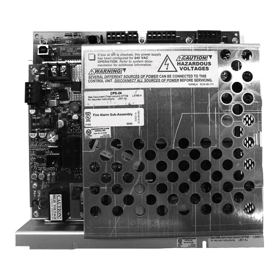
Board Layout Introduction 1.6 Board Layout The AMPS-24 is comprised of two boards; the AMPS-K2 (the larger rear board), and the CPS-24 (the smaller front board). Figure 1.1 below illustrates the layouts for these boards. Figure 1.2 illustrates the positions of the LEDs. +24V AUX 24 Use supplied... -
Page 12: Led Indicators
Introduction LED Indicators 1.7 LED Indicators MAIN 24 TBL 485RX LED 11 SLCRX LED 9 AUX 24 TBL LED 6 MAIN 24 STATUS LED 12 LED 10 LED 2 SLCTX 485TX AUX 24 LED 7 LED 8 TBL BUS LED 13 LED 5 RESET LED 3... - Page 13 LED Indicators Introduction There are eighteen LEDs that indicate various conditions and troubles. The following table lists and describes each. Reference LED Name Color Description • +5V logic power and software indication • Normally slow blink (1 blink/sec) STATUS Green •...
-
Page 14: Section 2: Installation
Section 2: Installation WARNING: High Voltages Present! Use extreme caution when working with the AMPS-24. High voltage and AC line-connected circuits are present in this power supply. Turn off and remove all power sources. To reduce the risk of electric shock, make sure to properly ground the AMPS-24. -
Page 15: In An Eq Series Backbox
In an EQ Series Backbox Installation 2.2 In an EQ Series Backbox WARNING: Risk of equipment damage! Refer to the Heat Dissipation Calculation Document to determine the acceptable heat dissipation in the EQ Series cabinets when digital audio products are present. The AMPS-24 mounts on a CHS-6 chassis into any EQ Series cabinet row. -
Page 16: In A Bb-25 Cabinet
Installation In a BB-25 Cabinet 2.3 In a BB-25 Cabinet The AMPS-24 mounts in the left side of a BB-25 cabinet. Two 26 amp-hour batteries fit into the right side of the cabinet. A BB-100 or BB-200 cabinet is required for batteries larger than 26 amp-hour. -
Page 17: In A Bb-200 Cabinet
In a BB-200 Cabinet Installation 2.5 In a BB-200 Cabinet Fasten the AMPS-24 chassis to the backbox using the two supplied #4-40 keps nuts (p/n 36045) at these positions. Figure 2.5 BB-200 Mounting The AMPS-24 mounts in a BB-200 cabinet with four 100 amp-hour batteries (two on the top shelf and two on the bottom). -
Page 18: Cabinet Wiring Examples
Installation Cabinet Wiring Examples 2.6 Cabinet Wiring Examples The terminal block and pin connections are illustrated in Figure 1.1. Power-limited (Class 2) wiring must remain separated from nonpower-limited wiring by at least 0.25 in. (6.4 mm), and must enter an enclosure through different knockouts. TB1 (Main 24V) and TB3 (AUX 24) on the AMPS-K2 board are power-limited (Class 2) when set for 3A maximum current in the programmed database. - Page 19 Cabinet Wiring Examples Installation TB1 - Main 24V power to panel. The BB-100 cabinet must be Power-limited (Class 2). located less than 20 feet (6.1 TB2 - Secondary Power 5V and TB2 - SLC Circuit Wiring - Power-limited m) from the enclosure 24V Auxiliary outputs.
-
Page 20: Wiring The Amps-24/E
Installation Wiring the AMPS-24/E 2.7 Wiring the AMPS-24/E WARNING: Risk of electrical shock! Remove all power sources to equipment while connecting electrical components. Leave the external, main power breaker OFF until installation of the entire system is complete. WARNING: Risk of equipment damage! Several sources of power can be connected to the control panel and/or power supply. -
Page 21: 2: Connecting Tb1 Main 24V
Wiring the AMPS-24/E Installation TB2 - Accessories Output Power-limited (Class 2); 24V @ 0.5A, 5V @ 0.15A. TB3 - Secondary Output Source (Batteries) 24VDC from batteries installed in the appropriate enclosure. Secondary (battery) power is required to support the system during loss of primary power. 2.7.2 Connecting TB1 MAIN 24V To a Control Panel, Network Annunciator, or DS-DB This output provides filtered, power-limited (Class 2)(when set for less than 5A) 24VDC power to... - Page 22 Installation Wiring the AMPS-24/E • DVC Series • NCM-W/F • DS-DB Digital Series board (+/- 485 terminals must be connected). +24V +24V COM +485 - 485 COM +24V +24V MAIN 24V Figure 2.11 Connecting to the Main 24 Output TB1, Example 2 Figure 2.12 is a block diagram representing an application where an AMPS-24 is used as a general purpose remote power supply and battery charger.
-
Page 23: 3: Connecting To The Aux 24 Output
Wiring the AMPS-24/E Installation 2.7.3 Connecting to the AUX 24 Output TB3 - This output supplies one non-resettable, power-limited (Class 2) (when set for less than 5A), filtered 24VDC circuit available to power external devices. It may be used to power the DS-DB when connected to TB24 on the DS-DB. -
Page 24: 5: Connecting The Trouble Bus
Installation Wiring the AMPS-24/E 2.7.5 Connecting the Trouble Bus Trouble bus input is designed to receive trouble signals from any normally-open dry TBL BUS contacts or open-collector circuit. Figure 2.15 Trouble Bus Connection 2.7.6 Connecting the Accessories Output on the CPS-24 TB2 - Supplies one (1) non-resettable, power-limited (Class 2) 24 VDC circuit and one non-resettable power-limited (Class 2) 5 VDC circuit available to power external devices. -
Page 25: Installing And Connecting The Batteries
Installing and Connecting the Batteries Installation • Overcurrent protection for the AC branch circuit must comply with Article 760 of the National Electrical Codes, as well as local codes. • Use 12–14 AWG (3.31 mm – 2.08 mm ) or larger wire with 600 VAC insulation for the AC branch circuit. -
Page 26: 1: Setting The Charger
Installation Installing and Connecting the Batteries Certain system designs may require connecting two or four batteries to the power supply, connecting multiple power supplies to each other, or connecting one set of batteries to multiple power supplies. Always use wire size 12-18 AWG (3.25 mm –... - Page 27 Installing and Connecting the Batteries Installation To determine battery requirements, refer to Section 4 of this manual. Figure 2.20 Connecting Four Batteries to the Power Supply NOTE: Use a ring terminal to attach two cables to one battery terminal. AMPS-24 Manual — P/N 51907:J2 02/26/2014...
-
Page 28: 4: Connecting Multiple Power Supplies/Products (Separate Batteries)
Installation Installing and Connecting the Batteries 2.8.4 Connecting Multiple Power Supplies/Products (Separate Batteries) Follow these guidelines when connecting multiple power supplies and products that use batteries (such as the DS-AMP and DAX): • Disable Ground Fault detection on all products except one power supply. See Figure 1.1 on page 11. -
Page 29: 5: Connecting Multiple Power Supplies/Products (One Set Of Batteries)
Installing and Connecting the Batteries Installation 2.8.5 Connecting Multiple Power Supplies/Products (One Set of Batteries) Certain system designs may require connecting multiple power supplies and products that use batteries (such as the DS-AMP and DAX) to one set of batteries. Follow these connection guidelines: •... -
Page 30: Section 3: Configuring The Amps-24
Section 3: Configuring the AMPS-24 3.1 SLC Addressing NOTE: An AMPS-24 communicating over the EIA-485 protocol will not require an SLC address block. See Section 3.3, “Configuring the Network Annunciator” for more information. When the AMPS-24 communicates via the SLC, the installer must reserve sequential SLC addresses (an address block) equal to the number of addresses that will be consumed by the AMPS-24. -
Page 31: 2: Setting The Base Address (Slc Enabled)
SLC Addressing Configuring the AMPS-24 3.1.2 Setting the Base Address (SLC Enabled) The base address is the first address used in an SLC address block. Combine rotary switch (SW2) and address switch (SW3) settings to determine the base address (B). The base address will be a number that ends in zero or five and the rest of the address block will progress sequentially from that number until all the addresses in the block are consumed. -
Page 32: Programming The Amps-24
Configuring the AMPS-24 Programming the AMPS-24 Figure 3.1 below gives two examples of setting the base address with both rotary and slider switch settings. SLC ADDRESSES ROTARY BASE SELECTED SWITCH SLIDER SWITCH ADDRESS with SETTING POSITION five AMPS-24 Addresses 120-124 Figure 3.1 SLC Address Selection 3.2 Programming the AMPS-24 Use PK-PPS to program the charger current and trouble reporting. -
Page 33: 2: Establishing The Hardware Connection
Programming the AMPS-24 Configuring the AMPS-24 Windows XP Professional with SP2 Windows 2000 with SP4 On the Found New Hardware Wizard window, select “No, On the Found New Hardware Wizard window, click Next. not this time”. Click Next. Select “Search for a suitable driver for my device”. Click Select “Install from a list or specific location”. -
Page 34: 4: Working Online
Configuring the AMPS-24 Programming the AMPS-24 To create a new database, select from the menu, then select AMPS-24. To edit an existing database, select from the menu, then select AMPS-24. OPEN Refer to Figure 3.3 below. Select AMPS-24 from drop-down menu. - Page 35 Programming the AMPS-24 Configuring the AMPS-24 The worksheet’s summary section displays all selections. When programming is complete, PK-PPS displays the SLC address consumption that is the result of your selections. Figure 3.4 PK-PPS: Label Label For greater ease of identification, you may create a label for each power supply. Labels may have a maximum of 40 characters.
-
Page 36: Trouble Reporting
Configuring the AMPS-24 Programming the AMPS-24 Figure 3.6 PK-PPS: Interface Type Interface Type Select the interface type. SLC: This must be selected when the AMPS-24 is used as the power supply for a CPU2-3030 or as a remote power supply. EIA-485: This must be selected when the AMPS-24 is used with an NCA-2. -
Page 37: Configuring The Network Annunciator
Configuring the Network Annunciator Configuring the AMPS-24 US AC Fail Delay time: Make a selection ( , or ) from the drop- HOURS HOURS HOURS down menu. Figure 3.8 PK-PPS: Summary Summary The Summary screen displays all of your previous selections and the resulting SLC address consumption. -
Page 38: 2: Software Type Id Codes
Configuring the AMPS-24 Configuring the FACP switch selection and in the order given in Table 3.3. Each SLC address may also be programmed manually at the panel or through the VeriFire Tools utility. Note that either one or five addresses can be associated with the power supply depending on the configuration. - Page 39 Notes AMPS-24 Manual — P/N 51907:J2 02/26/2014...
- Page 40 Notes AMPS-24 Manual — P/N 51907:J2 02/26/2014...
-
Page 41: Section 4: Power Supply Calculations
Section 4: Power Supply Calculations Calculations must be done to determine standby and alarm DC current loads. Ampere-hour requirements must be calculated as well to determine battery size. The AMPS-24 provides filtered 24VDC (nominal) power that may be used for operating external devices. -
Page 42: 2: Calculation For Main Supply Current
Power Supply Calculations Calculating the System Current Draws 4.1.2 Calculation for Main Supply Current Calculation Column 1 Calculation Column 2 Calculation Column 3 Quantities Primary, Non-Fire Alarm Primary, Fire Alarm Secondary, Non-Fire Alarm Current (amps) Current (amps) Current (amps) Total on: Total on: Total on: X [current... -
Page 43: 3: Calculating The Maximum Secondary Power Non-Fire Alarm Current Draw
Calculating the System Current Draws Power Supply Calculations 4.1.3 Calculating the Maximum Secondary Power Non-Fire Alarm Current Draw Use the table below to determine the maximum current requirements of the secondary power source during non-fire alarm conditions. The result obtained is the amount of current that the batteries must be able to supply to the fire alarm system. -
Page 44: Calculating The Battery Requirements
Power Supply Calculations Calculating the Battery Requirements 4.2 Calculating the Battery Requirements 4.2.1 Calculating the Battery Capacity Use this table to determine the battery capacity needed for the system: Current (amps) Time (hours) _________AH Secondary Non-Fire Required Secondary Non-Fire Alarm Alarm Current (from Standby Time (24 or 60 hours) Table 4.2) -
Page 45: 2: Calculating The Battery Size
Calculating the Battery Requirements Power Supply Calculations 4.2.2 Calculating the Battery Size Use this table to choose the battery size, in amp-hours, needed to support the fire alarm system. The AMPS-24 can charge batteries from 7 to 200 AH. Select batteries that meet or exceed the Total Amp-Hours calculated in Table 4.4 and that are within the acceptable battery charger range. -
Page 46: Appendix A: Compatibility With Other Systems
A.1.1 Power Supply Calculations Table A.1 on the following page provides Honeywell-specific current draw calculations for devices powered by the AMPS-24. This table replaces Table 4.1 on page 42 when AMPS-24 is used to power XLS3000 systems. -
Page 47: A.1.2: Calculation For Main Supply Current
XLS3000 Compatibility with Other Systems A.1.2 Calculation for Main Supply Current Calculation Column 1 Calculation Column 2 Calculation Column 3 Quantities Primary, Non-Fire Alarm Primary, Fire Alarm Secondary, Non-Fire Alarm Current (amps) Current (amps) Current (amps) Total on: Total on: Total on: X [current X [current... -
Page 48: Index
Index Numerics 24VDC 41 General purpose power 21 unsupervised output 20 Ground fault detection 28 485 21 grounding the AMPS-24 14 AC loss detection, delay 7 Heat Dissipation Calculation Document 10 Address block 30 address block 30 address decade 31 Installation Addressing 30 in a BB-100 Cabinet 16... - Page 49 Index R–X – Power supply calculations 41 see also XLS3000 Rotary Switch 31 setting address decade 31 Selectable charger current see also Charge Selection Switch self-threading screws 14 SLC 23 Address Selection 32 determining address block size 30 Wiring 20 Snap-on cover 14 Specifications 7 AC power 7...
- Page 50 X–X Index AMPS-24 Manual — P/N 51907:J2 02/26/2014...
- Page 51 Manufacturer Warranties and Limitation of Liability Manufacturer Warranties. Subject to the limitations set forth herein, Manufacturer warrants that the Products manufactured by it in its Northford, Connecticut facility and sold by it to its authorized Distributors shall be free, under normal use and service, from defects in material and workmanship for a period of thirty six months (36) months from the date of manufacture (effective Jan.
- Page 52 World Headquarters 12 Clintonville Road Northford, CT 06472-1610 USA 203-484-7161 fax 203-484-7118 www.notifier.com...