Advertisement
APPLICATION
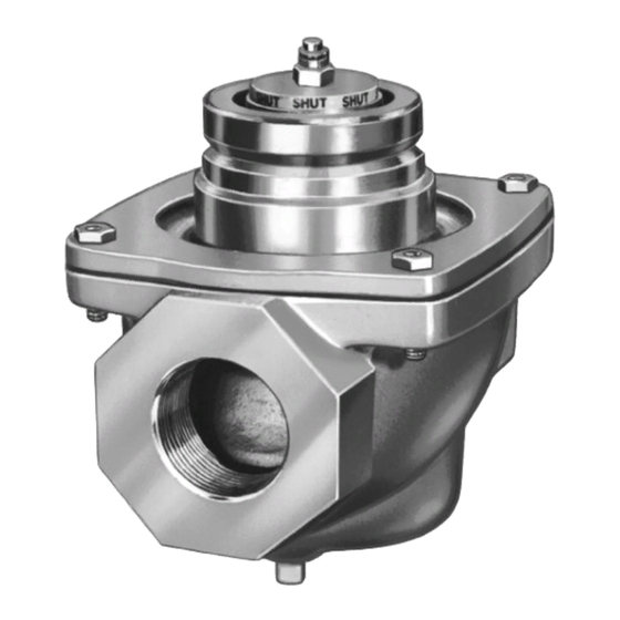
The V5055 Gas Valves are used with the V4055, V4062,
and V9055 Fluid Power Actuators to control gas flow to
commercial and industrial burners.
® U.S. Registered Trademark
© 2004 Honeywell International Inc.
All Rights Reserved
Industrial Gas Valves
FEATURES
• Used with natural or liquefied petroleum (LP) gases.
• V5055 normally closed valves are rated for final shutoff
service (safety shutoff).
• V5055A,C,D,E Valves are for On-Off service.
• V5055B Valve has a characterized guide and in
combination with the V4055, V4062, and V9055 Fluid
Power Actuators, provides slow-opening, hi-lo-off,
and modulating functions respectively.
• V5055C,E,F Valves have a double seal and are used
with V4055D,E Actuators to provide proof-of-closure
switch and valve seal overtravel interlock.
• V5055D,E,F Valves are for high pressure applications
(see Table 1).
• Seven valve sizes from 3/4 to 3 inches have NPT
threaded connections. Models are available with
BSP-PL threads. V5055A,B,C Valves are available
in a 4 inch size and have flange connections.
• Most models have 1/4 inch upstream and downstream
tap and plug. BSP-PL thread models have 1/4 inch
upstream tap and plug.
• Valve body rating of 75 psi (517.1 kPa).
• Yellow SHUT indicator attached to the valve stem
provides an indication of the valve closed position.
• Unpainted, die-cast aluminum body.
Application ........................................................................
Features ...........................................................................
Specifications ...................................................................
Ordering Information .........................................................
Gas Valve Sizing ..............................................................
To Size Two Identical Valves Piped In Series ...................
Installation ........................................................................
Operation and Checkout ..................................................
Service Information ..........................................................
V5055A-F
PRODUCT DATA
Contents
1
1
2
2
4
4
6
7
9
Put UPC Code Here
60-2307—15
Advertisement
Table of Contents

Related Manuals for Honeywell V5055A


Summary of Contents for Honeywell V5055A
- Page 1 • Used with natural or liquefied petroleum (LP) gases. • V5055 normally closed valves are rated for final shutoff service (safety shutoff). • V5055A,C,D,E Valves are for On-Off service. • V5055B Valve has a characterized guide and in combination with the V4055, V4062, and V9055 Fluid Power Actuators, provides slow-opening, hi-lo-off, and modulating functions respectively.
-
Page 2: Specifications
If you have additional questions, need further information, or would like to comment on our products or services, please write or phone: 1. Your local Honeywell Automation and Control Products Sales Office (check white pages of your phone directory). 2. Honeywell Customer Care... - Page 3 V5055A-F INDUSTRIAL GAS VALVES Ambient Operating Temperature Rating: Material: Die-cast aluminum. -40°F to 150°F (-40°C to 66°C); -40°F to 125°F (-40°C to 52°C) when used with V9055. Mounting: Mounts directly in the gas supply line. Table 2. Valve Rated Capacity.
-
Page 4: Gas Valve Sizing
V5055A-F INDUSTRIAL GAS VALVES Replacement Parts: V4055 or V4062 with V5055A1145, A1152, A1160, Replacement Seal Assembly: Includes valve seal, bonnet A1178, B1168, B1184, B1192, B1200, B1218. seal, and tube of lubricant. Australian Gas Association Approved: 133393A: for 3/4, 1, 1-1/4, and 1-1/2 in. valves V5055B1267, B1275, and B1291. - Page 5 V5055A-F INDUSTRIAL GAS VALVES 6-3/4 (172) 3-23/32 (95) 5 (127) 27/32 (21) KNOCKOUT FOR1/2 INCH CONDUIT (4) 1-9/32 (33) 1/4 INCH NPT DOWNSTREAM OCTAGON TAP AND PLUG 1/4 INCH NPT UPSTREAM TAP AND PLUG ALLOW 2 IN. (51 mm) CLEARANCE FOR ACTUATOR REMOVAL.
-
Page 6: Installation
V5055A-F INDUSTRIAL GAS VALVES INSTALLATION WARNING Electrical Shock Hazard and Explosion Hazard. IMPORTANT: Can cause serious injury, death or property The V5055 Valve is designed to provide control damage. of gaseous fuel (natural and LP gas) flow in 1. Turn off gas supply before starting installation. -
Page 7: Operation And Checkout
V5055A-F INDUSTRIAL GAS VALVES Checkout EXCESS DOPE MAY BLOCK TWO CLEAN DISK OFF THREADS, VALVE MODERATE WARNING SEAT AMOUNT OF DOPE Explosion Hazard. LOOSE CHIPS Can cause serious injury, death or property INCORRECT: CORRECT: TOO LONG, NORMAL damage. DISTORTS FULL... - Page 8 V5055A-F INDUSTRIAL GAS VALVES 4 IN. VALVE NUT AND WASHER (NOT INCLUDED) GASKET (2 INCLUDED WITH VALVE) THREADED COMPANION FLANGE (2 - NOT INCLUDED) 5/8 X 3 IN. [76] BOLT (16 - NOT INCLUDED) 4 IN. PIPE M9581 Fig. 6. Installing a 4 in. V5055 Valve.
-
Page 9: Service Information
V5055A-F INDUSTRIAL GAS VALVES SERVICE INFORMATION 4. Remove the leak test tap plug and connect the test apparatus to the Leak Tap (D). 5. Close the downstream manual gas cock (E). 6. Open the upstream manual gas cock (A). WARNING 7. - Page 10 V5055A-F INDUSTRIAL GAS VALVES LARGE SEAL BONNET SEAL SMALL SEAL M9579 Fig. 9. Proper positions of valve and bonnet seals in 4 in. valve.s VALVE SEAL M9578 Fig. 8. Proper positions of valve and bonnet seals in 3/4 through 3 in. valves.
- Page 11 60-2307—15...
- Page 12 V5055A-F INDUSTRIAL GAS VALVES Automation and Control Solutions Honeywell International Inc. Honeywell Limited-Honeywell Limitée 1985 Douglas Drive North 35 Dynamic Drive Golden Valley, MN 55422 Scarborough, Ontario M1V 4Z9 60-2307—15 G.R. Rev. 11-04 www.honeywell.com...