Table of Contents
Advertisement
Advertisement
Table of Contents

Related Manuals for Mitsubishi MA Series


Summary of Contents for Mitsubishi MA Series
- Page 1 < for USA / Canada >...
-
Page 3: Table Of Contents
CONTENTS I. Advantage of New MA Remote Controller Advantage of New MA Remote Con trol ler ................2 1. Weekly Timer ........................2 2. Easy Maintenance Function (Only for Mr. SLIM) ..............2 II. New Functions 3. New Display ........................3 3.1 Dot Liquid Crystal Display (LCD) ........................3 3.2 Multi-language Display ............................ -
Page 4: Advantage Of New Ma Remote Controller
I. Advantage of New MA Remote Controller 1. Weekly Timer The built-in weekly timer enables you not only to make on/off set tings but also temperature set tings. Up to eight pat terns can be set for each day of the week. Saves you money TIME SUN and space because... -
Page 5: New Display
3. New Display Various information is displayed and conveyed clearly, enabling more ac cu rate op er a tion of the air conditioner. 3.1 Dot Liquid Crystal Display (LCD) ● Display example [Operation mode] The dot liquid crystal display enables quick understanding of the op er a tion state. -
Page 6: New Functions
II. New Functions Function Description Go to page Displays information necessary for maintenance. Below information for easy maintenance of air-con di tion er can be dis- played. • Compressor • Accumulated op er at ing time • Number of ON/OFF times •... -
Page 7: Appearance
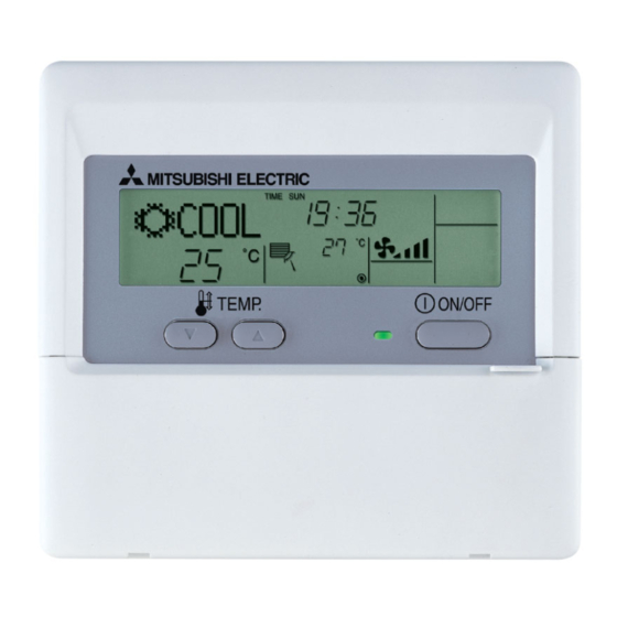
III. Appearance 1. Display Section “Sensor” indication Displayed when the remote con trol ler sensor is used. Day-of-Week For purposes of this ex pla na tion, Shows the current day of the week. all parts of the display are shown as lit. -
Page 8: Easy Maintenance Function (For Mr.slim P Series)
IV. Easy Maintenance Function (For Mr.SLIM P series) ● Reduces maintenance work drastically. ● Enables you to check operation data of the indoor and outdoor units by remote controller. Furthermore, use of maintenance stable-operation control that fixes the operating frequency, allows smooth inspection, even for inverter models. - Page 9 ● Data measurement When the operation is stabilized, measure operation data as explained below. (4) Press the [TEMP] buttons ( ) to select the desired refrigerant address. [Screen (5) Select the type of data to be displayed. After selecting, go to step (6). Compressor information button MENU...
-
Page 10: Guide For Operation Condition
2. Guide for Operation Condition Inspection item Result Check Points Breaker Good Retightened Enter the temperature differences between into Terminal block Outdoor Unit Good Retightened the graph given below. Indoor Unit Good Retightened Operation state is determined according to the plotted areas on (Insulation resistance) the graph. -
Page 11: How To Select Functions Of Remote Controller
V. How to Select Functions of remote controller 1. Function Items The setting of the following remote controller functions can be changed using the remote controller function selection mode. Change the setting when needed. Item 1 Item 2 Item 3 (Setting content) 1.Change Language Language setting to display Display in multiple languages is possible. -
Page 12: Flowchart Of Function Setting
2. Flowchart of Function Setting Setting language (English) Normal display (Display when the air condition is not running) Hold down the button and press the button for 2 seconds. Hold down the button and press the button for 2 seconds. Press the operation mode button. -
Page 13: Screen Structure For Function Setting
3. Screen Structure for Function Setting Description of each screen • Function selection of remote controller : Used to set the timer function and operation limit function, etc. • Set day time : Used to set the current day of the week and time. •... -
Page 14: Function Setting Mode
4. Function Setting Mode 4.1 Change Language The language that appears on the dot display can be selected. The following languages can be selected. English (GB) German (D) Spanish (E) Russian (RU) Italian (I) Chinese (CH) French (F) Japanese (JP) Changing the Display Language ■... - Page 15 Multi Language Display...
-
Page 16: Function Setting
4.2 Function Setting 4.2.1 Operation Lock (Operation Function Limit Setting) The following settings can be made. :All buttons except for the [ON/OFF] button are locked. :All buttons are locked. OFF (default) :No buttons are locked. ON/OFF To activate this operation lock function on the normal screen, hold down the button for two seconds while holding down the FILTER... - Page 17 Enabling the Lock Function (6) While pressing the FILTER ( ) button, press the ON/OFF button for two seconds to enable the operation lock function. appears on the screen (at FUNCTION * If a locked button is pressed while the operation lock function is in use, FUNCTION will blink on the screen (at ■...
-
Page 18: Auto Mode Setting
4.2.2 Auto Mode Setting The following settings can be made. ON (default) : Auto mode is displayed when selecting an operation mode only if the unit to be connected supports the auto mode. However, this does not apply if the unit to be connected does not support the auto mode. Operation mode can be switched: COOL AUTO... - Page 19 ● Screen display when auto mode is set to ON ON/OFF (1) Press the button. The ON lamp lights up and operating contents are displayed on the LCD. MODE (2) Press the button. MODE Each time the button is pressed, the operation mode switches from one to another. “AUTO” is also displayed. COOL AUTO HEAT...
-
Page 20: Temperature Range Limit Setting
4.2.3 Temperature Range Limit Setting The temperature setting range can be limited. It can be limited for each mode. Cool mode : The temperature setting range for cool/dry mode can be changed. Heat mode : The temperature setting range for heat mode can be changed. Auto mode : The temperature setting range for auto mode can be changed. - Page 21 (5) Press the button to select lower limit or upper limit. Lower limit blinks. Upper limit blinks. [Display (6) Press the [TEMP] buttons ( ) to set the desired temperature setting range. [Setting example for lower limit] Display MODE ON/OFF (7) While pressing the button, press the button for two seconds to return to normal mode.
-
Page 22: Basic Functions Setting
4.3 Basic Functions Setting 4.3.1 Remote Controller Main/Sub Setting When using two remote controllers, they must be designated as the main and sub remote controllers. The following settings can be made. MAIN (default) : The remote controller is set as the main controller. : The remote controller is set as the sub controller. -
Page 23: Timer Function Setting (Weekly Timer/Auto Off Timer/Simple Timer)
4.3.2 Timer function setting (Weekly timer/Auto off timer/Simple timer) The following settings can be made. Weekly Timer (default) : The weekly timer can be used. Auto Off Timer : The auto off timer can be used. Simple Timer : The simple timer can be used. Timer Mode Off : Timer mode cannot be used. - Page 24 Setting the Day of the Week and Time ■ Display ex am ple TIME SET (1) Press the [CLOCK] buttons ( ) to display on the screen (at :ENTER ON/OFF (2) Press the button until the desired day of the week appears. [Display (3) Press the [CLOCK] buttons ( ) to set the desired time.
- Page 25 Weekly Timer ■ The weekly timer allows you to set up to eight operations per day of the week. • For each operation, you can set the ON (start) or OFF (stop) timer and temperature. The start timer, stop timer and temperature can also be set individually.
- Page 26 (5) Press the [CLOCK] buttons ( ) to set the desired time. (0:00 to 23:59) [Display ON/OFF (6) Press the button to select whether to start or stop the air conditioner at the time you have set in step (5). [Display (Space) (7) Press the [TEMP] buttons (...
- Page 27 To Turn On the Weekly Timer ON/OFF (1) Press the button so that disappears from the screen (at ● Weekly timer setting procedure To facilitate weekly timer setting, it is recommended that the settings (day of the week, time, operation (on/off)) you are going to make be entered in the setup table shown below.
- Page 28 Auto Off Timer ● The auto off timer begins counting down when the air conditioner starts, and stops the air conditioner when the set time passed. ● The time on the auto off timer can be set in a range of 30 minutes to 4 hours, in 30-minute increments. * By default, the weekly timer is selected as the remoter controller’s timer function.
- Page 29 How to Set the Auto Off Timer ■ Display ex am ple TIMER SET (1)Press the MENU button for 3 seconds so that appears on the screen (at :ENTER [Display TIMER TIMER SET MONITOR :ENTER (2) Press the [CLOCK] buttons ( ) to set the desired time.
- Page 30 To Turn Off the Auto Off Timer… ON/OFF (1) Press the button for 3 seconds so that the timer execution time disappears from the screen (at • If the air conditioner is operated with the auto off timer turned OFF, will appear on the screen (at * The auto off timer will be effective the next time that the air conditioner is operated.
- Page 31 Simple Timer ■ You can set the simple timer in any of three ways. ● Start time only : The air conditioner starts when the set time has passed. ● Stop time only : The air conditioner stops when the set time has passed. ●...
- Page 32 How to Set the Simple Timer ■ Display ex am ple Make sure that “SIMPLE TIMER” is displayed on the screen (at TIMER SET (1) Press the MENU button to select on the screen (at :ENTER TIMER TIMER SET [Display MONITOR :ENTER ON/OFF...
- Page 33 Review the Current Simple Timer Settings (1) Be sure that the “SIMPLE” indicator is displayed on the screen (at TIMER MENU (2) Press the button, so that the appears on the screen (at MONITOR • The time you have set to start or stop the timer appears on the screen (at TIMER MODE (3) Press the...
- Page 34 Timer Mode Off Timer mode cannot be used. ■ Display ex am ple How to set the Timer mode Off MODE ON/OFF (1) While pressing the button, press the button for two seconds to activate the remote controller’s function selection mode. MODE (2) Press the button until appears on the screen (at...
-
Page 35: Contact Number Setting For Error Situation
4.3.3 Contact Number Setting for Error Situation The following settings can be made. CALL • OFF (default) : The preset contact number is not displayed even when an error occurs. CALL • ************ : The preset contact number is displayed when an error occurs. (The contact number can consist of up to 12 digits.) CALL •... - Page 36 MODE ON/OFF (6) While pressing the button, press the button for two seconds to return to normal mode. ON/OFF MODE * If you press the button before the button, the settings you have made will be cancelled. CHECK (7) If you press the (CLEAR) button, the contact number will be displayed for fi...
-
Page 37: Display Change Setting
4.4 Display Change Setting 4.4.1 Temperature Display °F/°C Setting The following settings can be made. ➀ °F(default) : Temperatures are displayed in Fahrenheit. (Degrees F = 1.8 × degrees C + 32) ➁ °C : Temperatures are displayed in Celsius. (Degrees C = (Degrees F - 32) / 1.8) Switching the Temperature Display Unit between °F and °C ■... -
Page 38: Inlet Air Temperature Display Setting
4.4.2 Room air Temperature Display Setting The following settings can be made. ➀ ON (default) : The room air temperature is displayed. ➁ : The room air temperature is not displayed. Setting the Room Air Temperature ■ Display ex am ple MODE ON/OFF (1) While pressing the... -
Page 39: Automatic Cooling/Heating Display Setting
4.4.3 Automatic Cooling/Heating Display Setting • This section explains how to set whether to display “COOL”/“HEAT” in auto mode. It will not be displayed if auto mode is set to OFF. ➀ ON (default) : One of “Automatic cooling” and “Automatic heating” is displayed under the automatic mode is displayed. ➁... -
Page 40: Unit Function Setting By The Remote Controller (For Mr. Slim P Series)
VI. Unit Function Setting by the Remote Controller (for Mr. SLIM P Series) Perform the following settings only to change the functions for Mr. Slim series. (This setting is not possible with the City-Multi series.) Each unit’s functions can be set by a remote controller. Setting of each unit’s functions is possible by remote controller only. Table Functions Available (For details regarding initial settings and operation modes of each unit, refer to the unit installation manual.) (1) Itemised functions of the entire refrigerant system (select unit number 00) - Page 41 (2) Itemised functions of the in door unit (select unit numbers 01 to 03 or AL [Wired remote controller] / 07 Wireless re mote controller]) Settings Function Mode No. Setting No. Check Remarks 100Hr Filter sign 2500Hr "Clean the filter" indicator is not displayed. Quiet Standard Air flow...
- Page 42 [Flow of function selection] First, try to familiarize yourself with the flow of the function selection procedure. In this section, an example of setting the room temperature detection position is given. For actual operations, refer to steps Setting number Refrigerant address Unit number Mode number Modes 01 to 14 can be activated...
- Page 43 [Operating Procedure] Check the setting items provided by function selection. If settings for a mode are changed by function selection, the functions of that mode will be changed accordingly. Check all the current settings according to steps , fill in the "Check" column in Table, and then change them as necessary. For factory settings, refer to the indoor unit's installation manual. Switch off the remote controller.
-
Page 44: Test Run By The Remote Controller (For Mr. Slim P Series)
VII. Test Run by the Remote Controller (for Mr. SLIM P Series) 1. Check Points Under Test Run Before test run • After installation of indoor and outdoor units, piping work and electric wiring work, re-check that there is no refrigerant leakage, loosened connections and incorrect polarity. - Page 45 Press the remote controller’s CHECK button twice to perform self-diagnosis. See the table below for the contents of LCD display.For details,please refer to "VIII.2. Error code list". Contents of inferior phenomena Malfunction indoor unit P1~9 Malfunction indoor unit U1~UP Malfunction outdoor unit F3~F9 Malfunction outdoor unit E0~E5...
-
Page 46: Self-Diagnosis By The Remote Controller (For Mr. Slim P Series)
VIII. Self-Diagnosis by the Remote Controller (for Mr.SLIM) 1. How To Proceed "Self-Diagnosis" 1-1. When a Problem Occurs During Operation If a problem occurs in the air conditioner, the indoor and outdoor units will stop, and the problem is shown in the remote controller display. [CHECK] and the refrigerant address are displayed on the temperature display, and the error code and unit number are displayed alternately as shown below. -
Page 47: Remote Controller Diagnosis
When the error history is reset, the display will look like the one shown below. Press the button twice within three seconds. The self-diagnosis ON/OFF However, if you fail to reset the error history, the error content will be displayed again. address or refrigerant address will blink. -
Page 48: Error Code List
2.Error Code List(for Mr.SLIM P series) <Display function of inspection for outdoor unit> The blinking patterns of both LED1(green) and LED2(red) indicate the types of abnormality when it occurs. Types of abnormality can be indicated in details by connecting an optional part A-Control Service Tool (PAC-SK52ST) to connector CNM on outdoor controller board. - Page 49 Indication Error Outdoor controller board Error Contents Inspection method code LED1 (Green) LED2 (Red) 3 blinking 1 blinking Check if stop valves are open. Abnormality of shell thermostat Check if connectors (TH4, LEV-A) on outdoor controller board are not disconnected. and discharging temperature (TH4) Check if unit fills with specified amount of refrigerant.
-
Page 50: Monitoring The Operation Data By The Remote Controller (For Mr. Slim P Series)
IX. Monitoring the Operation Data by the Remote Controller(for Mr. SLIM) 1.How to "Monitor the Operation Data" Turn on the [Monitoring the operation data] Example) Request code "004" Discharge temperature 156˚F Refrigerant address "00" B: Refrigerant address C: Data display area D: Request code display area (1) Press the button for three seconds so that [Maintenance mode] appears on the screen (at... -
Page 51: Request Code List
2. Request Code List * Certain indoor/outdoor combinations do not have the request code function; therefore, no request codes are displayed. Description Request content Unit Remarks (Display range) Operation state Refer to 2-1. Detail Contents in Request Code. – Compressor-Operating current (rms) 0 –... - Page 52 Description Request content Unit Remarks (Display range) Indoor unit-Control state – Refer to 2-1.Detail Contents in Request Code. Outdoor unit-Control state – Refer to 2-1.Detail Contents in Request Code. Compressor-Frequency control state Refer to 2-1.Detail Contents in Request Code. – Outdoor unit-Fan control state Refer to 2-1.Detail Contents in Request Code.
- Page 53 Description Request content Unit Remarks (Display range) Error history 1 (latest) Displays error history. (" - - " is displayed if no history is present.) Code Error history 2 (second to last) Displays error history. (" - - " is displayed if no history is present.) Code Error history 3 (third to last) Displays error history.
- Page 54 Description Request content Unit Remarks (Display range) Indoor-Fan operating time 0 – 9999 1 hour (After filter is reset) Indoor-Total operating time 0 – 9999 10 hours (Fan motor ON time) Indoor fan output value (Sj value) 0 – 255 Fan control data –...
-
Page 55: Detail Contents In Request Code
2-1. Detail Contents in Request Code Example) Request code "004" Discharge temperature 156˚F Refrigerant address "00" B: Refrigerant address C: Data display area D: Request code display area [Operation state] (Request code ": 0 ") Relay output state Power currently Data display Display Compressor... - Page 56 [Fan control state] (Request code :" 53 ") Data display Fan step correction value by heat sink temperature overheat prevention control Fan step correction value by cool condensation temperature overheat prevention control Display Correction value - (minus) – 1 [Actuator output state] (Request code :"54") Data display Actuator output state Actuator output state...
- Page 57 [Contact demand capacity] (Request code "61") Setting content Data display Setting Display Setting value Setting content SW7-1 SW7-2 100% [External input state] (Request code "62") Input state : Input present Data display Contact demand Silent mode Spare 1 Spare 2 Display Input state input...
- Page 58 [Outdoor unit switch setting display (SW1 to SW10, except SW3)] Request codes: 73 to 82 0: Swich OFF 1: Swich ON 0: Swich OFF 1: Swich ON SW1, SW2, SW6, SW7 Data display Data display 00 00 00 00 00 01 00 01 00 02 00 02...
- Page 59 [Indoor unit – Model setting information] (Request code : 162) Data display Display Model setting state Display Model setting state See the table on the right. PKA-A•GA(L) PKA-A•FA(L) PCA-A•GA PLA-A•AA [Indoor unit – Capacity setting information] (Request code 163 ) Data display Display Capacity setting state...
-
Page 60: System Control (For Mr. Slim P Series)
X. System Control (for Mr. SLIM) VARIETY OF SYSTEM FUNCTION Parts Required in Addition to Standard System System Name System Diagram Features Components (Indoor/Outdoor Units, Remote Controller) There are two types of remote controllers: wired type Indoor unit and wireless type. A.Remote control- Simultaneous twin units are counted as one unit, and ler operation... - Page 61 (Only the microcomputer type Lossnay ventilator Enables control of Remote can be used.) Mitsubishi Lossnay Controller ventilator by remote controller. Connecting the M-NET connection adapter to outdoor M-NET adapter (Option PARTS) unit enables connection of MELANS system control- <Connection with M-NET system>...
-
Page 62: One-Remote Controller (Standard) Operation
1. One Remote Controller (Standard) Operation 1-1 One Wired Remote Controller (OC: Outdoor unit IC: Indoor unit R: Remote controller (for wireless type: optical receiver adapter) Slim Air Conditioners System Standard 1:1 Simultaneous Twin Outdoor unit OC System diagram Indoor/Outdoor (Wired remote connection 3(2) -
Page 63: Two-Remote Controller Operation
2. Two-remote Controller Operation 2-1 Two Wired Remote Controllers (R: Wired remote controller) Slim Air Conditioner System Standard 1:1 Simultaneous Twin Outdoor unit OC Indoor/outdoor 3(2) 3(2) 3(2) connection cable IC-1 IC-2 Indoor unit IC Remote controller System cable Wired remote diagram controller R (Wired remote... -
Page 64: Group Control Operation (Collective Operation And Control Of Multiple Refrigerant Systems (2 To 16))
3. Group Control Operation (Collective Operation and Control of Multiple Refrigerant Systems (2 to 16)) Multiple Mr.Slim air conditioners can be operated with the same settings (e.g., operation mode, preset temperature, etc.) by using one remote controller. Each outdoor unit can be turned ON/OFF individually by the intake sensor. Up to 16 refrigerant systems can be controlled as a group by one remote controller. -
Page 65: External Dimensions
XI. External Dimensions unit : mm <inch> 130<5-1/8> <3/4> External colors : Cover Pure white (Munsell 6.9Y 8.9/0.4) LCD peripheral area Medium gray...