
Related Manuals for GE T9


Summary of Contents for GE T9
- Page 1 Measurement & Control Solutions Flow Model T9 Ultrasonic Flow Transducer Installation Guide 916-080 Rev. B July 2010...
- Page 3 Model T9 Ultrasonic Flow Transducer Installation Guide 916-080 Rev. B July 2010 GESensingInspection.com ©2010 General Electric Company. All rights reserved. Technical content subject to change without notice.
- Page 4 [no content intended for this page]...
-
Page 5: Table Of Contents
2.8 Hot Tapping the Pipe ................. .14 Chapter 3. Inserting T9 Transducers into the Pipe 3.1 Introduction . - Page 6 Contents [no content intended for this page] Model T9 Ultrasonic Flow Transducer Installation Guide...
- Page 7 Make sure that operators and maintenance personnel have all safety equipment applicable to the auxiliary equipment. Examples include safety glasses, protective headgear, safety shoes, etc. Unauthorized Operation Make sure that unauthorized personnel cannot gain access to the operation of the equipment. Model T9 Ultrasonic Flow Transducer Installation Guide...
- Page 8 Environmental Compliance Waste Electrical and Electronic Equipment (WEEE) Directive GE Measurement & Control Solutions is an active participant in Europe’s Waste Electrical and Electronic Equipment (WEEE) take-back initiative, directive 2002/96/EC. The equipment that you bought has required the extraction and use of natural resources for its production. It may contain hazardous substances that could impact health and the environment.
-
Page 9: Chapter 1. Information
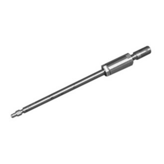
1.1 Overview The T9 ultrasonic flow transducer is used exclusively with the GE line of ultrasonic flowmeters. These transducers measure the flow rate of saturated steam and most gases through pipes having diameters between 2 in. (50 mm) and 48 in. - Page 10 Chapter 1. Information [no content intended for this page] Model T9 Ultrasonic Flow Transducer Installation Guide...
-
Page 11: Chapter 2. Installing Pipe Nozzles
2.1 Introduction Before the T9 transducers can be installed into the pipe, you will need to install pipe nozzles. Nozzles can be installed on a hot or cold pipe using a GE Nozzle Installation Kit. Nozzles are installed in a Tilted 45 configuration. -
Page 12: Identifying And Checking The Nozzle Installation Kit Components
IMPORTANT: You will need to supply eight in. 4.25 in. studs with two nuts each. Nozzle Side Welding Boss Side Threaded Rod with Washer and Nut Figure 2: Components for Nozzle Installation Kit Model T9 Ultrasonic Flow Transducer Installation Guide... -
Page 13: Selecting And Marking The First Nozzle Location
Flow 2. We recommend that you install the nozzles on a diameter as near as possible to the horizontal plane (i.e., 3 o’clock and 9 o’clock) as shown below. End View Model T9 Ultrasonic Flow Transducer Installation Guide... - Page 14 Side View 4. Spray this area with a marking dye product. Using a metal edge, scribe a vertical and a horizontal line (6 in. long) that intersect at the center punch mark. Side View Model T9 Ultrasonic Flow Transducer Installation Guide...
-
Page 15: Determining And Marking The Second Nozzle Location
Ensure that the sides of the film are cut parallel to each other. • Width - equal to the average outside diameter calculated in Step 1 above. • Length - equal to 4 times the outside diameter of the pipe. Average O.D. 4 X O.D. Model T9 Ultrasonic Flow Transducer Installation Guide... - Page 16 5. Remove the strip of film and fold it as shown below to determine the position which is diametrically opposite the overlap position when the film is reapplied to the pipe. Overlap Mark Fold to Here 6. Mark the outside of the fold for reference. Mark the Edge Model T9 Ultrasonic Flow Transducer Installation Guide...
- Page 17 Center punch this location prior to removing the strip of film. Punch Here Side View 9. Remove the film. 10. Scribe vertical and horizontal lines (each 6 in. long) to intersect at the center-punch mark. Scribe Lines Side View Model T9 Ultrasonic Flow Transducer Installation Guide...
-
Page 18: Installing The First Welding Boss
2. Scribe the oblique center line on the pipe at the prescribed distance from the true center line. The oblique center line should be marked on the side of the true center line that is closer to the second nozzle location. Oblique Center Line True Center Line Side View Model T9 Ultrasonic Flow Transducer Installation Guide... - Page 19 6. Remove the clamp and check the alignment again. If the boss is misaligned by 0.02 in. (0.5 mm) or more, remove the boss, grind off the welds and reinstall. Model T9 Ultrasonic Flow Transducer Installation Guide...
-
Page 20: Installing The First Nozzle
Welded Boss 2. Insert the pipe section of the jig into the pipe section of the nozzle and fasten using four studs and eight nuts (not supplied). Studs & Sets of Nuts Nozzle Model T9 Ultrasonic Flow Transducer Installation Guide... - Page 21 Jig/Nozzle Assembly Threaded Rod Welded Boss 4. Align the nozzle scribe marks with the pipe scribe marks and tighten the assembly in place, using the washer and nut. Washer and Nut Model T9 Ultrasonic Flow Transducer Installation Guide...
-
Page 22: Installing The Second Welding Boss And Nozzle
2. Hot tap holes in the pipe using hot tap machine equipped with a 3/4 in. (19 mm) drill bit. Then use a coupon retaining hole saw to cut a hole a minimum diameter of 2.36 in. (60 mm). Model T9 Ultrasonic Flow Transducer Installation Guide... -
Page 23: Chapter 3. Inserting T9 Transducers Into The Pipe
3.1 Introduction The T9 transducer is typically installed into a meter body. The meter body is a section of pipe that contains the ports where the transducers will be mounted. The meter body may be prefabricated or created by installing ports on the existing pipe. - Page 24 Chapter 3. Inserting T9 Transducers into the Pipe Inserting Transducers with the Simple Holder (cont.) 2. Insert the holder into the pipe nozzle. Place a spiral-wound gasket between the nozzle and the holder. The nozzle length determines the transducer face position.
- Page 25 Chapter 3. Inserting T9 Transducers into the Pipe Inserting Transducers with the Simple Holder (cont.) 4. Install the junction box on the end of the transducer using the compression fitting. Junction Box Compression Fitting 5. Repeat the above steps for the other transducer. The figure below shows a completed installation.
- Page 26 Chapter 3. Inserting T9 Transducers into the Pipe Inserting Transducers with the Simple Holder (cont.) 6. Use the equation below to calculate the path length (P) based on the pipe inside diameter and transducer face angle: P = ID/cos (A)
-
Page 27: Inserting Transducers With The Barrel Holder
Chapter 3. Inserting T9 Transducers into the Pipe 3.3 Inserting Transducers with the Barrel Holder A barrel holder is a flange with a pipe welded through its center (the flange and pipe size are dependent upon the application.) The pipe provides support for the transducer. Compression fittings on the top and bottom of the barrel holder keep the transducer in place. - Page 28 Chapter 3. Inserting T9 Transducers into the Pipe Inserting Transducers with the Barrel Holder (cont.) Procedure for Inserting Transducers with the Barrel Holder (cont.) 2. Insert the holder into the pipe nozzle. Place a spiral-wound gasket between the nozzle and the holder. The nozzle length determines the transducer face position.
- Page 29 Chapter 3. Inserting T9 Transducers into the Pipe Inserting Transducers with the Barrel Holder (cont.) 4. Install the junction box on the end of the transducer using the compression fitting. Junction Box Compression Fitting 5. Repeat the above steps for the other transducer.
-
Page 30: Inserting Transducers With The Flanged Holder
The flange has a large hub that supports the T9 transducer and also provides acoustic isolation. The transducer is inserted through the flange and is held in place by a 1/2 in. tube compression fitting. See Figure 4. - Page 31 Chapter 3. Inserting T9 Transducers into the Pipe Inserting Transducers with the Flanged Holder (cont.) 3. Tighten the compression fitting to hold the transducer in place. 4. Place a spiral-wound gasket over the end of the transducer. Note: You must use a gasket in order to provide the proper acoustic isolation.
- Page 32 Chapter 3. Inserting T9 Transducers into the Pipe Inserting Transducers with the Flanged Holder (cont.) 3.4.1 Securing the Transducers 1. Secure the flanges together by placing the studs, washers and nuts as shown below. Hand-tighten each stud. The factory recommends using ASTM A193 Grade B7 (or equivalent) studs and ASTM A19 Grade 2H (or equivalent) nuts.
-
Page 33: Securing The Transducers
Chapter 3. Inserting T9 Transducers into the Pipe 3.4.1 Securing the Transducers (cont.) 2. Once all the studs are inserted and hand-tightened, the studs must be torqued to 80 ft-lb (108 N-m) in three stages. Set the torque wrench to 30 ft-lb (40 N-m) and torque the studs in the order shown below. - Page 34 Chapter 3. Inserting T9 Transducers into the Pipe 3.4.1 Securing the Transducers (cont.) 6. Install the junction boxes on the end of the transducers using the compression fittings. Compression Fitting Top View 7. Refer to your flowmeter Startup Guide or User’s Manual to make transducer electrical connections.
-
Page 35: Chapter 4. Maintenance
Chapter 4. Maintenance 4.1 Introduction Once the transducers are properly installed into the pipe nozzles as described in the previous section, the T9 transducers require no additional adjustments. Periodic inspection of the installation to verify the torque on the mounting bolts may be required, if erratic flow rate measurements are observed. - Page 36 Chapter 4. Maintenance Removing Transducers (cont.) 3. Disconnect the transducer cables at the junction box. Junction Box Model T9 Ultrasonic Flow Transducer Installation Guide...
- Page 37 Chapter 4. Maintenance Removing Transducers (cont.) 4. Remove the junction box from the end of the transducer by loosening the compression fitting and unscrewing the junction box. Compression Fitting Model T9 Ultrasonic Flow Transducer Installation Guide...
- Page 38 Bolts Gasket Blind Flange 7. Repeat steps 3 through 6 for the other transducer if necessary. You have completed the removal procedure, it is now safe to reopen the process line. Model T9 Ultrasonic Flow Transducer Installation Guide...
-
Page 39: Chapter 5. T9 Specifications
Europe: -40 to +158°F (-40 to +70°C) Ambient Temperature Range North America: -4 to +140°F (-20 to +60°C) Normal Temperature: -58 to +302°F (-50 to +150°C) Process Temperature Range High Temperature: -58 to +500°F (-50 to +260°C) Model T9 Ultrasonic Flow Transducer Installation Guide... - Page 40 Chapter 5. T9 Specifications [no content intended for this page] Model T9 Ultrasonic Flow Transducer Installation Guide...
- Page 41 AUTHORIZATION NUMBER (RAN), and shipping instructions for the return of the instrument to a service center will be provided. 2. If GE Sensing instructs you to send your instrument to a service center, it must be shipped prepaid to the authorized repair station indicated in the shipping instructions.
- Page 42 Warranty [no content intended for this page] Model T9 Ultrasonic Flow Transducer Installation Guide...
- Page 44 Customer Support Centers U.S.A. The Boston Center 1100 Technology Park Drive Billerica, MA 01821 U.S.A. Tel: 800 833 9438 (toll-free) 978 437 1000 E-mail: sensing@ge.com Ireland Sensing House Shannon Free Zone East Shannon, County Clare Ireland Tel: +353 (0)61 470291 E-mail: gesensingsnnservices@ge.com An ISO 9001:2000 Certified Company www.gesensinginspection.com/en/about_us/quality.html...