Table of Contents
Advertisement
SERVICE
INDUCTION HOB
INDUCTION HOB
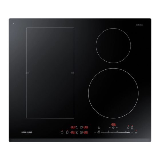
NZ64K5747BK
INDUCTION HOB
BASIC
: NZ63K7777BK
MODEL
: NZ64K5747BK
MODEL CODE : NZ64K5747BK/EF
Manual
CONTENTS
1. Precaution
2. Product Specification
3. Disassembly and Reassembly
4. Troubleshooting
5. PCB Diagrams
6. Wiring Diagrams
NZ64K5747BK/EU
NZ64K5747BK/EO
NZ64K5747BK/EE
NZ64K5747BK/WT
NZ64K5747BK/ET
Advertisement
Table of Contents

Related Manuals for Samsung NZ63K7777BK


Summary of Contents for Samsung NZ63K7777BK
- Page 1 INDUCTION HOB BASIC : NZ63K7777BK MODEL : NZ64K5747BK MODEL CODE : NZ64K5747BK/EF NZ64K5747BK/EU NZ64K5747BK/EO NZ64K5747BK/EE NZ64K5747BK/WT NZ64K5747BK/ET SERVICE Manual INDUCTION HOB INDUCTION HOB CONTENTS 1. Precaution 2. Product Specification 3. Disassembly and Reassembly 4. Troubleshooting 5. PCB Diagrams 6. Wiring Diagrams...
-
Page 2: Table Of Contents
Contents Contents 1. General Safety Precautions..............1 2. -
Page 3: General Safety Precautions
This document can not be used without Samsung’s authorization. 1. General Safety Precautions 1. Information contained in this manual is intended for 8. The hob is to be connected to the mains using a use by a qualified service technician. The technician... -
Page 4: Specifications
This document can not be used without Samsung’s authorization. 2. Specifications 2-1 Induction Heating • The Principle of Induction Heating: When you place your cookware on a cooking zone and you turn it on, the electronic circuits in your induction hob produce “induced currents” in the bottom of the cookware which instantly raise cookware’s temperature. -
Page 5: Table Of Specification
This document can not be used without Samsung’s authorization. 2. Specifications Basic Model New Model Model Name NZ63J9770EK NZ64K5747BK Control Features Sound on/off Headen Lock Power Level 1~15 level 1~15 level Kichen Timer Timer Alarm Power Control 15+Booster 15+Booster Direct Access... -
Page 6: Accessory
This document can not be used without Samsung’s authorization. 2-4 Accessory Bracket Spring - 4 -... -
Page 7: Installing The Hob
This document can not be used without Samsung’s authorization. 2-5 Installing the hob 2-5-1 Installing into the countertop NOTE Make a note of the serial number on the appliance rating label prior to installation. This number will be required in the case... - Page 8 This document can not be used without Samsung’s authorization. 2-5 Installing the hob Explanation Size Distance between wall and Induction Min 40 mm Size of depth of Induction 520 mm Distance between Induction and end of table Min 40 mm...
- Page 9 This document can not be used without Samsung’s authorization. 2-5 Installing the hob - 7 -...
-
Page 10: Disassembly And Reassembly
This document can not be used without Samsung’s authorization. 3. Disassembly and Reassembly 3-1 Tools for Removal and Reassembly Tool 1. Tool : Longnose 2. Remarks : PBA hook 1. Tool : Driver 2. Type : ( + ) 3. Remarks : SCREW... -
Page 11: Replacement Of The Assy Top Plate
This document can not be used without Samsung’s authorization. 3-2 Replacement of the Assy Top Plate Attention The Ceramic Glass may break if you use force especially on the edge. Parts Explanation Photo Explanation 1. Disconnect power. 2. Remove 4 - side direction 16 Screws securing the Assy Top Plate to the Assy Case Burner. -
Page 12: Replacement Of The Working Coil
This document can not be used without Samsung’s authorization. 3-4 Replacement of the Working Coil Explanation Photo COIL WORKING 145 COIL WORKING FLEX COIL WORKING 210 Parts Explanation Photo Explanation Working Coil 1. Bend the Cover-Coil a little. - 10 -... - Page 13 This document can not be used without Samsung’s authorization. 3-4 Replacement of the Working Coil Parts Explanation Photo Explanation 2. Remove Screws securing the Working-Coil 3. Disconnect all lead wires from the Assy-Working Coil. Working Coil 4. For the replacement of Sensor-Top, pull &...
-
Page 14: Replacement Of The Pba
This document can not be used without Samsung’s authorization. 3-5 Replacement of the PBA Parts Explanation Photo Explanation 1. Remove all screws securing the CASE-INDUCTION. 2. Disconnect all wires from the WORKING-COIL. 3. Remove the CASE-INDUCTION. 4. Disconnect all wires from the PBA. - Page 15 This document can not be used without Samsung’s authorization. 3-5 Replacement of the PBA Parts Explanation Photo Explanation 5. Remove all screws securing the PBA. 6. The PBA is fixed in place by a series of hooks. Remove these using a tool Then remove the PBA.
-
Page 16: Replacement Of The Power Cable
This document can not be used without Samsung’s authorization. 3-6 Replacement of the POWER CABLE Parts Explanation Photo Explanation 1. Remove screws securing the GND WIRE and HOLDER-CABLE. 2. Remove locking holder. Power Cable 3. Pull the POWER CABLE outwards to remove it from the socket. -
Page 17: Troubleshooting
This document can not be used without Samsung’s authorization. 4. Troubleshooting 4-1 Part Checking method Parts Photo Good No Good 20˚C : 292.9kΩ SENSOR TEMP 40˚C : 118.7kΩ The others (DG32-00015A) 60˚C : 52.76kΩ 80˚C : 25.38kΩ 20˚C : 57.9KΩ ~ 65.5KΩ... -
Page 18: Demo Mode
This document can not be used without Samsung’s authorization. 4-2 DEMO mode This mode is for Shop display. At this mode, user can only operate touch key button without burner power on. 1. Touch Lock key for 3 seconds. 2. Touch Timer key for 3 seconds. An acoustic signal will sound. -
Page 19: Failure Codes
This document can not be used without Samsung’s authorization. 4-3 Failure Codes 4-3-1 Temp Sensor Information Information Solution Page Code Top Sensor Open Information (Sensor-Top) It occurs due to a defective sensor, misplaced wires, a defective PCB and 18 Page when A/D value that MICOM senses rises over 252. - Page 20 This document can not be used without Samsung’s authorization. 4-3-3 Top Sensor Open Information ( Connect the sensor. Is the sensor connected? : check if the sensor wire is damaged, Replace the wire. if the sensor housing is inserted into the connector of the PCB.
- Page 21 This document can not be used without Samsung’s authorization. 4-3-4 Top Sensor Short Information ( Remove any foreign substance Is the sensor terminal part : check if the sensor is slightly shorted. from the shorted part. of the PCB shorted?
- Page 22 This document can not be used without Samsung’s authorization. 4-3-5 IGBT Sensor Open Information( Is the sub wire connected? : check if the sub wire is damaged Connect the sub wire. (from Assy-Inverter Module to if the housing is inserted into the Assy Touch PCB) connector of the PCB.
- Page 23 This document can not be used without Samsung’s authorization. 4-3-6 IGBT Sensor Short Information ( Is the sub wire connected? : check if the sub wire is damaged Connect the sub wire. (from Assy-Inverter Module to if the housing is inserted into the Assy Touch PCB) connector of the PCB.
- Page 24 This document can not be used without Samsung’s authorization. 4-3-7 Key Short Information ( Is the key not recognized at all? Is the key recognized intermittently? Is the key not recognized after cleaning the control panel? Assy Touch PCB is...
- Page 25 This document can not be used without Samsung’s authorization. 4-3-8 Touch key data Information ( After connect plug, does the symptom continue? Touch PCB is interrupted Replace the Touch PCB. due to some electrical noise. Perform the operation again and check if it is working properly.
- Page 26 This document can not be used without Samsung’s authorization. 4-3-9 Over Temperature Information ( Is the hob operated with Make the hob be cool empty cookware? (Ceramic glass's surface) Is the Top sensor wire Connect the wire connected properly by burner position? properly.
- Page 27 This document can not be used without Samsung’s authorization. 4-3-10 Pan Detection Information ( Is the hob operated with Place the cookware no cookware? Is the hob operated with Place the suitable un-suitable cookware? cookware (small size, aluminium, etc) S/W Information After Power ->...
- Page 28 This document can not be used without Samsung’s authorization. 4-3-11 DC Motor Locking Information ( Connect the Motor wire. Is the Motor wire connected? Remove the Is there some interference at rotor interference at Motor. or blade of Motor? S/W Information After Power ->...
- Page 29 This document can not be used without Samsung’s authorization. 4-3-12 Commnunication information ( Is the wire connected properly? Connect wire propely Is the Main PCB or Sub PCB Update to S/W S/W check properly? Replace the Main PCB and Sub PCB Perform the operation again and check if it is working properly.
-
Page 30: Electrical Malfunction
This document can not be used without Samsung’s authorization. 4-4 Electrical Malfunction Troubleshooting (Power) No Power Check the circuit breaker. Check terminal block voltage. Check the terminal block connections (220V~240V, 50/60Hz) Replace or Repair the wiring Check the wiring. Check the votage of PCB, SMPS... - Page 31 This document can not be used without Samsung’s authorization. 4-4 Electrical Malfunction Troubleshooting (PCB failure) PCB Failure - Check the input voltage of Repair Faulty wiring - Check Terminal block PCB SMPS (input check- or PCB check voltage(220V~240V). point : 220V~240V ) Reset the circuit braker or check main power.
-
Page 32: Auto Function Check Test
This document can not be used without Samsung’s authorization. 4-5 Auto Function Check Test Induction Hob can do self check test. If product have some problem, test program will be stopped and display the corresponding information code. Auto Function Check... -
Page 33: Diagrams
This document can not be used without Samsung’s authorization. 5. P.C.B Diagrams 5-1 P.C.B Diagrams : Touch (Control) PCB ( This Document can not be used without Samsung’s authorization ) Parts Number Part Name Function and Role Inverter PBA wire connector... -
Page 34: Diagrams : Smps Pcb
This document can not be used without Samsung’s authorization. 5. P.C.B Diagrams 5-2 P.C.B Diagrams : SMPS PCB ( This Document can not be used without Samsung’s authorization ) Parts Number Part Name Function and Role CON01 AC Input connector... -
Page 35: Diagrams : Inverter Pcb
This document can not be used without Samsung’s authorization. 5. P.C.B Diagrams 5-3 P.C.B Diagrams : Inverter PCB ( This Document can not be used without Samsung’s authorization ) Parts Number Part Name Function and Role Bridge Diode IC Bridge Diode IC... -
Page 36: Wiring Diagrams
This document can not be used without Samsung’s authorization. 6. Wiring Diagrams ( This Document can not be used without Samsung’s authorization ) - 35 -... - Page 37 North & Latin America gspn3.samsungcsportal.com China china.samsungportal.com This Service Manual is a property of Samsung Electronics Co.,Ltd. © Samsung Electronics Co., Ltd. March. Any unauthorized use of Manual can be punished under applicable 2016 Printed in Korea International and/or domestic law.