Table of Contents
Advertisement
Advertisement
Table of Contents

Related Manuals for Honeywell FSL100-IR3


Summary of Contents for Honeywell FSL100-IR3
- Page 1 TECHNICAL HANDBOOK FSL100 SERIES FLAME DETECTORS AND ACCESSORIES...
- Page 2 Revision History Revision Comment Date Issue 01 First Issue 29/07/2015 Issue 02 First Revision 02/09/2016 Issue 03...
- Page 3 Disclaimer In no event shall Honeywell be liable for any damages or injury of any nature or kind, no matter how caused, that arise from the use of the equipment referred to in this manual. Strict compliance with the safety procedures set out and referred to in this manual, and extreme care in the use of the equipment, are essential to avoid or minimise the chance of personal injury or damage to the equipment.
- Page 4 This page deliberately left blank.
-
Page 5: Table Of Contents
CONTENTS Contents Introduction .................................... 3 Intended Readers ................................3 Safety Hazards, Warnings and Cautions ..........................5 General Warnings and Cautions ............................5 Important Information ................................ 5 FSL100 Safety Features ..............................6 Overview ....................................7 Mechanical Installation ................................9 Siting ....................................9 Mounting and Orientation .............................. - Page 6 CONTENTS How to Install the Detector Using the Swivel Mounting ....................29 Cleaning ..................................30 FSL100-TL Test Lamp Non-EX ............................. 31 10.1 Safety Instructions ................................31 10.2 Before First Use ................................32 10.3 Test Lamp Operation ..............................32 10.4 Battery Charging and Storage: ............................32 10.5 Bulb Replacement ................................
-
Page 7: Introduction
This Manual should be read by everyone who operates or monitors the FSL100 Flame Detection system. Only personnel who have been fully trained by Honeywell are authorised to Install, Set-up, Service, and Test, Repair, or Recondition Honeywell flame detection systems. - Page 8 INTRODUCTION This page deliberately left blank. MAN0987_Iss 2_09/16 FSL100 Series Flame Detectors Technical Handbook...
-
Page 9: Safety Hazards, Warnings And Cautions
This manual is for use with FS100 Series Fire Detectors only. Honeywell Analytics can take no responsibility for installation and/or use of its equipment if not done so in accordance with the appropriate issue and/or amendment of the Operating Manual. -
Page 10: Fsl100 Safety Features
Every effort has been made to ensure the accuracy of this document; however, Honeywell Analytics can assume no responsibility for any errors or omissions in this document or their consequences. Honeywell Analytics would greatly appreciate being informed of any errors or omissions that may be found in the content of this document. -
Page 11: Overview
For example, plain glass and acrylic are known to block IR but may transmit UV, whereas coated materials may block both. Please consult Honeywell Analytics Technical Support for further information if you need this type of application MAN0987_Iss 2_09/16... - Page 12 OVERVIEW This page deliberately left blank. MAN0987_Iss 2_09/16 FSL100 Series Flame Detectors Technical Handbook...
-
Page 13: Mechanical Installation
Remember that the FSL100 series are flame detectors only; they cannot detect flammable gas or dust atmospheres. Please contact Honeywell Analytics if you need a flammable atmosphere detection system. Generally speaking, one or more FSL100 flame detectors should be positioned on walls or posts above the monitored object or area, and they should overlap so that shadow areas cannot occur (see diagrams that follow). -
Page 14: Cone Of Vision
INSTALLATION 4.4 Cone of Vision The FSL100 flame detector has a cone of vision of 90° so it can monitor an area extending from floor to ceiling and extending to approximately 23 m (FSL100-UV and UVIR) or 35 m (FLS100-IR3). Figure 3. -
Page 15: Mounting Below A Ceiling
To avoid the risk of smoke blocking their fields of view, you should mount the FSL100-IR3 flame detectors at least 0.5 m (2 ft), and the FSL100-UV and FSL100-UVIR detectors at least 1.5m (6 ft), below the ceiling (see dimension ‘D’... -
Page 16: Vote Count
INSTALLATION 4.7 Vote Count FSL100 flame detectors will not give an alarm until several different alarm criteria occur at the same time, and the probability of a false alarm is very low. The flame detector is therefore suitable for relay activated actions (i.e. drenching) based on the signal of one flame detector. -
Page 17: Weather Protection
INSTALLATION 4.8 Weather Protection It is recommended to place a hood or shield above the flame detector to protect it from sunlight, rain and snow. A stainless steel metal plate of approximately 30 x 30 cm (12 x 12 in) can be mounted directly above the flame detector without inhibiting its field of view. - Page 18 INSTALLATION This page deliberately left blank. MAN0987_Iss 2_09/16 FSL100 Series Flame Detectors Technical Handbook...
-
Page 19: Electrical Installation
INSTALLATION 5 Electrical Installation 5.1 Power Supply Typical Cable Data Maximum Cable Length (L) Cable size Cable resistance Metres Feet Ω/km (Ω/mile) (cross sectional area) ≅ 20 AWG 36.8 (59.2) 0.5 mm ≅ 17 AWG 19.5 (31.4) 1516 1.0 mm ≅... -
Page 20: Wiring Diagram
INSTALLATION 5.4 Wiring Diagram Terminal 1 has a Blocking Diode for reverse polarity protection and a Multi-fuse for overcurrent protection. FSL100 Wiring Diagram (Power On – Normal) Figure 9. Terminal Input Terminal Input +10 to +28 VDC Input NC Alarm –Ve Input NC Fault Not in use... -
Page 21: Electrical Connection (General)
INSTALLATION 5.5 Electrical Connection (General) The flame detector has several wiring options; the most important are: Wiring to a fire control panel using the ‘current increase’ principle. Wiring to a PLC using a 0-20 mA output. Wiring with an additional manual self-test. Stand-alone wiring, with direct use of relays. -
Page 22: Wiring To A Fire Control Panel
INSTALLATION 5.7 Wiring to a Fire Control Panel The flame detector can be connected to a fire control panel using the current increase principle. The flame detector is connected to the fire panel with 3 or 4 core cables, i.e. 2 cores for the power supply and 1 or 2 cores for the loop. -
Page 23: Wiring To A Plc
INSTALLATION 5.8 Wiring to a PLC R = max 500Ω at 24 VDC Screen end Screen end isolated from connected to detector and system earth earth (ground) (ground) Figure 12. Wiring to a PLC Notes 0-20 mA sinking analogue output, non-isolated. 5.9 Wiring to a 4-20 mA Non-Isolated (Sourcing) Current Output The FLS100 detectors can be wired to a 4-20 mA non-Isolated (Sourcing) Output by using the controller’s alarm and fault relays, as shown below. -
Page 24: Connecting The Manual Self-Test
INSTALLATION 5.10 Connecting the Manual Self-Test A manual self-test switch can be incorporated by supplying a +10 to +28 VDC switched current to terminal 14 in the detector. This switch can be integral or external to the Fire Control panel or the PLC. Figure 14. -
Page 25: Commissioning And Testing
6 Commissioning and Testing Notes: Commissioning, maintenance and functional testing of Honeywell Fire Detection systems must only be carried out by qualified Honeywell approved persons or qualified persons trained in accordance with this manual. All local laws and regulations for the commissioning and the cabling apply, including law and regulations for activating alarm systems, extinguishing systems and other outputs. -
Page 26: Functional Testing
FSL100 window prior to testing. Contamination lowers the sensitivity of the flame detector and can build up over time if not monitored and cleaned regularly. Honeywell supplies the FSL100-TL (safe area) and FSL100-TLX (hazardous area) test lamps for the FSL100 series of flame detectors. Please read the test lamp instructions in this manual before you start the functional test. -
Page 27: Fault Testing
COMMISSIONING 6.4 Fault Testing Caution Always ensure that relay operated outputs and alarms are inhibited or isolated before carrying out any work on Alarm systems. Always ensure that Alarm Systems are returned to Normal Operation when work is completed. Refer to the manufacturer’s instructions before carrying out any testing as some controllers require sensors to be decommissioned before removal or replacement. - Page 28 COMMISSIONING This page deliberately left blank. MAN0987_Iss 2_09/16 FSL100 Series Flame Detectors Technical Handbook...
-
Page 29: Fsl100 Operation
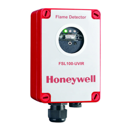
OPERATION 7 FSL100 Operation 7.1 The Display LEDs The FSL100 series flame detectors have 3 LEDs on the display: Steady green: powered up and in normal operation Steady yellow: fault (blinking yellow: repeated self-test after a self-test fault) ... -
Page 30: Manual Self-Test
OPERATION 7.7 Manual Self-Test The flame detector can test the sensor(s) and also the signal processing with help of the optional manual self-test circuit. During a successful manual self-test the alarm relay is energized and the red alarm LED illuminates. If the detector is latched, the alarm continues until the detector is powered off. -
Page 31: Maintenance
In hazardous areas use only a clean, damp cloth (moistened with water) to clean the mounting and detector. FSL100 has no user serviceable parts. Honeywell Analytics recommends that the unit is checked and serviced annually by an approved Honeywell field technician. - Page 32 MAINTENANCE This page deliberately left blank. MAN0987_Iss 2_09/16 FSL100 Series Flame Detectors Technical Handbook...
-
Page 33: Fsl100-Sm21 Swivel Mount
Note: The sensors should be clearly visible through the detector window. Adjust the detector to the correct orientation and fully tighten the two swivel bolts. Check that all is secure and correctly fitted, and then test (with a Honeywell approved test lamp) to ensure that the operation is correct. -
Page 34: Cleaning
ACCESSORIES Wall Plate Detector Plate Figure 17. SM21 Swivel Mount Attachment Plate Dimensions 9.2 Cleaning Only experience of the operating environment will dictate how often you clean your detectors and mountings, but you should remove contamination by wiping the mounting, detector and detector window regularly with a lightly dampened micro-fibre cloth. Do not use dry cloth or dry paper in flammable atmospheres as this may cause static discharge that may result in an explosion. -
Page 35: Fsl100-Tl Test Lamp Non-Ex
The FSL100-TL (test lamp) is a rechargeable, hand-held IR and UV radiation source that is specifically designed to test Honeywell FSL100 series flame detectors used in safe areas only. The detection range is approximately 4 meters (13 ft). It is supplied in a custom carry case with a dedicated charging unit suitable for mains connection. -
Page 36: Before First Use
ACCESSORIES Caution – WEEE Directive According to local laws and regulations batteries should be disposed of separately from household waste. Take them to a collection point designated by local authorities when they are no longer needed. 10.2 Before First Use The battery is fully charged when leaving the factory, but it should be fitted to the lamp and recharged prior to use. -
Page 37: Bulb Replacement
In the event of a bulb failure, you may replace the bulb with Honeywell part number FSL100-TLBU only. However, Honeywell recommend that this is only carried out by competent personnel, or that the Test Lamp is returned to Honeywell for repair. - Page 38 ACCESSORIES This page deliberately left blank. MAN0987_Iss 2_09/16 FSL100 Series Flame Detectors Technical Handbook...
- Page 39 ACCESSORIES This page deliberately left blank. MAN0987_Iss 2_09/16 FSL100 Series Flame Detectors Technical Handbook...
-
Page 40: Fsl100-Tlx Test Lamp Hazardous Areas
The test lamp is only approved for testing Honeywell FSL100 flame detectors. Do not use the test lamp in wet conditions. The lamp does not contain any user replaceable parts other than the batteries. In the event of faults contact Honeywell Analytics Technical Support for help. -
Page 41: Before First Use
ACCESSORIES 11.2 Before First Use Perform the following actions in a known safe area: Remove the two screws securing the battery compartment cover. Remove the battery cover. Place the four supplied AA batteries correctly in the battery compartment. Replace the battery compartment lid and secure with the 2 screws. Do not overtighten. Place the test lamp in its protective case with the shoulder strap in its correct position. -
Page 42: Fsl100 Specifications
2 mA optical fault Current Output 4 mA normal operation 20 mA Alarm Maximum Range (IR) 35 m/115 ft. (FSL100-IR3) (to alarm <10 s for a 0.1 m n-heptane fire) Maximum Range (UV and UVIR) 23 m/75 ft. (FSL100-UV and FSL100-UVIR) (to alarm <10 s for a 0.09 m... - Page 43 FM3260 Approval FSL100-UV Flame Detector FSL100-UVIR Flame Detector FSL100-IR3 Flame Detector: Non-Incendive, Class 1,2 & 3 Div 2 FM3611 Approval FSL100-UV Flame Detector: Non-Incendive, Class 1,2 & 3 Div 2 FSL100-UVIR Flame Detector: Non-Incendive, Class 1,2 & 3 Div 2...
-
Page 44: Accessory Specifications
SPECIFICATIONS CERTIFICATION 13 Accessory Specifications FSL100-TL Safe Area Test Lamp Specifications Lamp Housing ABS (plastic) black Ingress Protection rating IP30 / NEMA 1 Adapter (charger) 100-240 Vac, 500 mA switching with plugs for US, EU, GB and AU Battery 12 VDC / 2.8 Ah Sealed Lead Acid Battery Lamp H3, 12 VDC / 100 W +4 to +40 ºC (+39 to +104 ºF) - Page 45 SPECIFICATIONS CERTIFICATION This page deliberately left blank. MAN0987_Iss 2_09/16 FSL100 Series Flame Detectors Technical Handbook...
-
Page 46: Fsl100 Certifications
14 FSL100 Certifications 14.1 EC Declaration of Conformity A full EC declaration of conformity is available on either original hardcopy or electronic file (Honeywell Analytics website). This document lists the European Standards with which FSL100 Series flame detectors comply. 14.2 National and International Certificates of Compliance... -
Page 47: North American Approvals - Cfmus Class 3611 & Fm Class 3260
FSL100-UV UV Flame Detector FSL100-UVIR UVIR Flame Detector FSL100-IR3 IR3 Flame Detector Nonincendive per FM class 3611: Class I, II, III, Div. 2, Groups A, B, C, D, F, G Nonincendive per C22.2 No. 213: Class I, Div. 2, Groups A, B, C, D Dust-tight per C22.2 No. - Page 48 Performance per FM class 3260:2000 Operating temperature : -40 ºC to +70 ºC Response characteristics Fuel FSL100-UV FSL100-UVIR FSL100-IR3 time n-Heptane 30 x 30 cm (1 sqft) 23 m (75 ft) 23 m (75 ft) 35 m (115 ft) within 10 sec.
- Page 49 CERTIFICATION MAN0987_Iss 2_09/16 FSL100 Series Flame Detectors Technical Handbook...
-
Page 50: Ordering Information
FSL100-UVIR-W Same specification as UVIR; white body Triple IR flame detector suitable for: ATEX zone 2/22 FM3611 Class 1, 2 and 3, Div 2 FSL100-IR3 EN54-10 certificate FM3260 approval FSL100-IR3-W Same specification as IR3; white body... - Page 51 ORDERING This page deliberately left blank. MAN0987_Iss 2_09/16 FSL100 Series Flame Detectors Technical Handbook...
-
Page 52: Returns And Repairs Policy
16 Returns and Repairs Policy Please contact Honeywell Analytics Technical Support if you want to make a claim under the warranty terms, or if you want to arrange a test, repair or replacement outside of warranty, or if you want to return any unused item. Contact details are on the back page of this handbook. - Page 53 RETURNS This page deliberately left blank. MAN0987_Iss 2_09/16 FSL100 Series Flame Detectors Technical Handbook...
-
Page 54: List Of Figures
FIGURES 17 List of Figures Figure 1. Comparison of Visible Radiation Range to UV/IR Radiation Range Figure 2. Mounting Hole Dimensions Figure 3. Cone of View Figure 4. Shadow Effect Figure 6. Shadow Cancelling Figure 7. Mounting Clearance Figure 8. Voting Arrangement Using Four Detectors FSL100 Wiring Diagram (Power On –... - Page 55 FIGURES This page deliberately left blank. MAN0987_Iss 2_09/16 FSL100 Series Flame Detectors Technical Handbook...
-
Page 56: List Of Tables
TABLES 18 List of Tables Table 1. FSL100 Cable Data Table 2. FSL100 Terminal Allocation Table 3. Accessory Specifications Table 4. Ordering Information MAN0987_Iss 2_09/16 FSL100 Series Flame Detectors Technical Handbook... - Page 57 Tel: +82 2 6909 0300 intended to form the basis of a contract VOIP: +8 5401 0321 Fax: +82 2 6909 0329 India Tel: +91 124 4752700 analytics.ap@honeywell.com Technical Services EMEA: HAexpert@honeywell.com ha.us.service@honeywell.com ha.ap.service@honeywell.com Issue 2_09/2016 H_MAN0987_EMEA www.honeywell.com 2055M1000_ECO A04880 © 2016 Honeywell Analytics...