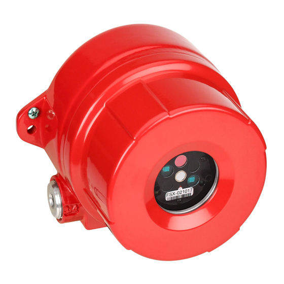
Honeywell FS24X Installation Manual And Operating Manual
Fsx fire and flame detectors
Hide thumbs
Also See for FS24X:
- User manual (17 pages) ,
- User manual (36 pages) ,
- Quick reference manual (2 pages)

Related Manuals for Honeywell FS24X


Summary of Contents for Honeywell FS24X
- Page 1 Installation Guide and Operating – Manual FSX™ Fire and Flame Detectors Model FS24X™ FS24X QuadBand Triple IR™ Multi-Spectrum Infrared Electro-Optical Multi-Spectral Digital WideBand IR Sensor Radiant Energy Fire and Flame Detector...
- Page 2 This manual is subject to change without notice. Copyright 2015 by Honeywell International Inc. While this information is presented in good faith and believed to be accurate, Honeywell disclaims the implied warranties of merchantability and fitness for a particular purpose and makes no express warranties except as may be stated in its written agreement with and for its customers.
-
Page 3: Table Of Contents
4.6.2 False Alarm Immunity .......................... 24 4.7 Drawings ................................. 25 4.7.1 Outline and Dimensions ........................25 4.7.2 Wiring and Terminal Connections ....................... 26 4.7.3 BRE Detector Labels ..........................28 4.7.4 EN54 Detector Label ..........................29 INDEX ..................................30 CONTACT HONEYWELL ANALYTICS ........................Honeywell... -
Page 4: Section 1: Introduction
The WideBand IR spectral radiant energy wavelengths sensed by the Quad (4) sensors span from approximately 0.4 to 5.5 microns for the FS24X. The Model FS24X Multi-Spectrum Fire and Flame Detectors are designed and Factory Mutual approved for use in Class Div. -
Page 5: Mechanical Specifications
-67° F to +221° F (-55° C to +105° C) 1.2.4 Performance Specifications Field of View: FS24X detectors have a cone of view of 90° horizontal and 80° vertical with the highest sensitivity on the central axis Sensitivity: One (1) sq. ft. heptane reference fire at 200 feet... -
Page 6: Flame Performance Certification
Installation Guide and Operating Manual Flame Performance Certification (See Sections 4.7.3 and 4.7.4 on page 28 and 29) 1.2.6 Agency Standard Certificate Notes LPCB EN 54-10:2002 +A1:2005 1175a/02 Sensitivity settings: Very High, High EN 54-10:2002 +A1:2005 0832-CPR-F0516 EN 54-10 Class 1 Honeywell... -
Page 7: Features & Benefits
FSC Windows® based PC Interface User can perform remote FSX Detector diagnostics, real-time status, Real-Time Graphing (RTG), SnapShot data recording, and downloading FirePic’s with Honeywell Analytics’ exclusive FSIM-2 ® USB Interface Unit and easy to use Windows based PC Software. -
Page 8: Section 2: Installation
Detector’s field of view. 2. The installation shall take into account that the FS24X orientation should be with the base horizontal (see Figure 2-1) as the view angle in this direction is 90°. The vertical angle is 90°. - Page 9 Figure 2-5 CAUTION: Follow static protection procedures while handling the connectors and the wiring of the Module puck to the Detector. Use a wrist strap connected to earth ground. Honeywell...
-
Page 10: Opening The Detector
1. Loosen the set screw on the enclosure lid (see Figure 2-6). Figure 2-6 2. Turn counterclockwise (CCW) to unscrew the enclosure lid (see Figure 2-7). Figure 2-7 3. Loosen the three captive screws on the Detector Module puck (see Figure 2-8). Figure 2-8 Honeywell... -
Page 11: Detector Connections
Alarm COM 4-20mA Sink Figure 2-10 Fault NO Detector Puck, ( rear view Fault COM +24 VDC DC Return Contacts shown with no power applied Note: Do not attempt to open the Detector Module puck as this voids all warranties. Honeywell... - Page 12 Installation Guide and Operating Manual Figure 2-11 Recommended Wiring Configurations Honeywell...
-
Page 13: Installation Practices
, check that the Detector is configured correctly for the specific B efore completing the installation application. The FSX Detectors Factory Default Settings are: Alarm Relay Outputs are Non-Latching and Normally De-Energized SW2-1 OFF SW2-7 OFF Detector Range / Sensitivity is Medium (2) SW2-2 OFF SW2-3 ON Honeywell... -
Page 14: Start-Up And Commissioning
Note: Honeywell Analytics FSX Detectors feature an automatic built-in “through the lens” test that verifies the cleanliness of its viewing window lens and test its internal electronics and software. - Page 15 Remember to disable the outputs, as a full functional test includes activating the ALARM outputs. A Honeywell Analytics Test Lamp must be used for this test (Section 4.4). Point the Test Lamp directly at the front of the Detector (on axis as much as possible, within a distance of about 1 to 25 feet). Activate the Test Lamp by pressing and holding its pushbutton.
-
Page 16: Section 3: Operation
Infrared (IR) consists of spectral wavelengths longer than the color red. The IR range for fire detection, which is invisible to the human eye, is from about 700 nanometers to 7000 nanometers (0.7 to 7.0 microns). Honeywell Analytics’ FS24X Fire Detectors utilize a NearBand IR™ portion of the spectrum from approximately 185 to 260 nanometers and a WideBand IR portion from approximately 0.7 to 3.3 microns. - Page 17 Auxiliary Relay SW2-4 SW2-5 No Verify Time 5 Sec Verify Time During a fire, model FS24X-911-24-5 10 Sec Verify Time detectors will alarm in non-latching 20 Sec Verify Time mode and will unlatch when the fire decreases. If the condition persists...
-
Page 18: Led Status Indicators
Installation Guide and Operating Manual LED Status Indicators The Model FS24X Detector uses three (3) separate, bright LED’s to indicate the Detector’s status. The Green LED blinks (flashes) once every ten (10) seconds to indicate a Normal, safe operational condition (i.e. -
Page 19: Fault Conditions
Dirty Window Lens (Yellow LED flashes, the Yellow LED is ON [solid] for all other Faults). Maintenance After the FS24X Detector is installed and commissioned, there is little maintenance required. However, a complete “end-to-end” test of the entire fire detection system should be performed periodically depending on the application. -
Page 20: Section 4: Appendix
Honeywell Analytics warrants its Products against defects in material and workmanship under normal use and service for a period of three years from the date of shipment as described herein. Honeywell Analytics, at its option, will repair or replace, at no charge, such products found to be defective during the warranty period provided that they are returned in accordance with the terms of this warranty. -
Page 21: Product Variations
2 = Relays / HART Communication Application 1 = General Applications Manufacturer’s Code 2 = Standard Honeywell Analytics Detector - 110° Field of View (-1 has been replaced by -2) 9 = Standard Honeywell Analytics Detector - 90° Field of View EXAMPLES: FS24X-911-211 QuadBand Triple IR Detector, 90°... -
Page 22: Test Lamps
TL-2055 Test Lamp is as follows. If the FS24X set at Highest Sensitivity alarms to a fully charged TL-2055 Test Lamp at a distance between 1 and 25 feet, then the FS24X is in normal operating condition. -
Page 23: Field Of View Restrictor
EN54-10 standard. Additional Performance Specifications 4.6.1 Flame Response Sensitivity The following table provides FS24X typical INDOOR response times and distance to various fuels: FS24X QuadBand (Very High [4] Sensitivity) Typical Fuel Fire Size... -
Page 24: False Alarm Immunity
Source at 3 feet / 91.44 centimeters Pelican Flashlight 1 foot / 30.48 centimeters Fire at 200 feet / 60.96 meters Source at 3 feet / 91.44 centimeters Incandescent Lamp 1 foot / 30.48 centimeters Fire at 200 feet / 60.96 meters Honeywell... -
Page 25: Drawings
Installation Guide and Operating Manual Drawings 4.7.1 Outline and Dimensions Figure 4-3 Outline & Dimesional Drawing for FS24X Figure 4-4 Outline & Dimesional Drawing for SM4 Honeywell... -
Page 26: Wiring And Terminal Connections
1. Cable shield must be grounded at one end only, at the Control Panel. Coil and tape cable shield at the Detector end. 2. Set SW3 (rotary switch) to position one (1) for Source current wiring. 3. Set SW3 (rotary switch) to position zero (0) for Sink current wiring. Honeywell... - Page 27 3. Fault relay contacts shown with no power applied. During normal operation and with no Fault, this relay will De-Energize and the N.O. (normally open) contacts will close. 4. EOL (End-Of-Line) device shall be installed as required and supplied by the Fire Alarm Panel. Honeywell...
-
Page 28: Bre Detector Labels
6095- FM/Canada/US ATEX, Stainless IRTM/UV Matte Black FS20X 0832-CPR-F0515 +110ºC +75ºC +60ºC IECEX approval Steel -60ºC -60ºC -60ºC Label, FS24X-9, ss, with 0.020” 316 QuadBand 1175a/02 6095- FM/Canada/US ATEX, Stainless Triple Matte Black FS24X-9 0832-CPR-F0516 +110ºC +75ºC +60ºC IECEX approval... -
Page 29: En54 Detector Label
FireBus II, 13, 16, 17, 19, 20, 21, 22 Start-Up and Commissioning, 14 Hazardous Locations, 4, 5, 8, 14 Temperature, 19 Test Lamp, 14, 19, 22 Trouble, 19 Installation Practices, 13 Warranty, 20 weatherproof, 13 LEDs green, 7, 18 red, 7, 18 yellow, 7, 16, 18, 19 Honeywell... -
Page 30: Contact Honeywell Analytics
Honeywell Analytics Asia Pacific Co., Ltd. #701 Kolon Science Valley (1) 43 Digital-Ro 34-Gil, Guro-Gu Seoul, 152-729 Korea Email: analytics.ap@honeywell.com Internet These Honeywell websites may be of interest to Industry Solution customers. Honeywell Organization Corporate www.honeywell.com Honeywell Analytics www.honeywellanalytics.com Telephone Contact us by telephone at these numbers. - Page 31 Installation Guide and Operating Manual 1998M0901 Revision C September 2015 © 2015 Honeywell International Inc.