
Related Manuals for Omega cl310


Summary of Contents for Omega cl310
- Page 1 User’ s Guide Shop online at omega.com e-mail: info@omega.com For latest product manuals: omegamanual.info M-4590/1107 CL310...
- Page 2 Toll Free in United Kingdom: 0800-488-488 e-mail: sales@omega.co.uk It is the policy of OMEGA to comply with all worldwide safety and EMC/EMI regulations that apply. OMEGA is constantly pursuing certification of its products to the European New Approach Directives. OMEGA will add the CE mark to every appropriate device upon certification.
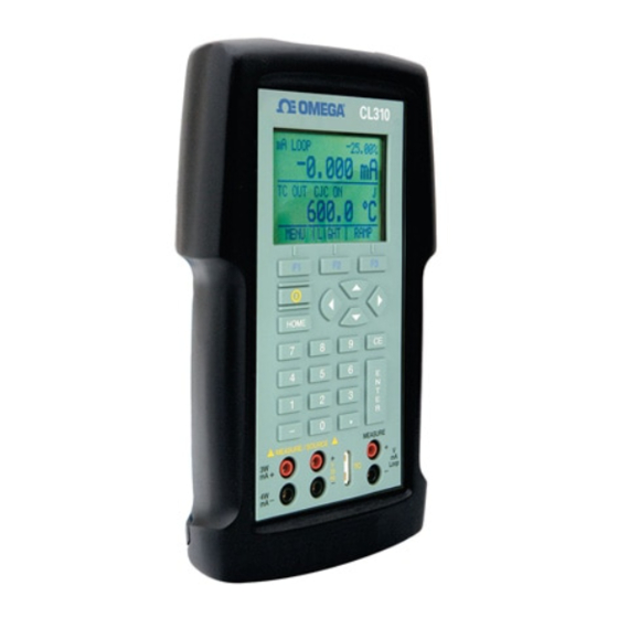
- Page 5 1. Introduction The Omega CL310 Multifunction Process Calibrator is a handheld, battery-operated instrument that measures and sources electrical and physical parameters. The calibrator has the following features and functions: • A dual display. The upper display is used for the measurement of volts, current, and pressure.
- Page 6 Symbol Description AC (Alternating Current) AC-DC Battery CE Complies with European Union Directives Double Insulated Electric Shock Fuse PE Ground Hot Surface (Burn Hazard) Read the User’s Manual (Important Information) The following definitions apply to the terms “Warning” and “Caution”. •...
- Page 7 Warning To avoid possible electric shock or personal injury: • Do not apply more than the rated voltage. See specifications for supported ranges. • Follow all equipment safety procedures. • Never touch the probe to a voltage source when the test leads are plugged into the current terminals.
- Page 8 Caution To avoid possible damage to calibrator or to equipment under test: • Use the proper jacks, function, and range for your measurement or sourcing application. • To avoid mechanically damaging the pressure module, never apply more than 10 ft-lb. of torque between the pressure module fittings, or between the fittings an the body of the module.
-
Page 9: Calibrator Interface
2. Calibrator Interface Figure 1 shows the location of the input and output connections on the calibrator, while Table 1 describes their use. Figure 1. Input/Output Terminals Table 1: Input and Output Terminals Name Description 1, 2 Measure Isolated V, Input terminals for measuring current, voltage, mA terminals and supplying loop power. - Page 10 Figure 2 shows the location of the keys on the calibrator. Table 2 lists the functions of each key. Figure 2. Keypad Table 2. Key Functions Name Function Function Keys Used to operate the menu bar at the bottom of F1, F2, F3 the calibrator display.
-
Page 11: Main Display
2.1 Main Display Figure 3. Display The display of the calibrator, shown in Figure 3, is divided into three main sections: the upper display, the lower display, and the menu bar. The upper display is used for measuring dc voltage, dc current with and without loop power, and pressure. -
Page 12: Menu Bar
Units Shows what unit the measurement or source value is in. Available options are for RTD and TC (°C or °F), and for FREQ and PULSE (CPM, Hz, or KHz) Sensor Types Allow for measurements to be made for different types of RTDs and TCs. - Page 13 [DONE] returns to home menu. Contrast is adjusted using the arrow options, which are available after choosing [CONTRAST]. NOTE: The CL310 calibrator offers a wide range contrast adjustment feature to accommodate operation in extreme temperatures. In certain cases making large changes in contrast may render the display difficult to read under normal conditions.
- Page 14 process to set the contrast back to a default setting. 1. Turn on the unit while holding down the "HOME" key. 2. Hold the key down for a count of 10 seconds to restore contrast default settings. If the display is so dim that you cannot tell if the unit is on or off, use the backlight key to determine if the power is on or off.
- Page 15 8a for instructions. [NEXT] is used to enter the contrast main menu, and [DONE] to return to the home menu. The pressure zeroing main menu is the final variation to choosing [MORE] in the main menu. It has the options [ZERO ], used to zero pressure, [NEXT] and [DONE], which have the same function as above.
- Page 16 Home Menu MENU LIGHT RAMP Selection Menu UPPER LOWER MORE Parameter Selection Document Mode Selection SELECT NEXT DONE DOCUMENT NEXT DONE Home Menu Document Menus Source Mode? Auto Function Menu AUTO FUNC NEXT DONE Frequency Out Frequency Level Menu or Pulse mode? FREQ LEVEL NEXT DONE...
- Page 17 3. Using Measure Modes (Lower Display) 3.1 Measuring volts and frequency Electrical parameters volts and frequency can be measured using the lower display. To make the desired measurements, follow these steps: 1. Switch to the lower display [LOWER] from Main Menu. 2.
- Page 18 be ON and the actual temperature of the thermocouple will be measured. With CJC OFF, the calibrator will measure the difference between the thermocouple at the junction and at its TC input terminal. Note: CJC off mode should only be used when calibration is being done using an external ice bath.
- Page 19 This option can be used along with a table to measure an RTD which is not programmed into the calibrator. 3.4 Measuring Pressure Note: The CL310 is compatible with OMEGA Pressure Modules. The accessory PCL-PMA is required for pressure measurement. Note: Pressure is not read from modules with frequency or pulse train mode enabled.
- Page 20 Caution To avoid mechanically damaging the pressure module, never apply more than 10 ft-lb. of torque between the pressure module fittings, or between the fittings an the body of the module. To avoid damaging the pressure module from overpressure, never apply pressure above the rated maximum printed on the module.
- Page 21 Select [ZERO ]. [SET REFERENCE ABOVE] will appear. Enter the pressure using the keypad. The calibrator stores the Barometric zero offset in non- volatile memory. The zero offset is stored for one absolute pressure module at a time. If a new absolute module is connected this process must be repeated.
- Page 22 Figure 10. Connections for Sourcing Current 4.3-1 HART™ Resistor Selection The CL310 can be set-up so that the 250 ohm resistor required for HART™ configuration devices resides inside the CL310. Enabling the CL310's internal 250 ohm resistor eliminates the need to manually add a series resistor during a HART™...
-
Page 23: Simulating A Transmitter
Enable/Disable Procedure 1. Remove the battery cover and remove the 2 screws that are at the top of the case. 2. Remove the 2 screws on the bottom or lower portion of the case. 3. Gently remove the top half of the case from the bottom. 4. - Page 24 4.5 Sourcing volts To source volts follow these steps: 1. Select lower display from the Main Menu. 2. Choose [VOLTS] from the primary parameters. Switch to input/output control and select output [OUT]. 3. Connect the leads for the voltage source terminals, as shown in Figure 12.
- Page 25 4.7 Sourcing a pulse train The calibrator can produce a pulse train with an adjustable number of pulses at a desired frequency. For example, setting the frequency to 60Hz and the number of pulses to 60 would produce 60 pulses for a period of 1 second.
- Page 26 4. Select the desired thermocouple type from the sensor types. 5. Enter the temperature using the keypad. Figure 14. Connections for Outputting RTDs 4.9 Sourcing Ohms/RTDs To source an RTD, follow these steps: 1. Select lower display from the Main Menu, and choose [RTD] from the primary parameters.
- Page 27 Note: The calibrator simulates a 2-wire RTD. To connect 3- or 4-wire transmitter, use stacking cables, as shown in Figure 15. 4.9-1 Custom RTD A custom curve-fit PRT may be entered into the calibrator for sourcing and measuring. To do so follow these steps: Switch to lower display.
- Page 28 5. Using Isolated Measure Modes (Upper Display) 5.1 Measuring volts and mA Use the following steps to measure the voltage or current output of a transmitter. 1. Select the upper display from the Main Menu. 2. Select the desired primary parameter to be measured. Connect the leads to the isolated inputs of the calibrator, as in Figure 16.
- Page 29 5.2-1 HART™ Resistor Selection The CL310 can be set-up so that the 250 ohm resistor required for HART™ configuration devices resides inside the CL310. Enabling the CL310's internal 250 ohm resistor eliminates the need to manually add a series resistor during a HART™ calibration process.
- Page 30 2. Switch to either upper or lower display from the Main Menu. 3. Select [PRESSURE] from the primary parameters. 4. Select the desired measuring unit. 5. Zero the pressure module. The zero function on the calibrator can be found in the pressure zeroing menu. Figure 18.
- Page 31 Figure 19. Connections for Testing an Output Device 6.2 Calibrating an I/P Device The following steps show how to calibrate a device that controls pressure: 1. Select upper display from the Main Menu, and select pressure from the primary parameters. 2.
- Page 32 transmitter is used in this example. The following steps show how to calibrate a temperature transmitter: 1. From the Main Menu select upper display, and choose current loop [mA LOOP]. 2. Switch to lower display from the Main Menu, and select [TC] from the primary parameters.
-
Page 33: Remote Operation
Figure 22. Calibrating a Pressure Transmitter 7. Remote Operation The calibrator can be remotely controlled using a PC terminal, or by a computer program running the calibrator in an automated system. It uses an RS-232 serial port connection for remote operation. With this connection the user can write programs on the PC, with Windows languages like Visual Basic to operate the calibrator, or use a Windows terminal, such as Hyper Terminal, to enter single... -
Page 34: Changing Between Remote And Local Operation
1. Start Hyper Terminal (located in Accessories/Communications of the Windows Start menu) 2. Select New Connection. 3. For Name enter CL310. Select the serial port that the unit is connected to. 4. Enter the above information for port settings. 5. Select ASCII setup from File/Properties/Settings and mark these... - Page 35 3. To switch back to local operation enter LOCAL at the terminal. This command also turns off LOCKOUT if it was on. For more information on commands refer to the Remote Commands section. 7.3 Using Commands 7.3-1 Command types Refer to the Section on Remote Commands for all available commands.
- Page 36 Overlapped Commands Commands that require more time to execute than normal. The command *WAI can be used after the overlapped command to tell the calibrator to wait until the command finishes before executing the next command. For example: TRIG; *WAI Triggers the pulse train.
- Page 37 Indefinite ASCII (IAD) Any ASCII characters followed by a terminator. For example: *IDN? returns MARTEL, ASC300, 250, 1.00 7.3-4 Calibrator Status Status registers, enable registers, and queues provide status information on the calibrator. Each status register and queue has a summary bit in the Serial Poll Status Byte.
- Page 38 Event Status Register (ESR) A two-byte register, in which the lower bits represent conditions of the Calibrator. Cleared when read and when power is reset. Event Status Enable Register (ESE) Enables and disables bits in the ESR. Setting a bit to 1 enables the corresponding bit in the ESR, and setting it to 0 disables the corresponding bit.
-
Page 39: Remote Commands And Error Codes
Operation Complete. Set to 1 when the calibrator has finished executing all commands before the command *OPC was entered. Error Queue If an error occurs due to invalid input or buffer overflow, its error code is sent to the error queue. The error code can be read from the queue with the command FAULT?. -
Page 40: Table Of Contents
*RST Resets the state of the instrument to the power-up state. This command holds off execution of subsequent commands until it is complete. *SRE Loads a byte into the Service Request Enable register. *SRE? Returns the byte from the Service Request Enable register. *STB? Returns the status byte. - Page 41 Command Description LOCAL Returns user to manual operation of the calibrator LOCKOUT Locks out the keypad of the calibrator, and allows for remote operation only LOWER_MEAS Sets the mode for measuring on the lower display. L_PRES_UNIT Sets the pressure unit on the lower display Sets the output of the calibrator OUT? Returns the output of the calibrator...
- Page 42 Command Description UPPER_MEAS Sets the measuring mode for the upper display. U_PRES_UNIT Sets the upper pressure unit VAL? Returns the measured values ZERO_MEAS Zeros the pressure module ZERO_MEAS? Returns the zero offset of the pressure module Table 7: Parameter units Units Meaning milliamps of current...
-
Page 43: Entering Commands
Error Number Error Description Entry is below the lower limit of the allowable range A required command parameter was missing An invalid pressure unit was received An invalid CJC_STATE was received An invalid TSENS_TYPE was received Pressure module not connected An unknown command was received An invalid RTD or TC parameter value was received The serial input buffer overflowed... - Page 44 *IDN? Returns the manufacturer, model number, and firmware revision of the Calibrator. For example: *IDN? will return OMEGA,CL310,0,2.00 *OPC Enables the Operation Complete setting in the ESR. This setting makes it possible to check if an operations is complete after it has been initialized.
-
Page 45: Cjc_State
*SRE? Returns a byte from the SRE. The byte is returned in decimal format. For example: If 40 is returned, bits 5 and 3 are enabled. *STB Returns the status byte in decimal form from the Serial Poll Status Byte. For example; If 72 is returned, bits 6 and 3 are enabled. -
Page 46: Cprt_Coefa
coefficient of the polynomial used by the custom RTD. For example: CPRT_COEFA 3.908E-03 enters 3.908e-3 as coefficient A. CPRT_COEFA? Returns the number which was entered for the first coefficient of the polynomial used in the custom RTD. Using the example above CPRT_COEFA? Would return: 3.908000E-03 CPRT_COEFB... -
Page 47: Cprt_Min_T
CPRT_MIN_T Sets the minimum temperature of the custom RTD range. The temperature value must be entered with a degrees label, CEL for Celsius and FAR for Fahrenheit. For example: CPRT_MIN_T -260 CEL enters -260°C as the minimum temperature. CPRT_MIN_T? Returns the value entered for minimum temperature in the range for a custom RTD. -
Page 48: Fault
FAULT? Returns the error code number of an error that has occurred. The command may be entered when the previous command did not do what it was meant to do. For example, if a value for current output is entered that is bigger than the supported range (0-24mA) FAULT? Would return: 103 which is the code number for an entry over range. -
Page 49: Freq_Unit
frequency and pulse modes, CPM (cycles per minute), Hz, and kHz. Use this command to select the right range. For example: FREQ_UNIT HZ sets the frequency to Hz range FREQ_UNIT? Returns the frequency unit currently being used by the frequency and pulse modes. -
Page 50: Out
are shown in the Table 7. (Parameter Units). For example: L_PRES_UNIT KPAL sets the pressure unit to kiloPascals Sets the output of the calibrator. This command may be used to output mA, volts, frequency, temperature, and ohms. Frequency output, which is set by the command FREQ_TYPE, is either continuous or pulse. -
Page 51: Remote
REMOTE Puts the calibrator in remote mode. From the remote mode the user can still use the keypad to get back to local unless the command LOCKOUT was entered before REMOTE. Than the keypad is totally locked out, and the user has to send the LOCAL command to get back to local operation. -
Page 52: Sim
Sets the output for current simulation. This command also switches the calibrator into mA simulation mode. A number and a unit must be entered after the command. For example: SIM 5 MA sets the current simulation at 5 mA SIM? Returns the output of the current simulation. -
Page 53: Tc_Type
Second, the status of the tag, a single character 'U' for downloaded uncalibrated or 'C' for calibrated. Third, the tag number string of up to 16 characters. TC_TYPE Sets the type of the thermocouple. All available types are shown in the TC Types table in Section 8. -
Page 54: Tsens_Type
TSENS_TYPE? Returns the type of sensor that is currently set to measure temperature, either TC or RTD. UPPER_MEAS Sets the measuring mode for the upper display. After the command enter DCI for mA, DCI_LOOP for mA with loop power, DCV for volts, and PRESSURE for pressure. - Page 55 8. Document Mode 8.1 Introduction Document mode allows an instrumentation technician to create repeatable calibration tests for up to 50 tags while in the field, to download predefined calibration tests from a PC database for up to 50 tags before going to the field, or some combination of both types up to a maximum of 50 tags.
- Page 56 Once the last point has been tested, the As Found test automatically ends, the real time clock time stamp is saved, and the technician is prompted for changes to the tag identification data (any field but tag number which can not be changed). If test validation was selected, the technician has the option of displaying the As Found test results.
- Page 57 Document Menus Function Selection Menu TEST REVIEW EXIT Home Menu Review Menu Test Selection Menu AS FOUND AS LEFT EXIT Home Menu As Left Menu As Found Tag Selection Menu SELECT EXIT Home Menu Downloaded Tag As Found Test As Found Setup Menu UPPER LOWER DONE...
- Page 58 Frequency Out Pulse/Frequency Level Menu or Pulse Mode? DONE Pulse Mode? Pulse Parameter Menu FREQ COUNTS DONE Upper display is Upper Units Menu manual type? DONE Lower display is Lower Units Menu manual type? DONE Either display in Pressure Zero Menu pressure mode? ZERO DONE...
- Page 59 Pulse mode? AF data collection – pulse trigger TRIGGER READY AF data collection – pulse stop STOP Manual Input or AF data collection – manual entry Output? NEXT DONE ABORT LEFT KEY Manual output entry Manual Output? DONE BACK Manual Manual input entry Input? DONE...
- Page 60 Tag ID field selection SELECT NEXT SAVE Tag field data entry DONE NEXT SAVE Save As Found data and time stamp Validate test results? Tolerance field selection SELECT DONE Tolerance field data entry DONE Show test results? View test results DONE Save AF results as AL? Document Menus...
- Page 61 Downloaded Tag As Found Test Either display in Pressure Zero Menu pressure mode? ZERO DONE Pulse mode? AF data collection – pulse trigger TRIGGER READY AF data collection – pulse stop STOP Manual Input? AF data collection – manual entry NEXT ABORT REPEAT...
- Page 62 Tag ID field selection SELECT NEXT SAVE Tag field data entry DONE NEXT SAVE Save Tag ID data changes Validating Show test results? results? View test results DONE Save AF results as AL? Document Menus Adjust Instrument?
- Page 63 Either display in Pressure Zero Menu pressure mode? ZERO DONE Pulse mode? Adjust – pulse trigger TRIGGER READY Adjust – pulse stop STOP Adjust – monitor/step/enter DOWN AS LEFT As Left Menu As Left tag selection SELECT EXIT Home Menu Already has AL Overwrite AL results? results?
- Page 64 Pulse mode? AL data collection – pulse trigger TRIGGER READY AL data collection – pulse stop STOP Manual Input? AL data collection – manual entry NEXT ABORT REPEAT LEFT KEY Manual input entry DONE BACK AL data collection – save test point Last data point? SAVE ABORT...
- Page 65 Review Menu Review Function Select VIEW PRINT CLEAR View Tag Select SELECT EXIT Print Tag Select SELECT EXIT View Tag DONE EXIT Review Menu Clear Tag Select SELECT CLEAR ALL EXIT Confirm Tag Clear Confirm Clear All Tags Review Menu Final Confirm Clear All Tags...
- Page 66 Function Selection Menu TEST REVIEW EXIT Review Function Select VIEW PRINT CLEAR Test Selection Menu AS FOUND AS LEFT EXIT Select Tag for Testing Download Tag Source? Configure Upper and Select Tag for Testing Lower Displays Collect As Left Test Data Collect As Found Test Collect As Found Test Data...
- Page 67 8.2 New Tag As Found Test 8.2.1 Setup At the main menu, press the MENU function key, followed by the MORE function key, followed by the DOCUMENT function key to display the first level document mode menu. Press the TEST function key to display the test selection menu. Press the AS FOUND function key to display the As Found Tag Selection menu which shows all uncalibrated downloaded tags.
- Page 68 These two menus operate the same as the normal upper and lower type and parameter selection menus described earlier in this manual, except that they have two extra type selections, MANUAL IN and MANUAL OUT. The currently selected parameter field blinks (indicated by bold italicized text above).
- Page 69 Up to 5 characters may be entered for a unit description using a telephone style entry method. The four lower lines provide a mapping of the allowed alphanumeric characters to the numeric keypad keys. To enter a character press the corresponding numeric key multiple times to cycle through the mapped characters until the desired character is displayed.
- Page 70 The value displayed on the top line is the current pressure reading adjusted with the current reference pressure. Enter the new reference pressure using the numeric keys followed by the ENTER key, or if satisfied with the current reference value press the DONE function key to bypass changing it.
- Page 71 Enter the new peak to peak voltage using the numeric keys followed by the ENTER key, or if satisfied with the current voltage press the DONE function key to bypass changing it. When satisfied with the voltage value, press the DONE function key to continue. Pulse train has two variable parameters, frequency and pulse count.
- Page 72 8.2.2 Data Collection The test for each point consists of setting the output value, waiting for the input to settle, and saving the data. This process is repeated until the desired number of test points are recorded. For ease of analysis, it is suggested that the test points be evenly spaced across the test range and that they be entered in ascending order, descending order, ascending followed by descending, or...
- Page 73 saving any data, press either the HOME key or the ABORT function key. A prompt is displayed requesting confirmation that the test data accumulated so far is to be abandoned. Press the NO function key to return to the data collection process at the point where it was interrupted.
- Page 74 the following paragraphs for a description of the DONE and ABORT function keys. If the calibrator is not manual, or after manual data has been entered, the lower line changes to the following prompts. If the data displayed is correct, press the SAVE function key to save the data and step to the next point.
- Page 75 the desired test value. For all other output types, enter the output value to be generated using the numeric keys, followed by ENTER. If the calibrator input is not manual, wait for the displayed calibrator input value to settle and then press the NEXT function key to prompt for the manual entry(s) as described in the following subsection.
- Page 76 8.2.3 Identification Data Entry When the DONE function key is pressed at the data collection stage, the first page of the following two page identification data display is shown. Initially all data fields are blank, but after data is entered the current value of each field is shown to the right of its description.
- Page 77 Up to 16 characters may be entered for the field using a telephone style entry method. The four lower lines provide a mapping of the allowed alphanumeric characters to the numeric keypad keys. To enter a character press the corresponding numeric key multiple times to cycle through the mapped characters until the desired character is displayed.
- Page 78 If the instrument's output/input relationship is not linear, test results validation should not be selected. Press the YES function key to validate the results. Press the NO function key to bypass validation and proceed to the test conclusion stage. When validation is selected, the following prompt is displayed showing the current settings for output zero and span, input zero and span, and the % span error tolerance.
- Page 79 The overall test status display provides the option of displaying details for each test point. The overall test status is displayed on the top line. If all points passed, PASSED is displayed. If one or more points have failed, FAILED is displayed. Press the NO function key to bypass detail results display and proceed to the test conclusion stage.
- Page 80 If pressure is selected on the upper or lower display, the pressure zero prompt is displayed first and operates as described under As Found Setup. The prompt displayed during the test depends on the input and output types selected. Any combination which includes pulse train output has its own unique prompt sequence.
- Page 81 The PT in the upper right corner of the display indicates that this is the adjustment display. If an As Found data point is selected, its number is displayed. If a user entered value is selected, two dashes are displayed. Use the numeric keys, followed by ENTER, to enter a user value for generation, or press the READY function key to proceed to the next menu where the UP and DOWN function keys can be used to scroll...
- Page 82 8.4 Downloaded Tag As Found Test 8.4.1 Tag Selection At the main menu, press the MENU function key, followed by the MORE function key, followed by the DOCUMENT function key to display the first level document mode menu. Press the TEST function key to display the test selection menu. Press the AS FOUND function key to display the As Found Tag Selection menu which shows all uncalibrated downloaded tags.
- Page 83 1) The test outputs can not be changed, they will be the predefined values that were downloaded. For pressure and manual output types, the downloaded value is displayed for the technician to set it on the external source. For all other output types, the calibrator automatically generates the As Found value.
- Page 84 Press the TEST function key to display the test selection menu. Press the AS LEFT function key to display the tag selection prompt which shows all previously calibrated tags available for recalibration. Tag numbers are displayed on multiple pages, six tags to a page. Press the UP ARROW and DOWN ARROW keys to scroll the tag selector highlight one tag at a time, scrolling from page to page, cycling from top to bottom of the list and vice versa.
- Page 85 1) The AF in the upper right corner of the display is changed to AL to indicate that this is an As Left test. 2) The test outputs can not be changed, they will be the same as the As Found values. This ensures that the As Found and As Left test results line up when being compared later.
- Page 86 The letter U indicates an uncalibrated downloaded tag, the remainder have been calibrated. Tag numbers are displayed on multiple pages, six tags to a page. Press the UP ARROW and DOWN ARROW keys to scroll the tag selector highlight one tag at a time, scrolling from page to page, cycling from top to bottom of the list and vice versa.
- Page 87 Connect a serial interface printer to the serial port of the CL310, turn the power on and ensure that it is warmed up and ready to print.
-
Page 88: Setting The Date And Time
8.8 Clearing Test Results At the main menu, press the MENU function key, followed by the MORE function key, followed by the DOCUMENT function key to display the first level document mode menu. Press the REVIEW function key to display the review selection menu. Press the CLEAR function key to display the tag selection prompt and clear menu options. -
Page 89: System Requirements
Press the HOME key to exit the data entry screen without changing the clock. 9. CL310-SW Utility Program The CL310-SW (Upload, Save, View) Utility program is a Microsoft Windows based application which aids in the download of tag test configurations and the retrieval of test results from the CL310 calibrator, and organizing its storage on your PC. - Page 90 Choose the menu option "Install Omega CL310-SW Utility Software." Follow the on-screen prompts to complete the installation. As an alternative, use Explorer to browse to the "\Omega CL310-SW" directory on the CD and run SETUP .EXE. Follow the on-screen prompts to install the application.
-
Page 91: File Menu
The Help menu contains the application help, support, and program information. 9.4 File Menu Initially CL310-SW is set to store reports in the root folder 'Omega CL310-SW' within the 'My Documents' folder. If you wish to store them into another folder, navigate to the alternate folder before saving the first report. - Page 92 directory, the file is saved there. If the tag subdirectory does not exist within the root directory, the tag subdirectory is created and the file is saved there. If the reports were uploaded from a calibrator, the file extension is TXT or CSV depending on the report format selection on the Upload menu at the time the reports were uploaded.
- Page 93 Selected Tag Reports Upload selected tag calibration reports from the calibrator into the Reports list box. Before using this function, upload a list of the tag configurations contained in the calibrator using the Tag ID's function above. In the Tag ID's list box, highlight the tags which are to be uploaded, and then select this function to upload them.
- Page 94 9.6 Erase Menu All Tags Erase all tag configurations from the calibrator. Both list boxes are cleared after the erasure. Use the Configure menu to select the communications port. Selected Tags Erase selected tag configurations from the calibrator. Before using this function, upload a list of the tag configurations contained in the calibrator into the Tag ID's list box using the Tag ID's function on the Upload menu.
- Page 95 Click the OK button to dismiss 9.8 Configure Menu Initially CL310-SW is set to store tags and groups in the root folder 'Omega CL310-SW' within the 'My Documents' folder. If you wish to store them into another folder, navigate to the alternate folder before saving the first tag or group.
- Page 96 Display a tag configuration, and optionally print it. Group Initially CL310-SW is set to store tags and groups in the root folder 'Omega CL310-SW' within the 'My Documents' folder. If you wish to store them into another folder, navigate to the alternate folder before saving the first tag or group.
- Page 97 COM Port The communications port is selected by clicking on one of the following menu items. The selected port is indicated by the menu item with the checkmark, and is also displayed on the status line at the bottom of the screen. Use COM1 Use COM2 Use COM3...
- Page 98 The CJ field appears only for the Thermocouple type. It contains a drop down list presenting all of the available options for a standard calibrator. Select the cold junction option corresponding to the instrument to be calibrated. If your calibrator contains special software implementing a non?standard cold junction option, enter the text string for it as documented in the user manual addendum accompanying your calibrator.
- Page 99 The Wires field appears only for the RTD type. It contains a drop down list presenting all of the available options for a standard calibrator. Select the connection option corresponding to the instrument to be calibrated. If your calibrator contains special software implementing a non?standard connection option, enter the text string for it as documented in the user manual addendum accompanying your calibrator.
- Page 100 of the group must reside in the same directory as the group. To add tags to the group, highlight them in the available list and click the right arrow. To add a single tag, double click it. To remove tags from the group, highlight them in the group list and click the left arrow.
-
Page 101: Specifications
10. Specifications All measurements apply at 23°C ± 5°C. unless specified otherwise. Outside of this range the stability of the measurements is ± 0.005%of reading/°C. Table 9: General Specifications Operating Temperature -10°C to 50° Storage Temperature -20°C to 70°C Power 4 X AA batteries;... - Page 102 Table 12: Frequency Measurement/Source Range Accuracy (% of reading ± floor) Read 2.0CPM - 600.0CPM 0.05% ± 0.1CPM 1.0Hz - 1000.0Hz 0.05% ± 0.1Hz 1.00KHz - 10.00KHz 0.05% ± 0.01KHz Source 2.0CPM - 600.0CPM 0.05% 1.0Hz - 1000.0Hz 0.05% 1.00KHz - 10.00KHz 0.125% Input voltage amplitude range on frequency is 1V to 20V zero based square wave only.Output amplitude is adjustable from 1V to 20V, and is a square wave with 50% duty...
- Page 103 Table 16: Thermocouple Read and Source (errors in °C) TC Type Range (°C) Accuracy -210.0 - 0.0 0.0 - 800.0 800.0 - 1200.0 -200.0 - 0.0 0.0 - 1000.0 1000.0 - 1372.0 -250.0 - 0.0 0.0 - 400.0 -250.0 - -100.0 -100.0 - 1000.0 0.0 - 1767.0 0.0 - 1767.0...
- Page 104 RTD Type Range (°C) Uncertainty Miniumum Maximum 1 year (°C) PT385, 50 ohm -200 0.18 0.25 0.21 0.26 0.29 0.34 0.39 PT385, 100 ohm -200 0.10 0.13 0.18 0.20 0.25 0.29 PT3926, 100 ohm -200 0.10 0.11 0.13 0.17 0.19 0.24 PT3916, 100 ohm -200...
- Page 105 RTD Type Range (°C) Uncertainty Miniumum Maximum 1 year (°C) PT385, 1000 ohm -200 0.10 0.12 0.14 0.17 0.18 0.19 0.25 NI120 0.06 Cu10 -100 0.82 Cu50 -180 0.20 Cu100 -180 0.13 YSI 400 0.05 Read Accuracy is based on 4-wire input. For 3-wire input add ± 0.05 assuming all three RTD leads are matched.
- Page 106 11.1 Replacing Batteries Replace batteries as soon as the battery indicator turns on to avoid false measurements. If the batteries discharge too deeply the CL310 will automatically shut down to avoid battery leakage. Note: Use only AA size alkaline batteries or optional rechargeable battery pack.
- Page 108 Service Department will issue an Authorized Return (AR) number immediately upon phone or writ- ten request. Upon examination by OMEGA, if the unit is found to be defective, it will be repaired or replaced at no charge. OMEGA’s WARRANTY does not apply to defects resulting from any...
- Page 109 Where Do I Find Everything I Need for Process Measurement and Control? OMEGA…Of Course! Shop online at www.omega.com TEMPERATURE Thermocouple, RTD & Thermistor Probes, Connectors, Panels & Assemblies Wire: Thermocouple, RTD & Thermistor Calibrators & Ice Point References Recorders, Controllers & Process Monitors...