
Related Manuals for Omega PCL1000


Summary of Contents for Omega PCL1000
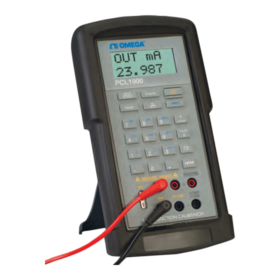
- Page 1 User’s Guide Shop online at omega.co e-mail: info@omega.com For latest product manuals: www.omegamanual.info NORWALK, CT PCL1000 Multi-Function Calibrator...
- Page 2 Fax: (203) 359-7700 e-mail: info@omega.com For Other Locations Visit omega.com/worldwide The information contained in this document is believed to be correct, but OMEGA accepts no liability for any errors it contains, and reserves the right to alter specifications without notice.
-
Page 3: Table Of Contents
Table of Contents 1. Introduction 2. Quick Start Instructions A. Key Functions ........4 B. -
Page 5: Introduction
PCL1000 1. Introduction The PCL1000 is designed to be a versatile, easy to use multi-function cali- brator with a simple user interface. The following instructions will allow the user to begin simple calibration tasks by learning the basic operation of the keys and their functions. - Page 6 Symbol Description AC (Alternating Current) AC-DC Battery CE Complies with European Union Directives Double Insulated Electric Shock Fuse PE Ground Hot Surface (Burn Hazard) Read the User’s Manual (Important Information) The following definitions apply to the terms “Warning” and “Caution”. •...
- Page 7 Warning To avoid possible electric shock or personal injury: • Do not apply more than the rated voltage. See specifications for supported ranges. • Follow all equipment safety procedures. • Do not use the calibrator if it is damaged. Before you use the calibrator, inspect the case.
-
Page 8: Quick Start Instructions
2. Quick Start Instructions A. Key Functions Function Input/Output Toggles the function selected from measurement mode to source mode. V/mA/Hz Selects between volts, milliamps, and frequency modes TC/RTD Selects between temperature modes either T/C or RTD. Ohms and mV ranges are also included in these functions. Ranges/Units This key toggles through all the ranges for a chosen func- tion. - Page 9 3. Automated Stepping The PCL1000 can auto-step through some or all of the stored set- points for a given range. The procedure is as follows: a. Press “Shift” followed by auto. b. “Auto SPT ?” will appear. Enter the ending setpoint location.
-
Page 10: Connection Diagrams & Instructions
3. Connection Diagrams & Instructions A. Measuring High Voltage AC or DC 1. Select the Voltage Input Mode. Use the “Range” key to select either AC or DC input. 2. Connect the device to be measured as shown in Figure 1. ! WARNING ! When measuring high voltage be sure to use proper connections as shown in Figure 1. -
Page 11: Measuring Current
Figure 2. ! WARNING ! Do not exceed 20 VDC at the V/Ω/Hz input. C. Measuring Current 1. Select the mA input mode. Note: To power the loop while reading cur- rent, select the “mAPW” mode. 2. Connect the device under test as shown in Figure 3. 3. -
Page 12: Simulating Current
3. In the resistance or frequency modes use the “Range” key to choose the desired range for the mode you’re operating in. 4. The PCL1000 is capable of driving up to ±1 mA on the Voltage and Frequency ranges and is able to handle up to a 3 mA excitation on the Resistance Simulation Range. -
Page 13: Sourcing A Thermocouple Signal
RTD mode. Then use the “Range” key to select the desired range within the RTD mode. 2. Make sure the PCL1000 is in the Input Mode (Note: that it will indicate 2, 3, or 4W in the upper left corner of the LCD). -
Page 14: Sourcing Resistance (Rtds)
Figure 9. J. Sourcing Resistance Into a RTD Transmitter 1. As described previously in section F the PCL1000 can source resistance in a RTD Transmitter or measuring device. In many cases the unit under test will require a 3 or 4 wire connection to achieve best accuracy. Refer... -
Page 15: Maintenance
Figure 10. 4. Maintenance A. Power Requirements The PCL1000 operates on 4 AA alkaline batteries. To replace the alkaline bat- teries, remove the two (2) screws on the rear battery door and lift the battery cover. B. Calibration The PCL1000 should hold its rated specifications for a minimum of one... -
Page 16: Specifications
5. Specifications Pressure Module Dependent Operates with selected PX971 Ranges: Transducers T/C Ranges: J, K, T, E, R, S, N, B, L, U including – 10 to 70mV RTD Ranges: Pt 385 (100, 200, 500, 1000 ohms) Pt 392, JIS, Ni120, CU10, YSI400 Ohms Ranges: 0 to 400.00 and 400.0 to 4000.0 mA Range:... - Page 17 Range & Accuracy (cont.) Range Accuracy (% of reading ± counts) Ohms Read (low) 0.00 400.00 0.1 ohm Ohms Read (high) 400.0 1500.0 0.5 ohm 1500.1 3200.0 1.0 ohm Range Excitation Accuracy Current Ohms Source (low) 5.00 400.00 0.1 to 0.5 mA 0.15 ohm 5.00 400.00...
- Page 19 Department will issue an Authorized Return (AR) number immediately upon phone or written request. Upon examination by OMEGA, if the unit is found to be defective, it will be repaired or replaced at no charge. OMEGA’s WARRANTY does not apply to defects resulting from any action of the purchaser, including but not limited to mishandling, improper interfacing, operation outside of design limits, improper repair, or unauthorized modification.
- Page 20 Where Do I Find Everything I Need for Process Measurement and Control? OMEGA…Of Course! Shop online at omega.com TEMPERATURE Thermocouple, RTD & Thermistor Probes, Connectors, Panels & Assemblies Wire: Thermocouple, RTD & Thermistor Calibrators & Ice Point References Recorders, Controllers & Process Monitors...