
Related Manuals for Kenwood Nexedge


Summary of Contents for Kenwood Nexedge
-
Page 1: Instruction Manual
NX-410 800MHz DIGITAL TRANSCEIVER INSTRUCTION MANUAL ÉMETTEUR-RÉCEPTEUR NUMÉRIQUE 800MHz MODE D’EMPLOI TRANSCEPTOR DIGITAL 800MHz MANUAL DE INSTRUCCIONES © B62-XXXX-00 (K) 09 08 07 06 05 04 03 02 01 00... - Page 2 800MHz DIGITAL TRANSCEIVER NX-410 INSTRUCTION MANUAL Terminal Descriptions Universal connector It is possible to use a resin-based cover for the Universal connector. Name Description Impedance Ext/Int Speaker Switch Input High Impedance BTL Output + for External Speaker BTL Output - for External Speaker Ext/Int MIC Switch Input High Impedance External MIC Input...
- Page 3 We are grateful you have chosen Kenwood for your land mobile radio applications. This instruction manual covers only the basic operations of your NEXEDGE portable radio. Ask your dealer for information on any customized features they may have added to your radio. NXDN™...
- Page 4 One or more of the following statements may be applicable: FCC WARNING This equipment generates or uses radio frequency energy. INFORMATION TO THE DIGITAL DEVICE USER REQUIRED BY THE FCC user is encouraged to try to correct the interference by one or more of...
- Page 5 Kenwood Kenwood Kenwood Kenwood Kenwood Kenwood Kenwood Kenwood Kenwood...
- Page 6 RECAUTIONS Kenwood. touch the damaged parts. accessories.
- Page 7 Turn the transceiver power off in the following locations: Turn the transceiver power off in the following locations, unless the model is specifically qualified for such use (Intrinsically Safe such as approved by Factory Mutual, CSA):...
- Page 8 Kenwood in your area. conditions.
- Page 9 NFORMATION CONCERNING THE BATTERY PACK • Do not disassemble or reconstruct battery! • Do not short-circuit the battery! objects to heat up. • Do not incinerate or apply heat to the battery! • Do not use or leave the battery near fires, stoves, or other heat generators (areas reaching over 80°C/ 176°F)! •...
- Page 10 • Do not charge the battery near fires or under direct sunlight! • Use only the specified charger and observe charging requirements! • Do not pierce the battery with any object, strike it with an instrument, or step on it! •...
- Page 11 • Do not reverse-charge or reverse-connect the battery! • Do not touch a ruptured and leaking battery! • Do not charge the battery for longer than the specified time! • Do not place the battery pack into a microwave or high pressure container! •...
- Page 12 CONTENTS ....................1 UPPLIED CCESSORIES ....................2 NSTALLING EMOVING THE PTIONAL ATTERY ..........2 NSTALLING THE PTIONAL NTENNA ............3 NSTALLING THE ....3 NSTALLING THE AP OVER THE NIVERSAL ONNECTOR ..3 NSTALLING THE PTIONAL PEAKER ICROPHONE OR EADSET .............4 ..................6 ISPLAY ........................9 ON/ OFF ............9 WITCHING...
- Page 13 ............DTMF (D ......20 ULTI REQUENCY ALLS ) ............21 RUNKING ALLS NALOG ..............22 MERGENCY ALLS ................22 CRAMBLER ................23 IGNALING (VOX) ........24 OICE PERATED RANSMISSION ............................26 LOCK .................26 IBRATOR (TOT) .............26 IMER ................27 ATTERY AVER ................27 .............27 ATTERY ARNING ............27 IGNAL TRENGTH NDICATOR...
-
Page 14: Belt Clip
Note: These unpacking instructions are for use by your Kenwood dealer, an authorized Kenwood service facility, or the factory. Carefully unpack the transceiver. We recommend that you identify the items listed in the following list before discarding a claim with the carrier immediately. -
Page 15: Attery P Ack
1 Match the guides of the battery pack with the grooves on the upper rear of the the battery pack in place. 2 Lock the safety catch to prevent accidentally releasing the battery pack. 3 To remove the battery pack, lift the safety catch, press the release latch, then pull the battery pack away from the... -
Page 16: U Niversal C Onnector
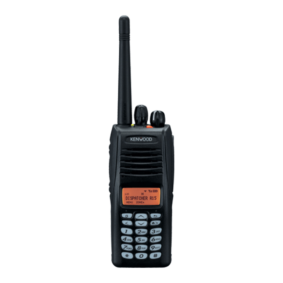
Belt clip Attach the belt clip using the supplied 3 x 8 mm screws. Note: If the belt clip is not installed, its mounting location may get hot during continuous transmission or when left sitting in a hot environment. 3 x 8 mm screws Do not use glue which is designed to prevent screw loosening when installing the belt clip. - Page 17 ① Selector knob Rotate to select a zone or channel/group ID (default). ② Power switch/ Volume control Rotate to turn the transceiver ON/OFF and to adjust the volume. ③ Transmit/ Receive/ Battery low indicator If enabled by your dealer, lights red while transmitting, green while receiving a call (Conventional channels only), and orange when receiving an optional signaling call (DTMF signaling, etc.).
- Page 18 ⑤ Side 1 key Press to activate its programmable function {page 7}. The default is Squelch Off Momentary. ⑥ PTT (Push-To-Talk) switch Press and hold this switch, then speak into the microphone to call a station. ⑦ Side 2 key Press to activate its programmable function {page 7}.
-
Page 19: D Isplay
Indicator Description Monitor or Squelch Off is activated. Blinks when an incoming call matches your Optional Signaling. The current zone (left icon) or CH/GID (right icon) is added to scan. Scan is in progress. Blinks while scan is paused. A message is stored in memory. Blinks when a new message has arrived. - Page 20 Following is a list of available programmable functions. Please contact your dealer for further details on those functions which have been programmed on your transceiver. • Lone Worker • Auto Reply Message • Auto Telephone • Low Transmit Power • Maintenance •...
- Page 21 • Voice Memo • Zone Down • • Zone Up • Zone Delete/Add Available only for Analog Conventional operation. Available only if the VGS-1 optional board has been installed. Available only for Analog Trunking operation. Available only for Analog Conventional, Analog Trunking, and NXDN Conventional operation.
-
Page 22: Volume
Turn the Power switch/ Volume control clockwise to switch the transceiver ON. Turn the Power switch/ Volume control counterclockwise fully to switch the transceiver OFF. If the transceiver is password protected, “PASSWORD” will appear on the display when the power is turned ON. To unlock the transceiver, enter the password: 1 Select a character using the DTMF keypad. -
Page 23: Group Id
Select the desired zone using (default). Each zone contains a group of channels. Select the desired channel/group ID using the Selector knob (default). Each channel/group ID is programmed with settings for transmitting and receiving. • You can toggle the display between the zone and channel/group ID names and number by pressing the key programmed as Display Format, or by accessing the Menu {page 12}. - Page 24 If a key has been programmed with Individual or Individual + Status persons. 1 Press the key programmed as Individual or Individual + Status. 2 Press to select a unit ID from the list. • You can enter the unit ID directly, using the DMF keypad. 3 Press and hold the PTT switch to make the call.
-
Page 25: On/Off
through the Menu instead of physical controls. Once you become familiar with the Menu system, you will appreciate the versatility it offers. 1 Press the key programmed as Menu. • The category list is shown. • When there is only 1 category, the function list is shown (proceed to step 4). - Page 26 Display Description BROADCAST Broadcast ON/OFF CLOCK Clock ON/OFF CLOCK ADJUST Clock Adjustment mode DIRECT CH1 SEL Direct CH/GID 1 ~ 5 Select DISP FORMAT Display Format ON/OFF FIXED VOLUME Fixed Volume FORCED SEARCH Forced Search GPS POS DISP GPS Position Display mode GROUP Group mode GROUP+STATUS...
- Page 27 Display Description SQUELCH OFF Squelch Off ON/OFF STACK Stack mode STATUS Status mode SHORT MESSAGE Short Mesage mode TALK AROUND Talk Around ON/OFF PASSWORD Transceiver Password mode VIBRATOR Vibrator ON/OFF VOICE MEMO Voice Memo mode VOX LEVEL VOX Level mode VOX ON/OFF ZONE DEL/ADD Zone Delete/A dd...
- Page 28 Scan monitors for signals on the transceiver channels. While scanning, the transceiver checks for a signal on each channel and only stops if a signal is present. To begin scanning, press the key programmed as Scan. • icon appears on the display. •...
- Page 29 The Scan Revert channel is the channel selected when you press the PTT switch to transmit during scan. Your dealer can program one of the following types of Scan Revert channels: • Selected: The last channel selected before scan. • Selected + Talkback: Same as “Selected”, plus you can respond to calls on the channel at which scan is paused.
- Page 30 FleetSync is an Alphanumeric 2-way Paging Function, and is a protocol owned by Kenwood Corporation. Note: This function is available only in analog operation. A Selcall is a voice call to a station or group of stations. 1 Select your desired zone and channel.
- Page 31 • Select “ALL” Fleet and “ALL” ID to make a call to all units (Broadcast call). You can send and receive 2-digit Status messages which may be decided in your talk group. Messages can contain up to 16 alphanumeric characters. Status messages range from 10 to 99 (80 ~ 99 are reserved for special messages).
-
Page 32: Essages
appear when a Status call is received. Press any key to return to normal operation. 1 Press the key programmed as Stack, or press and hold the key programmed as Selcall, Status, or Selcall + Status to enter Stack mode. •... -
Page 33: Call
Manual Dialing 1 Press and hold the PTT switch. 2 Enter the desired digits using the DTMF keypad. • If you release the PTT switch, transmit mode will end even if the complete number has not been sent. • If the Keypad Auto PTT function has been enabled by your dealer, you do not need to press the PTT swich to transmit;... - Page 34 This function is used when a transceiver is stolen or lost. When the transceiver receives a call containing a stun code, the transceiver becomes disabled. The stun code is cancelled when the transceiver receives a call with a revive code. Manual Dialing 1 Select your desired zone and telephone group ID.
-
Page 35: S Crambler
If your transceiver has been programmed with the Emergency function, you can make emergency calls. 1 Press and hold the key programmed as Emergency. • Ask your dealer for the length of time necessary to hold this key before the transceiver enters Emergency mode. •... -
Page 36: S Ignaling
Your dealer may have programmed QT or DQT signaling on your transceiver channels. A QT tone/ DQT code is a sub-audible tone/code which allows you to ignore (not hear) calls from other parties who are using the same channel. Operator Selectable Tone (OST) If a key has been programmed with OST, you can reprogram the QT/DQT settings on each of your channels. - Page 37 Your dealer may also program several types of optional signaling for your transceiver channels. DTMF Signaling: DTMF Signaling opens the squelch only when the transceiver receives a call containing a matching DTMF code. FleetSync Signaling: Refer to “S ELCALL ELECTIVE )”...
- Page 38 1 Connect the headset to the transceiver. 2 Press and hold the key programmed as VOX for 2 seconds. 3 To transmit, simply speak into the microphone. • The transceiver recognizes sound levels depending on the VOX Gain level. If it is too sensitive, it will transmit when there is noise in the background.
-
Page 39: Clock
Your dealer can activate a variety of transceiver functions to perform without any additional operation on your part. If activated by your dealer, you can view the clock by pressing the key programmed as Clock. Note: Removing or leaving the battery pack uncharged for extended periods will clear the clock time. -
Page 40: Key Lock
The Battery Saver can be activated only on Conventional channels. This function decreases the amount of power used when a signal is not being received and no operations are being performed. Press the key programmed as Key Lock to lock and unlock the transceiver keys. - Page 41 If programmed by your dealer for a channel, the compander will remove excessive noise from transmitted signals, to provide higher clarity of signals. Note: The COMPANDER is used only in analog operation. On Conventional channels, if BCL is set up by your dealer, you will be unable to transmit if the channel is already in use.
-
Page 42: V Oice R Ecorder
The voice recorder allows you to record conversations and create voice memos. If activated, the auto recorder will continuously record all transmitted and received signals. The recording storage area retains only the last 30 seconds of recording. To record a voice memo for later playback: 1 Press the key programmed as Voice Memo, press and hold the key programmed as Playback, or access the Menu {page 12}. - Page 43 • If there is memory available on your transceiver, “I am not available. Leave your Message.” will be sent to the caller and they can leave you a recorded message. When a message is stored on your transceiver, “NEW MESSAGE” appears on the display.
- Page 45 Use only Kenwood authorized accessories (antennas, battery packs, belt clips, Speaker/ Mics or headsets etc.): When worn on the body, always place the radio in a Kenwood recommended clip or carrying case meant for this product. The use of other than recommended or approved body- worn accessories may result in RF exposure levels which exceed the FCC’s occupational/ controlled...